Table of Contents
Advertisement
Quick Links
Advertisement
Table of Contents

Summary of Contents for MIP LM 3188
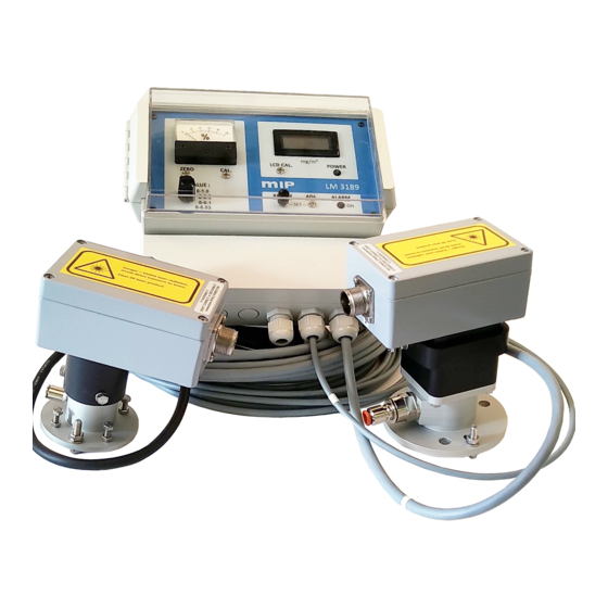
- Page 1 22.05.2013 MIP LASER DUST MONITOR LM 3188 USER’S MANUAL Marked for following units. Monitor Unit 3188799 Transmitter Unit: L956(LM) Receiver Unit: R815(LM) 0…1.0D ( mg /m Range: Options: - Universal power Please note that Monitor unit test cards are end of manual.
-
Page 2: Table Of Contents
APPLICATIONS FOR DIFFERENT LASER MODELS ............ 6 THEORY OF OPERATION ....................6 OPACITY DEFINITION ..................... 7 D-VALUE DEFINITION ....................7 MASS-VALUE DEFINITION .................... 7 INTRODUCTION OF LASER DUST MONITOR LM 3188 ..........9 CONTROLS, DISPLAYS AND SETTINGS ..............10 3.1.1 Indicating meter [1] ....................10 3.1.2 Range selector [2] .................... - Page 3 APPENDIX 9: LASER UNIT L 318 PCB-LAYOUT ..............32 APPENDIX 10: RECEIVER UNIT R 318 PCB-LAYOUT ............33 APPENDIX 11: LM 3188 WIRING ....................34 APPENDIX 12: LM 3188 WIRING; UNIVERSAL POWER OPTION ........35 APPENDIX 13: INSTALLATION EXAMPLES ................37 APPENDIX 14 : INSTALLATION ....................39 APPENDIX 15: MATING FLANGE EXAMPLES ...............
-
Page 4: Introduction
Page 4 (41) INTRODUCTION ADVANTAGES AND FEATURES During the recent years the mass production of different types of lasers has made them eco- nomically viable products for a broad range of applications, dust monitors among others. There are two main families of lasers: ... -
Page 5: Different Laser Models
Gas laser LM 3086, Semiconductor model LM 3188 and Superled model LX 3188. The basic models are LM 3086 and LM 3188. Both models function with the same principle measuring directly laser light extinction as optical density. Here is how they differ from each... -
Page 6: Applications For Different Laser Models
LM 3188 where the space is limited. LX 3188 Superled model can be used instead of LM 3188 where the measuring length is short enough (<2m) or where the price is of primary importance. THEORY OF OPERATION When a monochromatic light beam, such as laser beam, traverses through gas that contains particulate matter, the intensity of the beam will decrease by absorption and scattering pro- cesses within the particle distribution. -
Page 7: Opacity Definition
To account for many different applications and measurement set-ups the D-value as solved from the eq. (3), is the basic quantity for the MIP-monitors. Thus the indicator range is scaled in D-values and optical filters with known D-values are readily available to check the proper operation of the instrument. - Page 8 Page 8 (41) micrometers Where d = particle diameter = particle density grams/cm 3 meters L = measurement length in dust optical density D = measured D-value grams/m 3 M = mass concentration of dust This “mass formula”...
-
Page 9: Introduction Of Laser Dust Monitor Lm 3188
It has large operation range (0 … 90 %). Its optic need is minimum so there is less maintenance. LM 3188 has good stability and reliability. LM 3188 has both analogue and digital display in monitor unit. There are 4 operator selectable measuring ranges. Most of controls and displays are included in monitor unit. -
Page 10: Controls, Displays And Settings
Page 10 (41) CONTROLS, DISPLAYS AND SETTINGS The faceplate of the M 318 monitor unit is pictured which is below. Controls displays and settings are indicated by numbers 3.1.1 Indicating meter [1] Indicating meter, which displays the %-value in selected D-range. If, for instance, the reading is 40 % and the selected D-range is 0…0,3 D, then the measured D-value is 0,3 D ... -
Page 11: Zero Set Screw [3]
Page 11 (41) 3.1.3 Zero set screw [3] This is very important adjustment, which allows after installation to set zero (D-value) level. The zeroing should happen in as dustless condition as possible. When measuring path is clear of any interfering particles, the zero screw is turned until the meter (and display) indi- cates 0-reading. -
Page 12: Installation And Calibration
Page 12 (41) INSTALLATION AND CALIBRATION 4.1. INSTALLATION It is clear, that the installation environment is different in each application. That is why we pro- vide only a minimum of installation hardware with the instrument. The gas laser has a specific installation foot and semiconductor lasers as well as all receivers, come with the flanges that have elliptic holes for adjustment. - Page 13 Page 13 (41) 3: Use 10mm wrench to adjust position of the reveiver unit. (Version with upgraded purge air flow pictured). Main alignment adjustment should be done from transmitters installationg flange as shown on pictures 1 and 2. As the laser beam is very compact, only small holes (10…50 mm dia) to get beam through, are needed.
- Page 14 Factors 1 and 2 relates to measuring angle and inherent intensity fluctuation in both LM 3086 and LM 3188, as discussed in connection with mass density estimation. The mass formula can be used to estimate the mass concentration range, based on particle properties and path...
-
Page 15: Calibration
Page 15 (41) Factor 3 refers to allowed beam direction changes that can point the beam outside the detec- tor. The beam profile differs in He-Ne and semiconductor lasers. In the He-Ne laser, the criti- cal distance, where beam diameter exceeds the receiver active area, is around 13…18 m. For the semiconductor model this is 25…35m. -
Page 16: Filter Set For The Dust Monitors Instructions For The Use
R 318 surface. If this is no possible, then as near the receiver as possible. The indication of the LM 3188 should now increase to D+X, where X is the filter’s D-value giv- en in associated filter graphs, at the wavelength 655 nm. Use the filter consistent with the measurement range, ie. - Page 17 Page 17 (41) Next, use the same filter and the range 0…3,0 D and the result should now be: %-indication = 0,5 / 3,0 = 17 % Voltage output = 17 % 1 V = 170 mV Current output = 4mA + (17 % (20 - 4)mA) = 6,7 mA Note, that “zero”...
-
Page 18: Quality Assurance Program
Page 18 (41) QUALITY ASSURANCE PROGRAM In the factory, we are keeping the track with each instrument delivered and maintain for service purposes individual test cards for each manufactured product. Actually the QAP goes further than that. It records all the people that are involved in the manufacturing pro- cedure, their qualifications and duties. -
Page 19: Specifications
Page 19 (41) SPECIFICATIONS Laser Unit L 318 Laser type Semiconductor laser class II Optical Power 1,2mW nominal Wavelength 655nm, visible light 1%, warm-up 5 minutes Power stability 15V, from monitor unit Power supply Operating temperature -20C to +60C (-4F to 140F) Receiver unit R 318 Detection Optically matched semiconductor detector with... -
Page 20: Warranty Certificate
Please contact MIP directly with any questions pertaining to your warranty. MIP will make the final determination as to the cause or existence of the defect and, at our discretion, repair or replace the products that prove to be defective during the warranty period. - Page 21 However, out-of-warranty items may be returned for evaluation at no charge. Prior to returning any unit for repair or evaluation, please contact MIP either by phone at +358-9-294 1773 or by fax at +358-9-294 7084 to obtain authorization to return the unit. For returns in foreign countries where representation is present, please contact your distributor.
-
Page 22: Manufacturer´s Certificate Of Conformance To Ec-Labelling Procedure
TO EC-LABELLING PROCEDURE This is to certify that the following dust measuring/monitoring products, manufactured by MIP Electronics Oy: Dust monitors LA 3188, LX 3188, LM 3188, LM 3188AZL, LM 3086EPA3, LM3086SE (earlier LM3195) are constructed/tested according to the following standards and EC-regulations:... -
Page 23: Certificate Of Origin
Page 23 (41) CERTIFICATE OF ORIGIN We hereby confirm that Dust Monitor MIP LM 3188 is manufactured by MIP Electronics Oy, Fin- land and is Finnish origin. Manufacturer: MIP Electronics Oy Country of Origin: Finland VAT-Code: FI1627111-2 CN-code: Kerava, Finland... -
Page 24: Appendix 1: Monitor Unit M 318 Mech. Drawing
Page 24 (41) APPENDIX 1: Monitor Unit M 318 mech. drawing... -
Page 25: Appendix 2: Receiver Unit R318 Mech. Drawing
Page 25 (41) APPENDIX 2: Receiver unit R318 mech. drawing R318 Receiver unit 820-007, 820-008 and 820-009... -
Page 26: Appendix 3: Receiver Unit R318 Mech. Drawing
Page 26 (41) APPENDIX 3: Receiver unit R318 mech. drawing R318 Receiver unit 820-005 and 820-006... -
Page 27: Appendix 4: Receiver Unit R318 Mech. Drawing
Page 27 (41) APPENDIX 4: Receiver unit R318 mech. drawing R318 Receiver unit 820-002, 820-003 and 820-004... -
Page 28: Appendix 5: Receiver Unit R318 Mech. Drawing
Page 28 (41) APPENDIX 5: Receiver unit R318 mech. drawing R318 Receiver unit 820-000 and 820-001... -
Page 29: Appendix 6: Transmitter Unit L318 Mech. Drawing
Page 29 (41) APPENDIX 6: Transmitter unit L318 mech. drawing L318 Transmitter unit 830-005... -
Page 30: Appendix 7: Transmitter Unit L318 Mech. Drawing
Page 30 (41) APPENDIX 7: Transmitter unit L318 mech. drawing L318 Transmitter unit 830-003 and 830-004... -
Page 31: Appendix 8: Transmitter Unit L318 Mech. Drawing
Page 31 (41) APPENDIX 8: Transmitter unit L318 mech. drawing L318 Transmitter unit 830-001 and 830-002... -
Page 32: Appendix 9: Laser Unit L 318 Pcb-Layout
Page 32 (41) APPENDIX 9: Laser Unit L 318 PCB-layout... -
Page 33: Appendix 10: Receiver Unit R 318 Pcb-Layout
Page 33 (41) APPENDIX 10: Receiver unit R 318 PCB-layout... -
Page 34: Appendix 11: Lm 3188 Wiring
Page 34 (41) APPENDIX 11: LM 3188 Wiring... -
Page 35: Appendix 12: Lm 3188 Wiring; Universal Power Option
Page 35 (41) APPENDIX 12: LM 3188 Wiring; universal power option... - Page 36 Page 36 (41) APPENDIX 13: Monitor Unit test points and jumpers...
- Page 37 Page 37 (41) APPENDIX 14: Monitor Unit Options...
-
Page 38: Appendix 13: Installation Examples
Page 38 (41) APPENDIX 15: Installation examples... -
Page 39: Appendix 14 : Installation
Page 39 (41) APPENDIX 16: installation Notice that temperature changes in duct may change height of the duct and that may cause changes to dust monitors height compared to walking bridge or other structures... -
Page 40: Appendix 15: Mating Flange Examples
Page 40 (41) APPENDIX 17: Mating flange examples RECEIVER DN 65 flange for receivers 860-007 to 860- 012 or to receiver with rain cover or upgraded purge air flow. -
Page 41: Appendix 16: Mating Flange Adapters
Page 41 (41) APPENDIX 18: Mating flange adapters...
Need help?
Do you have a question about the LM 3188 and is the answer not in the manual?
Questions and answers