
Summary of Contents for AVE AF904RR
- Page 1 Manuale istruzioni Instruction sheets AF904RR Ricevitore universale Universal receiver C.403 - 02 - 310101...
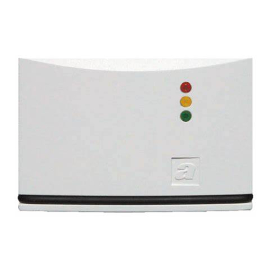
- Page 2 INTRODUZIONE AF904RR è un ricevitore universale ad un canale, accessorio del sistema di allarme via radio. Dialoga con tutti i vari trasmettitori del sistema, telecomando AF939R, rive- latore IR-P AF968R e rivelatore perimetrale multifunzioe AF913R. In funzione del trasmettitore al quale viene associato, assume differenti modalità...
-
Page 3: Caratteristiche Tecniche
CARATTERISTICHE TECNICHE • Contenitore: ABS Bianco (44 x 67 x 19 mm) • Base installabile con viti a parete; apertura per ingresso cavi sul fondo • Coperchio fissato a scatto su base • Alimentazione: da 10 a 14 Vcc • Assorbimento: minimo 17mA, massimo 32mA a 13,8V in dipendenza dallo stato di funzionamento •... -
Page 4: Riferimenti Normativi
RIFERIMENTI NORMATIVI • Sezione radio: I-ETS 300 220 e CEPT T/R 01-04. • Antiintrusione: CEI 79-2 per quanto applicabile. • Omologazione Ministero delle Poste e Telecomunicazioni. DESCRIZIONE FUNZIONAMENTO Programmazione dei trasmettitori 1) Applicare la tensione di alimentazione all’apparecchio mantenendo pre- muto il pulsante RESET. - Page 5 • Rivelatori AF968R e AF913R: fornire alimentazione al rivelatore tramite l’apposita pila. Alla prima alimentazione ogni rivelatore trasmette il pro- prio codice per 30s, questo permette al ricevitore di memorizzare il codi- ce del rivelatore. 5) L’accensione fissa di L2 per 2s conferma l’avvenuta memorizzazione dei codici.
- Page 6 5) Premere ancora Reset per uscire dalla programmazione. Possibilità d’utilizzo AF904RR dispone di due relè (denominati relè A e relè B) e di 3 LED. In funzione del trasmettitore al quale viene associato, si ottengono le seguen- ti possibilità d’impiego.
- Page 7 Inseritore bistabile comandato da telecomando AF939R (ponticello Jp chiuso). Fig. 1 Relè Tamper – Relè Reset Memorizzando il telecomando AF939R, è possibile ottenere il funzionamen- to descritto in tabella.
- Page 8 Stato Azione Contatti 1° Pressione Pressione e LED Alimentazione pulsante rosso pulsante verde Contatto N° 3 impulsi in N° 1 impulsi in aperto relè A chiusura, poi aperto chiusura, poi aperto Contatto aperto (condizione chiuso (condizione chiuso relè B di impianto inserito) di imp.
- Page 9 Ricevitore di segnali di allarme intrusione e/o manomissione (ponticello Jp aperto). Fig. 2 Allarme intrusione Allarme manomissione All'ingresso Tamper della centrale via filo All'ingresso di una zona della centrale via filo Alimentazione dalla centrale via filo – Memorizzando rivelatori AF968R e/o rivelatori AF913R, è possibile inserire rivelatori via radio in impianti realizzati con centrali via filo, come di seguito...
- Page 10 specificato. • In caso di trasmissione del segnale d’allarme intrusione da parte del rivela- tore, il contatto del relè B segnala lo stato di allarme come di seguito spe- cificato. • In caso di trasmissione del segnale d’allarme manomissione (tamper), il contatto del relè...
- Page 11 Quando il contatto del relè B è aperto L1 è acceso. Centrale di allarme monozona via radio (ponticello Jp chiuso) Memorizzando un telecomando ed alcuni rivelatori radio, AF904RR può assumere, come indicato in fig. 3 , le funzioni di una centrale monozona via radio, dove: •...
- Page 12 Stato Contatto Contatto Azione rivelatore relè A relè B Rosso Giallo Verde 1° Aliment. aperto chiuso spento spento acceso Pressione N.°3 impulsi pulsante rosso: in chiusura, chiuso spento acceso acceso centrale inserita poi aperto Condizione aperto chiuso spento acceso acceso di riposo Allarme aperto...
- Page 13 MORSETTIERA Morsetto / Descrizione Ponticello Positivo alimentazione Negativo alimentazione Contatto N.A. relè B Contatto N.A. relè A Ponticello predisposizione tamper. Abilita o esclude il tamper antiapertura. È collegato in serie al contatto del relè A...
- Page 14 Fig. 3 MORSETTO DI COLLEGAMENTO TROMBA ACUSTICA MORSETTO DI COLLEGAMENTO TROMBA ACUSTICA MORSETTO DI COLLEGAMENTO LAMPEGGIATORE A FLASH MORSETTO DI COLLEGAMENTO LAMPEGGIATORE A FLASH ALIMENTAZIONE + ALIMENTAZIONE – MICROINTERRUTTORE ANTIMANOMISSIONE (TAMPER) MICROINTERRUTTORE ANTIMANOMISSIONE (TAMPER) COMANDO SIRENA NC AL POSITIVO COMANDO FLASH NC AL POSITIVO –...
- Page 15 AF913R E AF913R-M RIVELATORE PERIMETRALE MULTIFUNZIONE Fig. 4...
- Page 16 Caratteristiche tecniche • Alimentazione: pila alcalina 9V - standarad size 6LR16 oppure pila al litio SAFT 9V • Assorbimento: 18µA in stand-by - 20 mA in trasmissione • Autonomia: con pila alcalina 18 mesi - con pila al litio 30-36 mesi •...
- Page 17 Descrizione funzionamento Il rivelatore AF913R ha la possibilità di essere utilizzato in varie funzioni ope- rative, selezionabili tramite appositi microswitch. Come indicato in fig.1, è equipaggiato internamente con un contatto reed (ad ampolla) azionato da un magnete esterno, fornito in dotazione, per essere installato a protezione di porte e finestre.
- Page 18 Questa funzione è escludibile con il microswitch 4. Il rivelatore AF913R permette inoltre di trasmettere in centrale lo stato di un contatto NA o NC collegato esternamente. Collegando quindi opportunamen- te, come indicato in fig.4, il contatto di uscita di un qualsiasi tipo di rivelatore (riv.
-
Page 19: Installazione
La trasmissione di uno stato d’allarme è visualizzata dal LED sul corpo del rivelatore. La tabella di pag. 19 illustra le possibilità di utilizzo del rivelatore AF913R e la relativa predispozione. Installazione Aprire il rivelatore facendo leva con un cacciavite sull’anello di chiusura. Fissare sul muro o sull’infisso il corpo del rivelatore, con viti ove utilizzata la protezio- ne antiscasso. - Page 20 IMPIEGO PREDISPOSIZIONE Fissare il magnete (in dotazione) sulla porta o finestra da pro- teggere, ed il rivelatore AF913R sull’infisso. Selezionare se desi- derata la funzione di fine allarme tramite il microswitch 3: ON = fine allarme abilitato OFF = fine allarme disabilitato. Protezione Può...
- Page 21 AF968R RIVELATORE IR-P - Fig. 5 150° 10 m 15 m Caratteristiche tecniche • Alimentazione: pila alcalina 9V - standarad size 6LR16 oppure pila al litio SAFT 9V...
- Page 22 • Assorbimento: 18µA in stand-by - 20 mA in trasmissione • Autonomia: con pila alcalina 18 mesi - con pila al litio 30-36 mesi • Posizionamento: fissaggio a parete, meglio ad angolo, ad una altezza di 2- 2,30 m • Area protetta: apertura 100° per 12m di portata - 20 fasci sensibili su 3 piani •...
- Page 23 Descrizione funzionamento Dopo 3 minuti dal collegamento della pila, il rivelatore è pronto a funzionare. Rilevato un movimento dà luogo a una trasmissione dall'allarme. Per ridurre il consumo della pila, dopo l'allame si hanno 2 minuti di blocco. Nota: In condizioni di riposo, il LED è sempre spento; si accende solo quan- do il rivelatore è...
- Page 24 Allarme manomissione In qualunque momento, aprendo il contenitore dell’apparecchio si ha la tra- smissione dell’allarme manomissione. Allarme per pila scarica La necessità di sostituzione della pila è segnalata da 3 beep, emessi dal rive- latore congiuntamente alla segnalazione di allarme oltre un mese prima della scarica totale.
-
Page 25: Technical Features
INTRODUCTION AF904RR is a one-channel universal receiver, supplied as an accessory of the radio alarm system. It communicates with all the transmitters of the system, the AF939R remote control, the AF968R PIR detector and with the multi-function door-window detector. Depending on the transmitter which it is connected to, it has different ope- ration modes. -
Page 26: Reference Standards
• Current demand: minimum 17mA, maximum 32 mA at 13,8 V depending on the operation mode • 2 normally energised connection relays (positive protection) • Range of the relay contacts: max. 500 mA at 14 Vcc • Grade of the radio section - Carrier frequency: 433.92 MHz - LPD class 1 •... -
Page 27: Operation
OPERATION Programming the transmitters 1) Apply voltage while keeping the RESET push-button pressed. The device memory is cleared. 2) L3 switches on to indicate that power is on. 3) Release the reset push-button. L2 blinks (learning code mode) 4) Programme the transmitters as described below. •... - Page 28 5) Press reset push button again to quit programming. Applications AF904RR has two relays (called relay A and relay B) and 3 Leds. Depending on the transmitter which it is connected to, it has different applications. Note 2: the contacts of the relays are of the NO type, that-is, they close when...
- Page 29 Bistable circuit-closing switch controlled by the AF939R remote control (Jp jumper closed). Fig. 1 Relè Tamper – Relè Reset...
- Page 30 By programming the AF939R remote control, the operations shown in the tab. below will be carried out. Status of Action LEDs and 1 st Press Press contacts supply red push-button green push-button Contact N° 3 closing impulse, N° 1 closing impulse, open relay A then it opens...
- Page 31 Receiver of intrusion and/or tampering alarm signals (Jp jumper open). Fig. 2 Intrusion alarm Tamper alarm To Tamper input of the wired control panel To input of one area of the wired control panel – Power from the wired control panel By programming the AF968R and/or the AF913R detectors, the radio detec-...
- Page 32 tors can be connected to the wired control panel systems as indicated below. • If the intrusion alarm signal is transmitted by the detector, the contact of relay B reports the alarm condition as described afterwards. • If the tamper alarm signal is transmitted, the contact of relay A opens for 2 seconds.
- Page 33 When the contact of relay B is open, L1 is on. One-zone radio alarm control panel (Jp jumper closed) By programming one remote control and some radio detectors, the AF904RR can act as a one-zone radio control panel as shown in picture 1: •...
- Page 34 Detector Contact Contact Operation state relay A relay B Yellow Green 1° supply open closed Press red N.°3 push-button of closing impulse, closed remote control: then it opens control panel On Quiscent state open closed Intrusion open open alarm for 3 min for 3 min Tamper alarm (even if...
-
Page 35: Terminal Board
TERMINAL BOARD Terminal / Jumper Descrizione Positive power Negative power N.O. contact, relay B N.O. contact, relay A Jumper for tamper. It enables or disables the anti-opening tamper. It is series-connected to the contact of relay A. - Page 36 Fig. 3 Terminal for connection of acoustic horn Terminal for connection of acoustic horn Terminal for connection of flash indicators Terminal for connection of flash indicators Power + Power – Anti-tamper micro-switch Anti-tamper micro-switch Siren control NC to positive Siren control NC to positive –...
- Page 37 AF913R E AF913R-M MULTI-FUNCTION DOOR/WINDOW DETECTOR Fig. 4...
- Page 38 Technical features • Power: alkaline battery 9 V - standard size 6LR16 or lithium battery SAFT • Current demand: 18µA during stand-by – 20 mA during transmission. • Life: 18 months with an alkaline battery – 30 to 36 months with a lithium battery.
- Page 39 Operation The AF913R detector can carry out various operational functions which can be selected by means of special micro-switches. As indicated in Figure 1, it is provided with a REED contact operated by an external magnet supplied with the device which must be installed to protect doors and windows.
- Page 40 mitted to the control panel. This function can be desabled by means of the micro-switch 4. By the AF913R detector, the state of an externally connected NO or NC con- tact can be transmitted to the control panel. Therefore, if the output contact of a detector of any kind (temperature detector, water detector, inertial detec- tor for roller shutters, etc.) is properly connected, the control panel can recei- ve the corresponding alarm signal.
-
Page 41: Installation
Installation Open the detector by levering on the fastening ring by means of a screwdri- ver. If the intrusion protection is used, fasten the detector body on the wall or the frame by means of screws. Use silicon and not the adhesive tape if it is installed on glass. Tampering alarm At any moment by opening the enclosure, the tampering alarm is transmit- ted by the corresponding micro-switch. - Page 42 LOCATION Place the magnet (provided with the device) on the door or the win- dow to protect while the AF913R detector must be placed on the frame. If you want, you can select the function of end of alarm by means of micro-switch 3: ON = end of alarm enabled OFF = end of alarm desabled.
- Page 43 AF968R P-IR DETECTOR Fig. 5 150° 10 m 15 m Technical features • Power: alkaline battery 9 V – standard size 6LR16 or lithium battery SAFT 9 V.
- Page 44 • Current demand: 18µA during stand-by – 20 mA during transmission. • Life: 18 months with an alkaline battery – 30 to 36 months with a lithium battery. • Position: Wall-mounting, better if in a corner at a height of 2 to 2,5 meters. •...
- Page 45 Operation 3 minutes after connecting the battery the detector is ready to start. If a movement is detected, it starts the alarm. To reduce the battery current demand, the alarm is followed by a pause of two minutes. Note: In a quiescent condition the LED is always off. It switches on only if an alarm is detected or during the test.
- Page 46 Alarm of battery discharged 3 beeps produced by the detector together with the alarm signal indicate that the battery needs to be replaced one month before its complete discharge. DIRECTIONS The products must be sold in their original packing. Where this is not the case, the retailer and/or the instal- ler must apply and transmit the instructions for use supplied with the product to the user.
Need help?
Do you have a question about the AF904RR and is the answer not in the manual?
Questions and answers