Table of Contents
Advertisement
Quick Links
Realiser A16 User Manual
Stephen Smyth
User Manual v2.0 for A16 firmware v2.05
10/20/21
The Realiser A16 firmware may be updated from time to time to fix bugs, make improvements, and add new features. This manual conforms
to firmware revision 2.05 (20 October 2021). Please check regularly at:
updates going forward. Please note there may be significant differences between the operation described here and that for other firmware
versions.
Contents
1
2
2.1.1
2.1.2
2.1.3
2.2.1
2.2.2
2.2.3
2.3.1
2.4.1
2.4.2
2.4.3
2.4.4
3
3.1.1
3.1.2
www.smyth-research.com/downloads
for firmware and user manual
10
10
10
11
11
15
15
16
18
19
23
24
24
24
24
6
8
8
8
8
9
9
9
Advertisement
Table of Contents

Related Manuals for Smyth Research Realiser A16

Summary of Contents for Smyth Research Realiser A16
-
Page 1: Table Of Contents
User Manual v2.0 for A16 firmware v2.05 10/20/21 The Realiser A16 firmware may be updated from time to time to fix bugs, make improvements, and add new features. This manual conforms to firmware revision 2.05 (20 October 2021). Please check regularly at: www.smyth-research.com/downloads... - Page 2 3.1.3 Loading and running Presets 3.1.4 Displaying the Speaker Map for User A preset 3.1.5 Displaying the Input Level Meters for User A 3.1.6 Displaying the Headphone, Tactile and Bass Level Meters for User A 3.1.7 Listening to the Internal Audio Test Loop Menu Navigation The Home Page menu Navigating the menus, selecting options and changing values with the remote control...
- Page 3 6.3.3 Copy to SD card menu and Delete menu 6.3.4 Copy from SD to internal file 6.3.5 Changing the PRIR filename, subject and layout HPEQ files menu 6.4.1 Phones, Subject, Time 6.4.2 Content 6.4.3 Copy to SD card menu and Delete menu 6.4.4 Changing the HPEQ filename, subject and layout APPs (applications)
- Page 4 10.2.3 Set the Listening Mode Select virtual speakers for a Listening Mode from a PRIR file 10.3.1 Select one matching speaker 10.3.2 Select all matching speakers 10.3.3 Normalise speaker volumes Set Bass Management / Tactile outputs / Stereo mixdown outputs 10.4.1 Dolby Atmos and DTS:X listening rooms 10.4.2...
- Page 5 Configure the A16 for an automatic HPEQ measurement of normal headphones. 13.2.1 Connect the SVS microphones to the A16 13.2.2 Set the headphone A output gain 13.2.3 Connect headphones to the User A HP jack Configure the HPEQ options 13.3.1 Set the Subject name and Headphone name 13.3.2 Set the HPEQ measurement options...
- Page 6 Graphical representation of speaker positions: loudspeaker names and ID numbers Appendix C: Calibrating the magnetic sensor in the head-top device Appendix D: Setting up the head-tracker Appendix E: Updating the Realiser A16 firmware Appendix F: Updating the A16 Head tracker Firmware Appendix G: Head Tracker Thermal Calibration...
-
Page 7: Safety
1 Safety IMPORTANT SAFETY INSTRUCTIONS READ BEFORE OPERATING EQUIPMENT • Read these instructions. • Keep these instructions. • Heed all warnings. • Follow all instructions. • Do not use this apparatus near water. • Clean only with a dry cloth. •... - Page 8 • Lay all connection cables so that they do not present a trip hazard. • Check whether the specifications comply with the existing mains supply. Serious damage could occur due to connecting the system to the wrong power supply. An incorrect mains voltage could damage the equipment or cause an electric shock. •...
-
Page 9: Introduction
2.1.1 The Problem: Listening to multichannel audio over headphones. The Realiser A16 has been designed primarily to allow multichannel immersive audio to be heard accurately through stereo headphones. Today, almost all immersive audio content is monitored over loudspeakers during production, not through headphones, and therefore loudspeaker reproduction, in an acoustically controlled room, is the preferred method for listening to immersive audio. -
Page 10: Realiser A16 Specifications
Optional auxiliary 16ch DANTE 2U version 2.1.3 Realiser A16 specifications SVS loudspeaker virtualisation with integrated headtracking (16ch 32bit floating-point processing@48kHz sampling rate, processing latency 32ms, maximum reverb length 750ms). All source signals above a sampling rate of 48kHz are down sampled to 48kHz. -
Page 11: Presets
2.2.1 Presets User presets contain three types of virtual listening rooms, Atmos, dts:X and PCM. Atmos rooms are intended to be used when a Dolby bitstream is being decoded, or when PCM audio is being up mixed by Dolby Surround. Dts:X rooms are intended to be used when a DTS bitstream is being decoded, or when PCM audio is being up mixed by Neural:X. -
Page 12: Unpacking And Parts Assembly
The Realiser A16 package contains the items below. Main processor components: 1. Realiser A16 processor (either the 2U 19” rack-mountable version or the HS version) 2. Power Supply (input 100-240V AC, 50/60 Hz, output 12V DC @ 3A) 3. IR remote control Set-top head-tracking components: 4. - Page 13 Realiser A16 HS version Universal power supply (100-240V, 50/60Hz) Remote control (IR) 2.3.1.2 Unpacking: Set-top head-tracking components Set-top IR reference for head-tracking Set-top cable (3.5mm plug to 3.5mm plug, 4-pole) Set-top extension cable (3.5mm socket to 3.5mm plug, 4-pole) 12 |...
- Page 14 2.3.1.3 Unpacking: In-ear measurement microphone components Lanyard (for supporting microphones during measurements) Microphone cable support clip (connects to the lanyard and provides strain relief to the microphones when inserted in the ear canals) In-ear SVS measurement microphones (one pair) Ear foam (seals the SVS microphones when inserted in the ear canal – 4 pairs in 3 sizes) 13 | P a g e...
- Page 15 Grounding wrist-strap (used during SVS microphone use to protect against static discharge damage) Head tracker Head-band 2.3.1.4 Unpacking: Head-top head-tracking components Head-top head-tracking device Clip for mounting the head-top device (connects to the headphone head-band) Rubber bands (3 sizes) (connects the clip to a headphone head-band) 14 | P a g e...
-
Page 16: Part Names And Functions
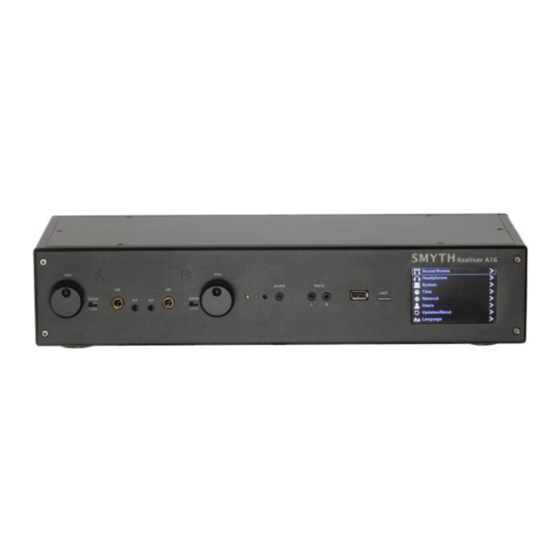
Cable clips to connect the head-top cable to the headphone cable (3 sizes for circular headphone cables, 2 sizes for flat headphone cables) 2.3.1.5 Unpacking: Optional accessories 19” rack-mount ears (for the 2U version of the Realiser A16) Part Names and Functions 2.4.1 Front panel of the Realiser A16-2U... -
Page 17: Rear Panel Of The Realiser A16-2U (Standard Auxiliary 16Ch Single-Ended)
VOL knob for User A headphone output – a digital gain control for the headphone A output. This knob also operates as a momentary push switch. NOTE: The Realiser A16-HS front panel has the same elements listed above, in a vertical and horizontal orientation. 2.4.2 Rear panel of the Realiser A16-2U (standard auxiliary 16ch single-ended) - Page 18 Tactile Out – line-level low-frequency output signals for connection to seat-shakers or stereo subwoofers (2 x RCA sockets) Stereo In – analogue line-level stereo audio inputs (2 x RCA sockets) NOTE: The standard Realiser A16-HS rear panel has the same elements listed above, in a vertical and horizontal orientation. 17 |...
-
Page 19: Realiser A16 Remote Control
2.4.3 Realiser A16 Remote control Power ON/OFF CAL / SPK / HP (only used for PRIR and HPEQ measurements) Solo/mute individual speakers (re-configurable) Engage ALL speakers Engage SVS Headphone mode (switch OFF SOLO mode / (SVS headphone icon key) toggle MUTE mode ON/OFF) -
Page 20: Head-Tracker: Head-Top And Ir Reference Set-Top
2.4.4 Head-tracker: Head-top and IR Reference Set-top 2.4.4.1 Head-Top The Head-Tracker Head-Top connected to a pair of headphones. 19 | P a g e... - Page 21 The Headphone and head-tracker head-top connected to the Realiser via the ports in the front panel. 2.4.4.2 IR Reference Set-top Set-Top powered up Set-Top connected to the Realiser via the Set-top port on the rear panel. 20 | P a g e...
- Page 22 2.4.4.3 Binaural microphones The binaural microphones used to create a PRIR 21 | P a g e...
- Page 23 Binaural Microphone in ear Binaural Microphones in use. The Microphones connected to the Realiser The wrist strap connected to ground. The wrist strap worn during a binaural reading. 22 | P a g e...
-
Page 24: Quick Start
Quick start 1. Connect an BD or DVD player (or other HDMI source) to HDMI Input 1 and a TV monitor to the HDMI Out 2. Connect the 9-12V DC power supply to the A16. 3. Power up the A16, using the remote control if necessary. The A16 will initially display a splash screen, then show presets loading, and finally display a preset Speaker Map for User A. -
Page 25: Initial Power Up
3 Initial power up Power On Sequence During power up the A16 goes through a sequence of hardware and firmware tests that are shown on the LCD display. The sequence for a successful power up is: 1. Splash screen display 2. -
Page 26: Displaying The Input Level Meters For User A
3.1.5 Displaying the Input Level Meters for User A Pressing the green PA key on the remote control displays more typical input level meters showing the digital signal levels that are present at the inputs to the virtual speakers. In this screen capture all sixteen audio signals are active. Input signal levels for User A 3.1.6 Displaying the Headphone, Tactile and Bass Level Meters for User A Pressing the green PA key again displays the output level meters showing the digital signal levels that are present on the SVS processor... - Page 27 The TEST, MUTE and SOLO modes are useful diagnostic tools for checking the normal operational modes of the Realiser A16. The music loop can be changed to a pink noise signal under the audio settings menu.
-
Page 28: Menu Navigation
The Home Page is the root menu for the A16 and gives access to all functions and configuration pages of the A16. The Home Page can be accessed from any other menu using the BACK key repeatedly. The Realiser A16 home page. Navigating the menus, selecting options and changing values with the remote control 4.2.1 Menu option selection:... -
Page 29: Moving Between Menu Levels Using The Enter And Back Keys
4.2.2.2 Graphical values: Use the ADJ+ or ADJ- keys to toggle a switch ON or OFF Value selector using an on/off toggle button 4.2.2.3 Text entry values: 1. Use the ENTER key to create a text-entry cursor in the value select box. ... -
Page 30: Changing Presets From The Speaker Map Page
press. Further presses rotate between these three displays. Whilst in the Speaker Map, Input Level Meter or Output Level Meter pages, either the MENU key or the BACK key will return the user to the previously displayed menu. Speaker Map Speaker Map Input level meters Input level meters... - Page 31 The azimuth angles for both User A and User B head trackers are shown. The current head tracker firmware revision and the hardware revision is also shown for both. Press HT key to return to the speaker map display. 30 | P a g e...
-
Page 32: Settings
5 Settings The Settings menu is accessed from the Home Page menu and is used to set or view configuration data that seldom bb changes. Settings menu Settings option in the Home Page menu PRIR Sound Rooms PRIR sound rooms describe rooms that you intend to capture during a PRIR (ALL) measurement. Two are provided in case there is more than one setup to be captured. -
Page 33: Prir Room 1 Loc
For example, if a virtual speaker is labelled as Lh (Left height) it can be seen from Appendix B: Table 4 that this name is not used in any Dolby Atmos configuration that can be rendered by the Realiser A16. Therefore, a virtual speaker labelled as Lh in any PRIR file will not be matched to a decoded audio output channel when listening to any Dolby Atmos encoded bitstream. -
Page 34: Headphones
5.1.3.9 HPF HPF is not presently used and can remain at the factory setting. Headphones Phones 1-4 describe headphones that you intend to equalize during a HPEQ measurement. Four are provided in case the user wishes to measure more than one model on a regular basis. This menu allows the user to set descriptors for the four different headphones using the alpha-numeric keyboard to insert text. -
Page 35: Ht Settings
5.3.2 HT Settings The Head-tracker consists of a head-top device (placed on the headphones) and a set-top device that normally sits on top of a monitor or TV, centrally. The head-top device has three tracking elements: inertial (gyro), magnetic and optical. The inertial element is the primary means of tracking the rotation of the listener’s head through a full 360 degrees, with either the magnetic or optical elements being used to stabilise the inertial tracking –... -
Page 36: Measurement Settings
5.3.2.3 AB Demo mode Normally set OFF. When set ON the tilt angle of the head-top can be used to trigger the A16 to switch between headphone and speaker outputs (AV mode). This is useful for comparing virtual and real loudspeakers immediately after a PRIR has been measured, but during normal playback this can be distracting. - Page 37 certain situations it is useful to be able to reduce or increase the loudness of the voice prompts. This control does not affect the loudness of the sine sweeps – only the loudness of the voice prompts. 5.3.3.6 Mic Type Normally set to A16.
-
Page 38: Audio Settings
5.3.4 Audio settings Audio settings menu 5.3.4.1 Max HP Vol These set the maximum headphone output volume for User A and User B. 5.3.4.2 Max Vol line Sets the maximum Multichannel Line Output volume for audio playback during AV playback mode or during A/B switching mode. This does not affect the volume of the sine-wave sweeps output during a synchronous PRIR measurement which are set by the Max Sweep Vol set in the Measurement Settings menu 5.3.4.3 HPB->A... -
Page 39: Misc Settings
5.3.4.6 Block mute Block mute is a legacy function that bypasses the muting function of the APM89L decoder board. Due to an error in the A16 muting logic, when changing tracks (BluRay, DVD, CD) a sharp click can sometimes be heard in the headphones/line output just as a track is interrupted and just before a track begins to play. - Page 40 5.3.5.1 SVS 24ch For A16 models that incorporate the APM110 decoder sub-assembly a single user 24 channel Atmos decoding, Dolby Surround up-mixing and SVS rendering mode is supported. Please note that PCM decoding over HDMI remains limited to 7.1 speakers, but can, if desired, be up mixed to a higher channel format using the Dolby Surround up mixer included in the APM110.
- Page 41 Bass management for 24-ch rooms also includes an additional 4 pairs of speakers. Tactile configuration for 24-ch rooms also include 8 additional speakers. 40 | P a g e...
- Page 42 Also for Stereo Mix Down configuration. The speaker map for 24 ch mode. The 24 ch input level meter display. 5.3.5.2 Tone Gen To aid decoder speaker identification the Tone Gen feature of the APM89L/APM110 decoder subassembly can substitute decoder audio with known tones.
-
Page 43: Hdmi Settings
when an HDMI input is receiving active content and will mute anytime this HDMI stream is interrupted. Hence it is necessary to select HDMI(1- 4) before enabling this feature and then play any content with a 48kHz soundtrack to this same HDMI input to active the tones. The tone generator function has two modes of operation. - Page 44 5.3.6.1 Source All non-HDMI audio sources are listed, and each can be given a different assignment. 5.3.6.2 HDMI input Each source should be allocated an HDMI input. The default assignment is HDMI 1. 5.3.6.3 Audio bypass When enabled, this switches the HDMI audio signal as well as the HDMI video signal. 5.3.6.4 HDMI(4) Direct PCM input When enabled PCM audio input over HDMI (4) can be routed directly to the SVS processing, bypassing the APM89L/110 decoder board entirely.
-
Page 45: Full Factory Restore
5.3.7 Full factory restore When enabled, this will restore the A16 to the factory default settings. This includes all the configuration data, all the Listening Rooms and all Presets for both users. It also erases any PRIR and HPEQ measurement data from the circular memory buffers. However, PRIR and HPEQ files in permanent memory are not erased. -
Page 46: Updates/About
NOTE: Full details for updating the A16 with new firmware are given in the appendices: Updating the Realiser A16 Firmware. 5.7.2 Generate log file This generates a small 1 kbyte file and writes it to the Realiser folder of an SD-card. - Page 47 Restore factory setup menu: Warning message 46 | P a g e...
-
Page 48: File Management
6 File Management Files menu (PRIR and HPEQ) On the Home Page menu, the PRIR/HPEQ file menu is accessed through the Files option. Home Page menu: Files menu File menu showing the number of PRIR and HPEQ files in each location. Memory locations Permanent internal storage for PRIR and HPEQ files. -
Page 49: Location
Selecting a PRIR file external SD card. 6.3.1 Location This is the name of the room where the PRIR was measured. If a photograph of the room is attached to the PRIR it can be viewed using the ENTER key. Image of the room in which the PRIR was measured. -
Page 50: Changing The Prir Filename, Subject And Layout
The SD card reader always checks if the user has permission to use the PRIR file being copied into their A16. If the PRIR is locked to another A16, the file transfer is abandoned, and an authorisation warning displayed. 6.3.5 Changing the PRIR filename, subject and layout The filename, layout and subject fields of internal and recycle PRIR files can be edited using the standard text entry method up to a maximum of 32 characters for each. -
Page 51: Copy To Sd Card Menu And Delete Menu
6.4.3 Copy to SD card menu and Delete menu HPEQ files may be copied from permanent storage or the recycle buffer to an external SD card (when inserted). PRIR files may also be deleted from permanent storage – but cannot be deleted from the external micro-SD card or the recycle buffer. Use a computer to delete files from a micro-SD card. -
Page 52: Apps (Applications)
7 APPs (applications) APPS or applications are routines that generally run on the A16 in place of the regular decoding/SVS rendering system. This means that the normal operation of the A16 may be suspended while any application program is running. Subject-Room-Phones The ‘Subject’... -
Page 53: Audio Source Selection
8 Audio Source Selection Audio Sources that can be selected are as follows; eARC (where the HDMI board is present) HDMI 1 input HDMI 2 input HDMI 3 input HDMI 4 input Line (or AES-EBU where the digital auxiliary board is present) SPDIF Co-axial SPDIF Optical The audio source selection is controlled in the home page when the global slider is enabled. -
Page 54: Configuring A Preset For Svs Headphone Or Av Mode
9 Configuring a Preset for SVS headphone or AV mode The primary purpose of a Preset is to select personalised Listening Rooms and Headphone EQ filters for an individual listener. Presets bring together Listening Rooms (which contain PRIR data), configuration data and user information and are the gateway for running the headphone virtualisation process of the A16. -
Page 55: Select The Preset Number
User A Preset Menu page 2 9.2.1 Select the Preset number For each username sixteen different presets can be configured and saved internally. The factory default initially stores the same 16 presets for Users 1 thru 8 for both listener A and B. Use the ADJ+ and ADJ- keys to select an individual preset, for activating or to change the configuration of the preset. -
Page 56: Toggle The Av Mode On Or Off
9.2.6 Toggle the AV mode ON or OFF Normally set OFF. When set OFF this Preset, when active, will not allow audio to be output to the 16-ch line outputs, and can only be used for SVS headphone rendering of decoded audio. When set ON this Preset, when active, allows decoded audio to be output to either the 16-ch line outputs or to be rendered to the SVS headphone outputs. -
Page 57: Pcm Audio Management
9.2.8 PCM Audio management PCM Audio management is an option found on the second page of the Preset configuration page for User A. This option leads to the PCM Audio Management menu and configures the A16 to optionally either up-mix or pass-thru PCM audio signals from the HDMI or SPDIF inputs. For all other input types the up mixer option is not available. -
Page 58: Dts Night Mode
and where the number of speakers in the listening room is different to that of the decoded bit stream, up or down mixing will be applied automatically. 9.2.14 DTS Night mode This option limits the dynamic range of the decoded DTS:X output signals. When disabled full dynamic range is preserved. When enabled the dynamic range of the audio is reduced. -
Page 59: The Pa And Pb Key
original preset, without changing the active preset. The changes will only take effect when the modified preset is loaded and activated. If changes are made in the currently active preset the user is prompted to RELOAD the preset. Note: Changes to a preset involving operation of the head tracker (and some other real-time parameters) will take effect instantly, without needing to reload the preset. -
Page 60: Elements Of The Speaker Map Display For Any Preset
The output level meters also indicate the peak PCM audio levels internal to the SVS rendering DSPs. Green levels meters signify these are signals that are output from the SVS rendering DSPs. Brown level meters signify these signals remain inside the SVS rendering DSPs but can be mixed in to form part of an output signal. - Page 61 SVS Movie mode changing the volume for either user also changes the Speaker Map display to show the active preset for that user. The headphone outputs of User A and User B can be muted independently using the MUTE toggle keys. Volume for User A headphone output Volume for User B headphone output 9.4.4.2 Line output volume control in AV mode...
- Page 62 The azimuth angles for both User A and User B head trackers are shown. The current head tracker firmware revision and the hardware revision is also shown for both. Press HT key to return to the speaker map display. NOTE: Headtracking is only active if presets for user A and user B are loaded and active. 9.4.4.6 SOLO Mode: solo individual speakers in SVS Movie (headphone) or AV (loudspeaker) modes Whilst in the Speaker Map display individual loudspeakers can be soloed, using the individual speaker keys and the alpha-numeric keys on the remote to solo individual speakers.
- Page 63 9.4.4.9 Increment or decrement the Preset Number While in the Speaker Map display the preset number for user A or B can be changed using the ADJ+ and ADJ- keys to increment or decrement through the list of 16 presets allocated to the currrent named user. This operation takes a few seconds to complete while the new preset is being loaded.
-
Page 64: Building A Listening Room From One Or More Prirs
10 Building a Listening Room from one or more PRIRs Listening rooms are configured to reflect the varying loudspeaker setups of different audio decoding formats, such as Dolby Atmos and DTS:X, and other formats. The individual loudspeakers that make up these formats are matched to personalised room impulse response (PRIR) data that contain virtualised versions of the same loudspeakers. -
Page 65: Set The Listening Mode
10.2.3 Set the Listening Mode Use the ADJ+ and ADJ- keys to adjust the listening mode to the preferred format. Dolby Atmos formats have an additional option for Dolby Enabled speakers which should be set correctly for AV listening if used. The listening mode defines the number and arrangement of speakers for a particular listening room configuration. -
Page 66: Select One Matching Speaker
PRIRs can be selected from permanent storage, the recycle buffer or from the factory PRIR files. Select the desired PRIR file. Any of the PRIR files in each source location can be chosen using the numerical selector at the top of the page. Information that describes each PRIR is also shown to identify and select a particular file. -
Page 67: Select All Matching Speakers
10.3.2 Select all matching speakers This menu option automatically selects all the virtual speakers in the PRIR that match the reference speaker names in the Listening Room, and then returns the system to the Listening Room configuration menu. Information related to the virtual speakers is also displayed. Below illustrate matching virtual speakers in a 7.1.4ch listening room all taken from a single PRIR measurement. -
Page 68: Pcm Listening Rooms
output to real (AV loudspeaker mode) or virtual loudspeakers (SVS headphone mode). This bass management stage can also be by-passed, in which case only the LFE signal is sent to the sub-woofer speaker, real or virtual. For SVS headphone rendering there are two alternative bass management modes (labelled hp) that can be engaged –... -
Page 69: Bass Management For Pcm Listening Rooms
3. Bass management using Direct Bass mode that by-passes the virtual sub-woofer speaker. For AV loudspeaker listening of PCM input signals the Realiser A16 does NOT include options for bass management. It is assumed that bass management will occur after the audio signals are output from the A16. -
Page 70: Stereo (Mixdown)
Tactile output (menu page 1) Tactile output (menu page 2) In the above example, the low-pass filtered components of the L, R, C and SW channels of a 9.1.6ch signal are being mixed, at varying gains, to the 2-ch tactile outputs, Lt and Rt. Some of the low pass filtered signals are being sent to a single output channel (either Lt or Rt) and some are being sent to both channels equally (Lt+Rt). -
Page 71: Stereo Bypass
11 Stereo Bypass When AV mode is disabled in the active User A preset, the headphone key and speaker key switch can alternatively switch between SVS headphone mode and Stereo Mix Down mode, respectively. However, to switch to Stereo mode it must first be enabled in the listening room currently loaded and the corresponding mix down table configured appropriately. -
Page 72: Steps To Listening To Stereo Audio Using A 2Ch Stereo Bypass Method
In the Stereo Mix Down mode, the user can choose to filter the stereo audio using the HPEQ specified in the active User A preset, prior to being output to the headphone. Steps to listening to stereo audio using a 2ch Stereo Bypass method 1) In the current User A preset, disable the AV mode. -
Page 73: Automatic Stereo Bypass For Dts Headphone:x
12) Initially the SVS rendered version of the stereo will be heard over the headphones. Press the speaker key on the remote to hear the raw stereo. 13) If it is desired to filter the stereo mix down audio using the preset HPEQ, then enable this feature in the PCM listening room editor. 14) If you need to adjust the volume of the stereo mix down audio without altering the SVS rendered volume, adjust the volume in the PCM room 4 Configure menu. -
Page 74: Measuring A New Prir In A Sound Room Using The Synchronous (All) Method
12 Measuring a new PRIR in a sound room using the synchronous (ALL) method There are two methods for measuring PRIRs – the Synchronous (ALL) method and the Asynchronous (ASYC) method. Choosing which method to use will often depend on how easily the A16 can be connected to loudspeaker amplifiers in the listening room that is being measured. Method 1: Synchronous (ALL) –... -
Page 75: Configure The Prir Room 1 Speaker Setup
For example, if a virtual speaker is labelled as Lh (Left height) it can be seen from Table 1 Appendix A, that this name is not used in any Dolby Atmos listening mode that the Realiser A16 is capable of rendering. Therefore, a virtual speaker labelled as Lh in any PRIR file cannot be matched to a speaker in any configuration of a Dolby Atmos Listening Room, and can only be matched in an appropriately configured DTS:X or PCM Listening Room. -
Page 76: Configure The Measurement Settings
12.1.3.6 UF, FF and hpf UF refers to up-firing speakers designed to simulate ‘height’ or ‘top’ speakers by reflecting sound from the ceiling. The speaker’s name should match the spatial direction of the simulated (or reflected) sound – for example a speaker labelled as ‘Ltf’ (Left top front) and described as UF means that this up-firing speaker simulates a speaker in the ‘Ltf’... -
Page 77: Connect The Svs Microphones To The A16
3. Switch the power amplifiers of the loudspeakers back on. 12.1.6 Connect the SVS microphones to the A16 1. Check that the Left and Right microphones are inserted in the L and R MIC sockets in the front panel of the A16. 2. -
Page 78: Run The Speaker Calibration Routine
2. Select the speakers to be calibrated by entering the Speaker select menu option. Move to: Home Page menu: Apps menu: Calibrate speakers (CAL) menu: Speaker select menu The listed speakers will match the configuration of the selected PRIR Sound Room and all speakers will be switched ON by default. Switch OFF any speaker that does not require calibration, then return to the previous menu (BACK key). -
Page 79: Configure And Run The Prir Measurement Routine
and/or • Increase the global external gain of the loudspeaker amplifiers (using an external volume control) then run the calibration routine again. If the SVS mic levels are sufficiently good (at least one green channel for each calibrated loudspeaker) then the speaker calibration for the PRIR measurement is complete. - Page 80 12.3.3.1 Look-azi Look-azi is the azimuth, or rotational, angle of the head. Zero degrees is looking dead-centre. If Look-azi is enabled, the angular span of the look-angle and the number of look-angles must be set. The angular span can be set from +/-5 degrees to +/-60 degrees, in steps of 5 degrees, and the number of look-angles can be set from 1 to 11 but the maximum number depends on the size of the angular span.
-
Page 81: Set The Sweep Type
Pilot axis mode is selected using the left/right arrow key when running the PRIR measurement For either axis, once the head tracker angle moves within 1 degree of the desired look angle, the pilot tone for that axis will mute. Hence, when the head orientation is within 1 degree of the desired look angle no pilot tones will be heard. -
Page 82: Assessing The Impulse Response Quality Between Looks
NOTE: Ensure that the SVS microphones are correctly inserted in each ear canal (left mic in the left ear) and that the subject is in the sweet spot of the room facing towards the centre speaker. To begin the PRIR measurement procedure press the SPK key on the remote control and wait for the verbal instructions. During the measurement, the screen will display the speakers that are being measured, and the signal levels being recorded by the microphones. -
Page 83: Saving The Prir Measurement
12.3.7 Saving the PRIR measurement To save the PRIR measurement press the ENTER key The current PRIR measurement is always saved to the first slot of the PRIR recycle buffer, and other older measurements in the recycle buffer are shuffled up one slot - the measurement stored in slot 16 is overwritten and lost. Therefore, PRIR measurements in the recycle buffer should be moved to the permanent internal storage or to an external SD card. -
Page 84: Measuring Personalised Headphone Hpeq Filters
13 Measuring personalised headphone HPEQ filters Overview of HPEQ methods supported by the A16 Headphone EQ filters are used to try to flatten the frequency response of headphones when placed over a listener’s ears. Because individual’s have different ear shapes and ear canals, they need individualised headphone EQ filters. Up to four different EQ filters can be created within a single HPEQ file, and any one of these four filters can be selected within a preset configuration. -
Page 85: Configure The Hpeq Options
Configure the HPEQ options 13.3.1 Set the Subject name and Headphone name Move to: Home Page menu: Apps menu Apps menu 13.3.1.1 Select a Subject name This name is selected from the list created in the Users Menu (Home Page menu: Settings menu: Users menu). 13.3.1.2 Select the Phones name This name is selected from the list created in the Headphones Menu (Home Page menu: Settings menu: Headphones menu). -
Page 86: Saving The Hpeq Measurement
An initial calibration routine will send short sine sweeps, at increasing volumes, from the left and right drivers of the headphones to find an adequate microphone level. Immediately following the calibration, the measurement routine begins, and a long sine sweep is output first from the left headphone driver and then from the right headphone driver. -
Page 87: Configure The A16 To Generate A Flat Hpeq Filter
Configure the A16 to generate a flat HPEQ filter. 13.5.1 Set the Subject name and Phones name Move to: Home Page menu: Apps menu Selecting the Subject and Headphones names. 13.5.2 Set the HPEQ measurement options Move to: Home Page menu: Apps menu: Headphone EQ (HP) menu Setting the Headphone EQ (HP) menu options. - Page 88 13.6.1.1 Subject, Phones These names are set in the previous menu but are not relevant for the manual EQ stage. 13.6.1.2 Man EQ Start Selects the base filter to be adjusted. The options are autoEQ or flatEQ. 13.6.1.3 Curve The frequency response curve of the band-limited pink noise excitation signal. The options are flat, equal-loudness-80 or equal-loudness-20. 13.6.1.4 Man EQ HPEQ Selects the HPEQ file that contains the filter to be manually adjusted.
-
Page 89: Manual Hpeq Adjustment Using An Equal Loudness Curve
NOTE: The CANCEL key will remove ALL changes and create a flat filter. NOTE: SAVE the filter back to the HPEQ file using the HP key. Once the manSPKR filter has been saved it will be visible as an optional filter in the HPEQ file and can be selected as the HPEQ filter within a preset. - Page 90 Manual EQ changes to a flatEQ filter, using equal loudness sub-band noise signals. NOTE: The objective is to remove any peaks or troughs between the sub-bands, using Band 1 as the reference level. NOTE: The CANCEL key will remove ALL changes and create a flat filter. NOTE: SAVE the filter back to the HPEQ file using the HP key.
-
Page 91: Measuring A Prir Using The Async Method
14 Measuring a PRIR using the Async Method As with the ALL method, the Asynchronous PRIR (ASYNC) method measures the room impulse responses using the SVS microphones placed in the subject’s ears. However, unlike the ALL method, the sinewave sweeps for each look angle are sourced from an external player such as a DVD player or a DAW (DVD/DAW). -
Page 92: Async Preamble Track
14.1.2 Async Preamble track To speed up the configuration of the A16, an Asynchronous Preamble audio track signals to the realiser the format of the pending measurement using DTMF burst tones. Preamble signalling informs the A16 of: 1) the look angles 2) sweep type 3) speaker names 4) speaker format. -
Page 93: Async Level Calibration
Example of PLL 60s tone in a 5.1ch measurement (only the first two channels carry the tone) 14.1.4 Async Level calibration Level calibration is simply a track that outputs a short sinewave sweep to each speaker at the same volume level as the sinewave sweeps used for the main deconvolution. -
Page 94: Async Sweeps For Each Look Angle
14.1.5 Async Sweeps for each look angle Look tracks are generated for each look angle the subject intends to measure and must position their head appropriately before playing the tracks. Look angle measurements can be undertaken in any order and can be repeated as often as necessary with the exception that the right- most look track (or look down of the right-most look track) will complete the measurement. -
Page 95: Async Method Configuration
ASYNC method configuration Before you begin an Async PRIR measurement, one of the PRIR sound rooms, under the settings menu, should be configured to match the real sound room being measured. This sound room, as well as the subject name, should then be selected in ‘Room’ and ‘Subject’ respectively in the Apps home page. -
Page 96: Config Look Angles
With Override preamble IDs enabled, loudspeaker IDs from the selected sound room are copied into the final Async PRIR. In the example below, Sound Room 1 describes a modified 5.1ch speaker layout where C and SW have been replaced by front screen speakers Lsc, Rsc and the surround speakers have been replaced by side surround speakers Lss and Rss. -
Page 97: Performing An Async Measurement
Performing an ASYNC Measurement For this example Async Measurement, we will use the 5.1ch PCM AVCHD file shown below. This 5.1ch measurement suite contains all the tracks necessary to capture a 5.1ch speaker setup for three azimuth angles (centre, left 30 degrees and right 30 degrees) and two elevation angles (up 20 degrees and down 20 degrees) To start the Async PRIR application select Measure Async PRIR in SPK (run) and press enter. - Page 98 On completion of the level calibrate track, play the Phase Locking track (T3). Again, this is automatically detected by the A16. The purpose of this track is to allow the A16 to adjust its sample clock to match that of the players. This adjustment is required to maximize the quality of the resulting PRIR.
-
Page 99: Improving Async Look Angles Using The Head Tracker
By consulting the look grid page, it is easy to recall which looks have been measured and which have not. Note, all future Async measurement files/tracks generated by Smyth Research will be standardised on this look grid. - Page 100 14.3.1.1 Using the Preamble Look angles in conjunction with HT assist. With Look angles set to Fixed the look angles inserted into the PRIR file are simply a copy of those signalled on the preamble track. As a result, it is necessary for the subject to align their head with these look angles prior to each look measurement. Unless the look angles are very simple, having the subject move their head unaided can lead to significant degradation in the accuracy of the look angles and the SVS head tracking experience in general.
-
Page 101: Building A Composite Prir File
15 Building a Composite PRIR file The composite PRIR builder application is a tool to better manage PRIR files in general. The composite builder application can extract up to 35 virtual speakers from pre-existing PRIRs located in the A16’s internal directory and create a new PRIR file comprising these speakers. PRIR speakers that have been created using different look-angle strategies can be loaded to the same composite PRIR without issue. - Page 102 Each channel of the new PRIR is numbered on the left-side of the display. The virtual speaker ID (Vspkr), azimuth angle (Azi) and elevation angle (Elev) is displayed for each. ‘Denoise’ and ‘Swap LR’ operations can also be enabled or disabled for any channel. Move the cursor to the desired channel and press ENTER.
-
Page 103: Denoising Prir Speakers
The routine will build the new PRIR channel by channel, add any selected Bitmap photograph and finally save the new composite PRIR to the A16 recycle PRIR directory. Navigate to ‘FILES’ in the home page and select ‘recycle PRIR files’ to view the new PRIR. If the composite PRIR has just been built, this will be the first file in the directory. -
Page 104: Locked Prirs
This can be fixed by swapping the Vspkr IDs before building the new PRIR. Although not shown here, for the purposes of clarity the user may also wish to swap the azimuth angles to reflect the new positions. Another use is to give duplicated virtual speaker different IDs. In this example the same virtual speaker Ltf is loaded to two channels. By altering the Vspkr ID of one of the channels to Lh, the subsequent composite PRIR is now compatible for both Atmos and dts-X listening rooms. -
Page 105: Listening At Reference Level Over The Headphones
16 Listening at Reference Level over the headphones Movie soundtracks are commonly created in dubbing stages and mixing studios that are calibrated to a particular loudness or reference level. By playing back a movie soundtrack at the same reference level, the listener can replicate the sonic experience that would have been intended by the director during the production. -
Page 106: Setting Up The Reference Level Using A Simple Comparison
Setting up the Reference Level using a simple comparison Setting the reference level in the A16 is essentially the same process. The only difference is that the listening room is a virtual experience in a headphone. Regular SPL meters cannot easily measure the volume levels in your ears. However, one way of overcoming this problem is to use a simple comparative procedure. -
Page 107: Setting Up The Reference Level Using The Cal Spl Method
Using Reference Level SPL for PCM Room By enabling the PCM Ref switch, the A16 will display the volume in reference SPL as opposed to volume units. However, the Preset must be reloaded for this to occur. Using a comparison method is easy to understand and relatively easy to undertake. However, unless the virtual PCM room is a measured copy (PRIR) of the real listening room you are using to make the comparison, the final reference level may only be accurate to within 2 to 3 dB since the spatial and tonal difference between them will make it difficult to achieve anything closer. -
Page 108: Calibrating An Atmos Or Dts:x Room
The SPL calibration routine always starts up with the front left virtual speaker in solo. Since in this example the pink noise is internally generated, the L-R headphone level meters immediately indicate the peak PCM signal level (green bars) heard through the headphones, and this level will rise and fall as the user A volume is adjusted in the normal way. -
Page 109: Estimating Reference Level Headroom
Estimating Reference Level Headroom For any reference level it is critical to know whether the combined signal level of the virtual sound stage at that volume level will have sufficient digital headroom as the input signals approach peak. To help with this calculation a headroom estimation algorithm is used to display yellow headroom bars that ride atop the green headphone peak level bars. -
Page 110: Headphone Spl Headroom
Plug in headphones and SVS microphones Create a Preset for user A that assigns the listening room to be calibrated to the desired room type In that Preset assign a HPEQ file for the headphone you intend to use Ensure AV mode is disabled Load the user A Preset just created Ensure TEST mode is not active Ensure the A16 is running in 16ch SVS mode... -
Page 111: Measuring Binaural Spls For Subwoofers
Measuring Binaural SPLs for subwoofers While running the Cal SPL routine the binaural SPL for the subwoofer can be measured by pressing the remote LFE key. In theory, for a subwoofer (80Hz low pass) set to the same gain as the main speakers, the binaural SPL would be approximately 5dB below that for the main speakers. - Page 112 111 | P a g e...
-
Page 113: Tcp Command Server
The A16 implements a simple TCP based command and response protocol that allows a remote device (client) to control and/or monitor certain operational aspects of the A16 in real time over a home network. Document ‘Realiser A16 IP (TCP) Command Summary, 5 May 2020, S. -
Page 114: Appendix A: Listening Rooms Loudspeaker Configurations
18 Appendix A: Listening rooms loudspeaker configurations Dolby Atmos Listening Rooms loudspeaker configurations (16ch) Line Output Channel Number Mode 2.0.2m 2.1.2m 2.2.2m 3.0.2m 3.1.2m 3.2.2m 4.0.2m 4.1.2m 4.2.2m 5.0.2m 5.1.2m 5.2.2m 5.0.4 5.1.4 5.2.4 5.0.6 5.1.6 5.2.6 6.0.2m 6.1.2m 6.2.2m 7.0.2m 7.1.2m 7.2.4h... - Page 115 7.0.4 7.1.4 7.2.4 7.0.6 7.1.6 7.2.6 9.0.2m 9.1.2m 9.2.2m 9.0.4 9.1.4 9.2.4 9.0.6 9.1.6 Table 1 Supported loudspeaker configurations for Dolby Atmos listening rooms in dual-user (16ch) mode. 114 | P a g e...
-
Page 116: Dolby Atmos Listening Rooms Loudspeaker Configurations (24Ch)
Dolby Atmos Listening Rooms loudspeaker configurations (24ch) Mode 5.0.4h 5.1.4h 7.0.4h 7.1.4h 7.0.6h 7.1.6h 8.0.4 8.0.4h 8.1.4 8.1.4h 8.0.6 8.0.6h 8.1.6 8.1.6h 9.0.4h 9.1.4h 9.0.6h 9.1.6h 9.0.8 9.1.8 10.0.4 10.0.4h 10.1.4 10.1.4h 10.0.6 10.0.6h 10.1.6 10.1.6h 10.0.8 10.1.8 11.0.4 Lrs1 Rrs1 11.0.4h Lrs1 Rrs1 11.1.4... - Page 117 12.0.6h Lrs1 Rrs1 12.1.6 Lrs1 Rrs1 12.1.6h Lrs1 Rrs1 12.0.8 Lrs1 Rrs1 12.1.8 Lrs1 Rrs1 12.0.10 Lrs1 Rrs1 12.1.10 Lrs1 Rrs1 13.0.4 Lrs1 Rrs1 13.0.4h Lrs1 Rrs1 13.1.4 Lrs1 Rrs1 13.1.4h Lrs1 Rrs1 13.0.6 Lrs1 Rrs1 13.0.6h Lrs1 Rrs1 13.1.6 Lrs1 Rrs1 13.1.6h Lrs1 Rrs1...
-
Page 118: Dts:x Listening Rooms Loudspeaker Configurations (12Ch)
DTS:X listening rooms loudspeaker configurations (12ch) Line Output Channel Number Mode 5.0.2f 5.1.2f 5.2.2f 5.0.2m 5.1.2m 5.2.2m 5.0.2h 5.1.2h 5.2.2h 5.0.4t 5.1.4t 5.2.4t 5.0.4h 5.1.4h 5.2.4h 7.0.2f 7.1.2f 7.2.2f 7.0.2m 7.1.2m 7.2.2m 7.0.2h 7.1.2h 7.1.2h 7.0.4t 7.1.4t 7.2.4t 7.0.4h 7.1.4h 7.2.4h 9.0.2f 9.1.2f... - Page 119 9.2.2m 9.0.2h 9.1.2h 9.2.2h Table 2: Supported loudspeaker configurations for DTS:X listening rooms in dual-user mode (12ch). 118 | P a g e...
-
Page 120: Pcm Listening Rooms Loudspeaker Configurations (16Ch)
PCM listening rooms loudspeaker configurations (16ch) Line Output Channel Number Mode 2.2.2t 2.2.2h 3.2.2t 3.2.2h 4.2.2t 4.2.2h 4.2.4t 4.2.4h 5.2.2t 5.2.2h 5.2.4t 5.2.4h 5.2.6t 7.2.2t 7.2.2h 7.2.4t 7.2.4h 7.2.6t 9.2.2t 9.2.4t 9.1.6t Custom#1 Custom#2 Custom#3 Custom#4 Table 3: PCM listening rooms loudspeaker configurations in dual-user mode (16ch) 119 | P a g e... -
Page 121: Appendix B: Loudspeaker Names And Labels
19 Appendix B: Loudspeaker names and labels Loudspeaker names and labels with default azimuth and elevation angles Label Name Azimuth Elevation Atmos DTS:X PCM Custom Left Right Centre Subwoofer Left surround -100 Right surround Left back -120 Right back Left side surround Right side surround Centre rear Subwoofer 2... - Page 122 Left height wide Right height wide Lhs1 Left height side 1 -110 Rhs1 Right height side 2 -110 Left back ground -120 Right back ground Table 4: Loudspeaker names, labels and ID numbers Notes 1. The azimuth and elevation angles are default values – the angles can be changed to match a physical loudspeaker layout during a PRIR measurement.
-
Page 123: Graphical Representation Of Loudspeakers In The Speaker Map Display Of The A16
Graphical representation of loudspeakers in the Speaker Map display of the A16 Lhs1 Rhs1 Lrs1 Rrs1 Lrs2 Rrs2 Ear level Height Overhead Ground Subwoofers 122 | P a g e... -
Page 124: Graphical Representation Of Speaker Positions: Loudspeaker Names And Id Numbers
Graphical representation of speaker positions: loudspeaker names and ID numbers Cg - 21 SW - 4 SW2 - 12 C - 3 Rsc - 38 Lg - 19 Lsc - 37 Rg - 20 Rc - 18 Lc - 17 R - 2 L - 1 Ch - 22... -
Page 125: Appendix C: Calibrating The Magnetic Sensor In The Head-Top Device
20 Appendix C: Calibrating the magnetic sensor in the head-top device Home Page menu: Apps menu: Calibrate head tracker menu: The A16 head-tracker has three motion detecting sensors, inertial, magnetic, and optical. The inertial sensor operates continuously but it can also be stabilised, in a narrow central window, by either the magnetic or optical sensors. - Page 126 If set to HARD the calibration will be less accurate but will take a shorter time to complete. If set to HARD+SOFT the calibration will be more accurate but will take a longer time to complete. Calibrate magnetics Use the ENTER key to run the magnetics calibration routine as outlined above. NOTE: If calibration appears to be taking too long to complete, use the BACK key to terminate the calibration routine.
-
Page 127: Appendix D: Setting Up The Head-Tracker
21 Appendix D: Setting up the head-tracker The head-tracker consists of two parts: 1. A HEAD-TOP part that is mounted on top of a pair of headphones and is connected to one of the two HT ports on the front panel of the A16. The head-top has three tracking sensors, inertial magnetic and optical, and from these is calculated a head-tracking angle that is transmitted back to the A16. - Page 128 Setting up and configuring the head-tracker. This consists of: Step 1. Mounting the head-top to a pair of headphones and connecting this to the HT port on the front panel of the A16. Step 2. Mounting the set-top in some central location (on top of the TV) and connecting this to the Set-top port on the rear panel of the A16. Step 3.
- Page 129 Connecting the head-top cable to the headphone cable using Connect the Head-top cable to appropriate HT port on the clips front panel of the A16 Immediately after connection, the LED on the head-top will momentarily turn RED while it checks the validity of the internal head-tracking program.
- Page 130 2. Navigate to the HT Settings menu Move to: Home page menu: Settings menu: System menu: HT Settings menu: Stabilisation option 3. Set the stabilisation mode to OPTICAL. 4. Point the front face of the connected head-top device towards the set-top. The set-top should quickly indicate a zero-degree heading. At a head-top heading of zero degrees azimuth and zero degrees elevation the four central LEDs (around the IR LED) should all be ON.
-
Page 131: Appendix E: Updating The Realiser A16 Firmware
1. STEP 1. The new firmware for the Realiser A16 is uploaded through the micro-SD card slot on the front panel. First, obtain a micro-SD card (commonly 8 or 16 GB) and ensure it is formatted as FAT32. Second, create a ‘realiser’ folder in the root directory and copy the firmware file FIRMA001.SVS into the realiser folder. - Page 132 Navigate to ‘Restore factory setup’ and press ENTER again. Select ‘full restore’ and press ENTER again. The full restore will take approximately 10 minutes to complete, thereafter the A16 will automatically return to the User A speaker map display. 131 | P a g e...
-
Page 133: Appendix F: Updating The A16 Head Tracker Firmware
23 Appendix F: Updating the A16 Head tracker Firmware Updating the Head Tracker The HT firmware updater programs a head tracker firmware file (FIRMHT01.SVS), held internal to the A16, into the head tracker via the HT cable. This internal firmware file is normally loaded to the A16 as part of a general A16 firmware update and as such is invisible to the user. However, on triggering the HT firmware update process the A16 will first check if such a file exists in the REALISER directory on the micro-SD card. - Page 134 Typical operating steps Step 1) Connect the head tracker to the A16 and turn the A16 on. The LED atop the head tracker will initially turn RED and will blink RED every second if stationary. Step 2) Keeping the head tracker stationary, wait until the blinking led turns GREEN. This may take 5 to 10 minutes. Step 3) Once blinking GREEN the head tracker is ready for use.
- Page 135 flash memory within the head tracker and restored automatically on future power-ups. To disable the offset angle mode of operation press- and-hold the switch atop the head tracker for 0.5 seconds (one short blink on the led). It should be stressed that when setting the offset angle, or operating in an offset location in general, the set-top offset angle should not exceed the stabilisation window range.
-
Page 136: Appendix G: Head Tracker Thermal Calibration
24 Appendix G: Head Tracker Thermal Calibration If the head tracker signals 10 red flashes on power up or has stopped working all together, corruption of its internal thermal calibration data is the likely cause. The head tracker will not function in this state, and it will be necessary to perform a thermal recalibration. The steps are as follow. -
Page 137: Appendix H: Connections
Several different devices can be connected by using one of the 4 HDMI input on the back panel of the Realiser. A list of Devices that are compatible with the Realiser A16 are listed below: • DVD Players with HDMI output •... - Page 138 • Other Smart TV sticks with HDMI output. • HDMI Output on a computer. These devices can be then connected to a monitor via the HDMI output port on the rear panel. This allows the Realiser to connect 4 different devices via HDMI to a monitor or TV via a single HDMI port.
-
Page 139: Appendix I: Bass Management
26 Appendix I: Bass Management Atmos / DTS:X AV bass management ON (HDMI, Coaxial) (HP DB disabled) In this scenario the bass management of the decoded Atmos/DTS:X channels is enabled, and the bass managed low-frequency signal is passed to the virtual sub-woofer for SVS headphone rendering, or to a real sub-woofer for AV loudspeaker listening. Parameters: 1: hp/av LFE +10dB (set ON or OFF) 2. -
Page 140: Atmos / Dts:x Av Bass Management Off (Hdmi, Coaxial) (Hp Db Disabled)
Atmos / DTS:X AV bass management OFF (HDMI, Coaxial) (HP DB disabled) In this scenario the bass management of the decoded Atmos/DTS:X channels is disabled, and the decoded LFE channel is passed to the virtual sub-woofer speaker for headphone rendering, or to a real sub-woofer for loudspeaker listening. Parameters: 1: hp/av LFE +10dB (set ON or OFF) 2: hp/av SW volume (set from +12dB to -30dB) 3: hp/av BM (set OFF) -
Page 141: Atmos / Dts:x Av Bass Management On (Hdmi, Coaxial) (Hp Db Enabled)
Atmos / DTS:X AV bass management ON (HDMI, Coaxial) (HP DB enabled) In this scenario the bass management of the decoded Atmos/DTS:X channels is enabled, but the virtual sub-woofer speaker is NOT used for bass management for SVS headphone rendering. Instead the bass managed low frequency part of the signal, including the decoded LFE channel, is sent directly to the headphones. -
Page 142: Atmos / Dts:x Av Bass Management Off (Hdmi, Coaxial) (Hp Db Enabled)
Atmos / DTS:X AV bass management OFF (HDMI, Coaxial) (HP DB enabled) In this scenario the bass management of the decoded Atmos/DTS:X channels is disabled, and the virtual sub-woofer speaker is NOT used for bass management. Instead the bass managed part of the signal, including the decoded LFE channel, is output directly to the headphones. The Direct Bass mode is not relevant for AV loudspeaker listening. -
Page 143: Pcm 'Direct' Bass Management (Usb, Line)
PCM ‘Direct’ bass management (USB, Line) In this scenario the virtual sub-woofer speaker is NOT used for bass management. The bass managed part of the signal is output directly to the headphones. NOTE: For PCM listening rooms there is NO bass management for AV loudspeaker outputs. The AV line output signals are output immediately after the SOLO/MUTE function. -
Page 144: Pcm 'Virtual' Bass Management (Usb, Line)
PCM ‘Virtual’ bass management (USB, Line) In this scenario the bass managed part of the signal is passed through to the virtual sub-woofer speaker for headphone rendering. The AV line output signals are output immediately after the SOLO/MUTE function. NOTE: For PCM listening rooms there is NO bass management for AV loudspeaker outputs. The AV line output signals are output immediately after the SOLO/MUTE function. -
Page 145: Pcm Bass Management 'Off
PCM bass management ‘OFF’ In this scenario bass management is disabled, and the LFE channel is passed to the virtual sub-woofer speaker for headphone rendering. NOTE: For PCM listening rooms there is NO bass management for AV loudspeaker outputs. The AV line output signals are output immediately after the SOLO/MUTE function. -
Page 146: Appendix J: Tactile Management (All Inputs)
NOTE: When enabled, the tactile signal is output from the Tactile Out phono connectors on the back panel of the Realiser A16. NOTE: The tactile function does not work when the A16 is in test mode (TEST key). Please use regular audio to evaluate the Tactile output. -
Page 147: Appendix K: Manual Headphone Eq
28 Appendix K: Manual Headphone EQ Manual headphone EQ using an external loudspeaker as reference Manual headphone EQ using an external loudspeaker as reference. Manual headphone EQ using an equal loudness curve Manual headphone EQ using an equal loudness curve. 146 | P a g e... -
Page 148: Appendix M: Diagnostic Displays
29 Appendix M: Diagnostic displays Audio source diagnostics The audio source diagnostics screen is activated from the Home Page menu using the ENTER command while selecting the Audio Source option. Press the BACK key to return to the Home Page menu. Activating the audio source diagnostics display through Audio source diagnostics screen. -
Page 149: Appendix N: Trademarks
30 Appendix N: Trademarks The trademarks used in this manual are as follows. For DTS patents, see http://patents.dts.com. Manufactured under license from DTS, Inc. (for companies headquartered in the U.S./Japan/Taiwan) or under license from DTS Licensing Limited (for all other companies). DTS, DTS:X, and the DTS:X logo are registered trademarks or trademarks of DTS, Inc.
Need help?
Do you have a question about the Realiser A16 and is the answer not in the manual?
Questions and answers