
Subscribe to Our Youtube Channel
Related Manuals for Langmatz basicguide EK 524

Summary of Contents for Langmatz basicguide EK 524
- Page 1 Operating Instructions Signal Requesting Device for Pedestrians and the Visually Impaired basicguide EK 524...
-
Page 2: Table Of Contents
Contents English General information Safety information Product description 3.1 Dimensions Technical data 4.1 General 4.2 Tactile signalling device 4.3 Visual feedback 4.4 Signal request by vibrator push-button 4.5 Signal request by sensor (option 1) 4.6 Signal request by push-button (option 2) 4.7 Block diagram Scope of delivery Required tools (not included) -
Page 3: General Information
The copyright to these instructions remains with Langmatz GmbH. Safety information The product corresponds to the latest state-of-the-art technology at the time of printing and is delivered in operationally safe condition. -
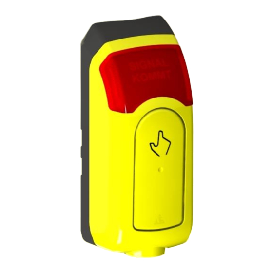
Page 4: Product Description
Product description This manual essentially describes installation and operation of the pedestrian signal requesting device for pedestrians and the visually impaired provided by Langmatz. Dimensions Fig. 1Fig. 2 Technical data General basicguide EK524 pedestrian signal requesting Designation device Nominal voltages... -
Page 5: Tactile Signalling Device
Tactile signalling device Designation Core Minimum Maximum Unit Neutral conductor, tactile signalling device Pedestrian crossing signal, tactile signalling device 1.2 U 0.8 U Voltage range Volts (max. 253 (min. 20 V) Input power Watts Nominal voltages 24 VDC / 40 VAC / 230 VAC Visual feedback Designation Core... -
Page 6: Block Diagram
Contact types NC / NO Background colour indicates core colour. Block diagram Fig. 3... -
Page 7: Scope Of Delivery
Scope of delivery 1 1x pedestrian signal requesting device of type “basicguide” with connection cable 2 2x fastening screws M6x25 (A2) 3 1x pole seal (flexible) 4 1x steel lighting-pole adaptor (A2) (protection against vandalism) for lighting poles with a diameter of 78 mm –... -
Page 8: Installation
(3) (for mounting). • Cut 2 M6 threads (3). • Drill 1 hole with a diameter of 14 mm (4) (for the cable duct). Langmatz recommends using a metal Fig. 6 drilling jig. Langmatz item no. 700663080. See also chapter 9 (Accessories) Opening the signal requesting device •... -
Page 9: Mounting The Bottom Part Of Signal Requesting Device
Mounting the bottom part of signal requesting device The bottom part (1) of the device is pre-assembled with the steel lighting- pole adaptor (protection against vandalism) (2) and pole seal (flexible) (3). Fig. 8 • Take off the plastic caps (captive) (2). •... -
Page 10: Installation Of Replacement Device (Hole Spacing 80 Mm)
Installation of replacement device (hole spacing 80 mm) If mounting holes (1) already exist (thread spacing 80 mm), a predetermined breaking point (2) can be opened in the bottom part (3) of the device. • Take off the plastic caps (captive) (4). •... -
Page 11: Aligning Crossing Symbol
Aligning crossing symbol The pedestrian signal requesting device is factory-fitted with a crossing symbol (1). If the specified direction of the crossing symbol does not match the direction required, proceed as follows: Fig. 12 • Insert the special key (1) behind the crossing symbol and press down. -
Page 12: Replacing Crossing Symbol
Replacing crossing symbol Description of the crossing symbols for the visually impaired DIN 32981 1 Crossing with additional request 2 Crossing only (factory-fitted) 3 Crossing with central island 4 Crossing with level crossing 5 Crossing in two directions A more detailed description of the symbols and their functions is specified in DIN 32981. -
Page 13: Set-Up And Function Test
Set-up and function test Vibration The vibrator (tactile signalling device) is connected to the corresponding crossing orientation signal of the traffic light system and can be operated with a voltage of 20 V DC to 253 V AC. The voltage range is set with a DIP switch. This ensures that the vibration can only be activated with the set voltage range. -
Page 14: Vibrator Push-Button
Operating voltages Switch 24 V 230 V 40 V 40 V position dim. dim. Fig. 19 Vibrator clock rate The vibrator clock rate can be set to the clock rate of the pedestrian Switch 1 Hz 2 Hz 4 Hz 6 Hz crossing signal with switch position 4 position... -
Page 15: Visual Feedback (Depending On Configuration)
Visual feedback (depending on configuration) DIP switch Visual feedback (1) The voltage range is set to 230 V and constant light on delivery. Fig. 22 Switch position 1 → on = flashing 2 Hz Switch 230 V 40 V 24 V →... -
Page 16: Speaker (Depending On Configuration)
Speaker (depending on configuration) The speaker is available for an external acoustic device. The function test depends on the type of acoustics used. Technical data of the speaker: 300-20000 Hz | 2 Watt | 8 Ohm Fig. 25 Note: If one or more of the above-mentioned settings do not work correctly, check the devices settings and connection configuration. -
Page 17: Accessories
Accessories Example illustration of the Designation Langmatz item no. product Drilling jig 700663080 Vandal guard 700663090 Available in various colours and with various pictograms on customer request... -
Page 18: Maintenance
The product meets the requirements of the following applicable harmonisation directives: 2014/30/EU Electromagnetic Compatibility (EMC) 2014/35/EU Low Voltage Directive (LVD) The following standards were complied with: EN 50293:2012 (EMC) EN 50556:2011 (LVD) DIN 32981:2018-06 The EU Declaration of Conformity for this product can be requested from Langmatz GmbH. -
Page 19: Material Defects
Material defects Langmatz shall assume liability for material defects in the product as per Section 434 BGB (German Civil Code) for 24 months, starting from the date on the purchase receipt. Within the scope of liability, all parts that become damaged due to manufacturing or material errors shall be replaced or repaired free of charge. - Page 20 12 524 0960 / 000 │ As of 18.11.2019 │ Original Operating Instructions...
Need help?
Do you have a question about the basicguide EK 524 and is the answer not in the manual?
Questions and answers