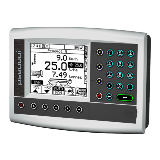
Summary of Contents for RDS Technology Apollo FYM
- Page 1 Apollo FYM Spreader Controller Calibration RDS Part No.: S/DC/500-10-746 Document Issue: 1.1 : 20.2.14 Software Issue: PS605-001rev09...
- Page 2 Use of the System is subject to the following disclaimer; So far as is legally permissible RDS Technology ("RDS"), or its distributors, shall not be liable, whatever the cause, for any increased costs, loss of profits, business, contracts, income,...
-
Page 3: Table Of Contents
APOLLO FYM - SPREADER CONTROLLER INTRODUCTION The "Setup" Screen page ......................... 5 Calibration on installation Calibration in normal use Data Entry..............................5 USER OPTIONS Set Time and Date ........................6 Adjust Screen Contrast and Brightness ..................6 Customise............................ 6 1.3.1 Nudge Step Size Select Language.......................... - Page 4 APOLLO FYM - SPREADER CONTROLLER PRODUCT SETUP Product Select..........................13 4.1.1 Product Name 4.1.2 Rate 4.1.3 ‘T’ Factor 4.1.4 Speed Range 4.1.5 T Store Point 4.1.6 Fast Empty Point SPREADER SETUP Working Width ..........................14 5.1.1 Set current Working Width Forward Speed Sensor........................
-
Page 5: Introduction
APOLLO FYM - SPREADER CONTROLLER Introduction The instrument must be calibrated before commencing normal operation. Many settings are made only on initial installation e.g. from the 'FACTORY CONFIG' screen. Other calibration settings may need to be altered on a regular basis according to the product being spread, spread width etc. -
Page 6: User Options
APOLLO FYM - SPREADER CONTROLLER User Options Configure basic instrument options. Set Time and Date 4. User Options 1. Time/Date If you need to change the time or date setting, position the cursor against the relevant line, key-in the new... -
Page 7: Nudge Step Size
APOLLO FYM - SPREADER CONTROLLER 1.3.1 Nudge Step Size The Nudge Step Size sets the % increase / decrease made when you adjust from the target rate in AUTO mode. Adjustable from 0 to 50%. Default = 5% Select Language 4. -
Page 8: Technician Config
APOLLO FYM - SPREADER CONTROLLER Technician Config The operator is unlikely to need access in normal use. Access to this menu can be restricted by changing the PIN number from within the menu. Enter the factory default PIN number 1234 to access the menu. -
Page 9: Loadcell Correction
APOLLO FYM - SPREADER CONTROLLER Loadcell Correction Figure 22 "Boom/Cutouts Inputs" page 2. Technician Config. 2. Loadcell Correction UK572-14.PCX Correction Span This is the amount that the T factor can be allowed to change by after each dynamic calibration test. If this figure is too large, floor speed correction may vary significantly, affecting the spread pattern and possibly overloading the driveline. -
Page 10: Print Calibration Data
APOLLO FYM - SPREADER CONTROLLER Print Calibration Data 2. Technician Config. 4. Print Cal data It is always a good idea to keep a record of calibration data either in the back of the manual, or as a printout. Connect the printer to the upper serial port. Ensure first that the port has been configured for a printer (section 4.5.1). -
Page 11: Factory Config
APOLLO FYM - SPREADER CONTROLLER Factory Config Machine Options 3. Factory Config. 1. Machine Options UK57223.PCX Spreader Config 3. Factory Config. 2. Spreader Config UK57223.PCX Shaft 1 and Shaft 2 are related to the spinner/beater sensors. The following calibration procedure applies regardless of the speed output being sensed e.g. -
Page 12: Feedback
APOLLO FYM - SPREADER CONTROLLER 3.4.1 Feedback The factor (pulses per revolution) is depending upon the number of pulses for 1 revolution of the rear floor roller. 3.4.2 Response The Response function sets the frequency at which the system adjusts the control valve when reacting to a change in forward speed. - Page 13 APOLLO FYM - SPREADER CONTROLLER Product Setup This menu enables access to configuring the system for different products, entering the product names and selecting the product to spread with. Product Select Figure 23 3. Product Select Main Page Option UK57223.PCX 4.1.1 Product Name...
- Page 14 APOLLO FYM - SPREADER CONTROLLER Spreader Setup Working Width 1. Spreader Setup 1. Working Width 5.1.1 Set current Working Width Using the numeric keypad, type in the current working width and use the ENTER button to confirm, UK572-02.PCX Forward Speed Sensor 5.2.1 Select Sensor Option...
- Page 15 APOLLO FYM - SPREADER CONTROLLER With the appropriate sensor option highlighted on the "SPEED FACTOR" page, press ENTER, then select "Auto Cal'. Press and then follow the screen instructions. Stop the vehicle when the second marker lines up with the pre-determined reference point on the vehicle and press to end the "Auto Cal"...
- Page 16 APOLLO FYM - SPREADER CONTROLLER 5.2.5 RDS ‘Satspeed’ Interface / NMEA VTG Input No calibration is necessary. Pre-Start See Pre-Start Setup guide in the Operators Manual, section 2.4. Alarms Setting the Alarm thresholds Press to select the "SETUP" menu. Select the "ALARMS SETUP" button at the base of the screen.
- Page 17 APOLLO FYM - SPREADER CONTROLLER Issue 1: 12/12/13 Original Issue Issue 1.1 20.2.14 Ref. CRQ5468...


Need help?
Do you have a question about the Apollo FYM and is the answer not in the manual?
Questions and answers