E-Mu 404 Owner's Manual
Digital audio system
Hide thumbs
Also See for 404:
- Owner's manual (112 pages) ,
- Getting started (64 pages) ,
- Tutorials manual (42 pages)
Table of Contents
Advertisement
Advertisement
Table of Contents

Related Manuals for E-Mu 404


Summary of Contents for E-Mu 404
- Page 1 O w n e r ’ s M a n u a l O w n e r ’ s M a n u a l...
- Page 2 E-MU 0404 Digital Audio System Owner’ s Manual © 2004 E-MU Systems All Rights Reserved Software Version: 2.00 E-MU World Headquarters E-MU Systems 1500 Green Hills Road Scotts Valley, CA USA 95066 Asia Pacific, Africa, Middle East Creative Technology Ltd.
-
Page 3: Table Of Contents
Setting Up the Digital Audio System ... 9 Notes for Installation ... 9 Safety First! ... 10 Connector Types ... 10 Installing the E-MU 0404 PCI Card ... 11 Install the Sync Card ... 12 Software Installation ... 13 Installing the E-MU 0404 Drivers ... 13 Windows XP, Windows XP x64, Windows Vista, Windows Vista x64 ... - Page 4 Importing and Exporting Core FX Presets and FX Insert Chains ... 48 FX Edit Screen... 49 User Preset Section ... 50 Core Effects and Effects Presets ... 51 WDM Recording and Playback Behavior ... 51 List of Core Effects... 52 E-MU Digital Audio System...
- Page 5 DSP Resource Usage ... 52 Core Effects Descriptions... 53 1-Band Para EQ ... 53 1-Band Shelf EQ ... 53 3-Band EQ ... 54 4-Band EQ ... 55 Auto-Wah ... 56 Chorus ... 57 Compressor ... 57 Basic Controls ... 58 Distortion ...
- Page 6 E-MU PowerFX Compatibility Chart ... 94 Rendering Audio with E-MU PowerFX ... 95 General Tips for Rendering using E-MU PowerFX ... 95 Tips for using Freeze Mode on Cubase LE ... 95 Using E-MU PowerFX with WaveLab and SoundForge ... 95 E-MU VST E-Wire ...
-
Page 7: 1- Introduction
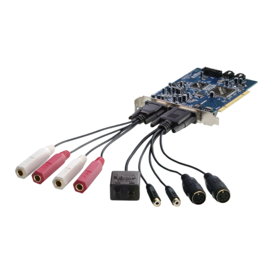
• Quick Start Guide The System Includes: The E-MU 0404 PCI Card provides 2 line level, unbalanced analog inputs, 2 line level, unbalanced analog outputs, plus MIDI input and output. This is a finely-tuned audio interface, using high performance 24-bit/192kHz A/D - D/A converters to deliver an unbelievable 111dB of dynamic range. -
Page 8: Optional Sync Daughter Card
Card eliminates timing problems caused by combining MTC with MIDI performance data. You’ll want to keep up with the latest software and options for your E-MU digital audio system. You can find all of this, plus other helpful information, at the E-MU Website: http://www.emu.com. -
Page 9: Installation
• Multiple Digital Audio System sound cards are currently not supported. Please read the following sections as they apply to your system as you install the E-MU 0404, paying special attention to the various warnings they include. E-MU Digital Audio System Setting Up the Digital Audio System Go there. -
Page 10: Safety First
• To avoid possible permanent damage to your hardware, make sure that all connections are made to the E-MU 0404 PCI card with the host computer’ s power off. Unplug the computer’ s power cable to make sure that the computer is not in sleep mode . -
Page 11: Installing The E-Mu 0404 Pci Card
Card as well, remove the bracket from two adjacent PCI slots. See figure 1 below. Figure 1 Align the E-MU 0404 PCI card with the slot and press gently but firmly down into the slot as shown in figure 2. -
Page 12: Install The Sync Card
Unwrap the Sync Card if you have one and get ready to install it. Connect the ribbon cable provided with the kit between the E-MU 0404 card and the Sync Daughter Card as shown in figure 3. The cable is keyed so it cannot be incorrectly inserted. -
Page 13: Software Installation
Software Installation Installing the E-MU 0404 Drivers The first time you restart your PC after installing the E-MU 0404 PCI card, you will need to install the PatchMix DSP software and E-MU 0404 PCI card drivers. Windows XP , Windows XP x64, Windows Vista, Windows Vista x64 The software is not compatible with other versions of Windows. - Page 14 2 - Installation Software Installation Creative Professional...
-
Page 15: Pci Card & Interfaces
3 - PCI Card & Interfaces The E-MU 0404 PCI Card The E-MU 0404 PCI card contains E-MU’s powerful E-DSP chip which leaves more power free on your CPU for additional software plug-ins and other tasks. Bit depth is controlled by your recording or audio application. The 0404 PCI card always sends and receives 24-bit audio. -
Page 16: Analog Input Connections
RCA phono jacks are the standard coaxial connectors used for S/PDIF (Sony/Philips Digital InterFace) connections. A single jack carries two channels of digital audio. The E-MU 0404 receives digital audio data with word lengths of up to 24-bits. Data is always transmitted at 24-bits. - Page 17 AUDITION TRIGGER MODE MIDI Sound Module MIDI Sound Module 3 - PCI Card & Interfaces The E-MU 0404 PCI Card Important: When using any type of digital I/O such as S/PDIF , you MUST sample sync the two devices or clicks and pops in the audio will result.
-
Page 18: The Sync Daughter Card Option
3 - PCI Card & Interfaces The Sync Daughter Card Option The Sync Daughter Card Option The Sync Daughter card option adds word clock in and out, SMPTE (LTC) in and out and an additional MIDI output for transmitting MIDI Time Code (MTC). MIDI Time Code is a special rendering of SMPTE that can be transmitted over MIDI cables. -
Page 19: The Patchmix Dsp Mixer
It’s easy and it works…beautifully! To Invoke the PatchMix DSP Mixer Left-click once on the E-MU icon DSP mixer window appears. Overview of the Mixer Physical Input Strips... -
Page 20: Mixer Window
“TV” which shows parameters for the currently selected effect and the input/output patchbay. It also shows the session’ s current sample rate and whether the Digital Audio System is set to internal or external clock. Mixer Strips This section is located to the left of the Main Section and shows all the currently instantiated mixer strips. -
Page 21: E-Mu Icon In The Windows Taskbar
E-MU Icon in the Windows Taskbar Right-clicking on the E-MU icon in the Windows taskbar calls up the following window. Right-Click Here The Toolbar Save Session Session Open Session Settings New Session Calls up the “New Session” dialog box. Open Session Calls up the standard “Open”... -
Page 22: The Session
4 - The PatchMix DSP Mixer The Session The Session The current state of the PatchMix DSP mixer (fader settings, effects routings…every- thing!) can be saved as a Session. Whenever you create or modify a mixer setup, all you have to do is Save it to be able to recall it at a later time. Before you begin using PatchMix DSP, you need to set it up to be compatible with the other software applications you may be running. -
Page 23: Open Session
You can create your own templates by simply copying or saving sessions into the “Session Templates” folder (Program Files\Creative Professional\Digital Audio System\E-MU PatchMix DSP\Session Templates). The “Session Path” allows you to choose the destination for your Session. The default location is in the “My Sessions” folder within the “My Documents” folder. -
Page 24: Session Settings
4 - The PatchMix DSP Mixer The Session Session Settings System Settings Pressing the Session Settings button on the toolbar brings up the System Settings window shown below. Click the tabs to select System or I/O options. The System Settings include the following choices: •... -
Page 25: I/O Settings
S/PDIF. • PCI Card S/PDIF Input • S/PDIF Output Format E-MU Digital Audio System “To Set the Input Levels of a Strip” Selects between coaxial or optical S/PDIF input. S/PDIF out is always transmitted on both the coaxial and optical outputs. -
Page 26: Input Mixer Strips
4 - The PatchMix DSP Mixer Input Mixer Strips Input Mixer Strips PatchMix DSP Line Input Mixer Strips are mono. The WAVE and S/PDIF strips are stereo. Each input mixer strip can be divided into four basic sections. • Insert Section Effects, EQ, External/Host Sends and Returns can be inserted into the signal path. -
Page 27: Mixer Strip Creation
WAVE 3/4 - Additional WDM channels Select Pre-Fader Aux Sends or leave the box unchecked for Post-Fader Aux Sends. Click OK to create a new strip or Cancel to cancel the operation. E-MU Digital Audio System See Overview of the Mixer Physical... -
Page 28: Multichannel Wave Files
4 - The PatchMix DSP Mixer Mixer Strip Creation To Delete a Mixer Strip: Click the top of the mixer strip you wish to delete. A red border appears around the strip, indicating that it is selected. Click on the Delete Mixer Strip button or right-click and choose Delete, or use the Delete key on the PC keyboard. -
Page 29: Insert Section
Note: The Physical Output & Input option is “grayed-out” when using the default Session Reason: The 0404 Digital Audio System has only 4 physical inputs and 4 physical outputs. The Send/Return option is grayed-out because all the physical I/O resources available for send/return have been used in this Session. -
Page 30: The Insert Menu
4 - The PatchMix DSP Mixer Mixer Strip Creation The Insert Menu Right-Clicking over the insert section brings up a pop-up selection box containing various insert options to help you control and manage your inserts. To Add a Send Insert: This type of insert send splits the signal at the insert point and sends it out to the selected destination. -
Page 31: Asio Direct Monitor Send/Return
In this case, set the PatchMix DSP stereo pan controls hard left and right, mono pan controls to center, and the fader to 0dB. E-MU Digital Audio System Input To Physical Output... -
Page 32: Meter Inserts
4 - The PatchMix DSP Mixer Mixer Strip Creation To Add an ASIO Direct Monitor Send/Return: Right-Click over the Insert section. A pop-up dialog box appears. Select “Insert ASIO Direct Monitor” from the list of options. The following dialog box appears. Choose one of the Send Outputs. -
Page 33: To Set The Input Levels Of A Strip
Comparison of -10dBV & +4dBu Signal Levels Consumer (unbalanced) + 6 dBV Clipping --> Headroom + 2 dBV -10 dBV 0 dBV = 1V RMS E-MU Digital Audio System Professional (balanced) +20 dBu <-- Clipping Headroom +8 dBu +4 dBu -8 dBu 0dBu = .777V RMS... -
Page 34: Making The Best Possible Recording
12-bit or 16-bit converters of the past. Even so, to get the best performance possible, you'll need to follow a few basic guidelines. First, whenever you input an analog signal to the Digital Audio System, make sure that you're feeding the A-D converters with an optimum signal level. The quality of a digital recording is directly related to the signal level you feed into the A-D converters. -
Page 35: Trim Pot Insert
(analogous to white light in the visible spectrum). Pink noise provides equal power distribution per octave. (White noise has more power in the higher octaves.) Pink noise and white noise are useful as wideband sound sources. E-MU Digital Audio System Gain/Attenuation Phase Invert Meters... -
Page 36: Managing Your Inserts
4 - The PatchMix DSP Mixer Mixer Strip Creation Managing Your Inserts To Delete Effects from an Insert: Right-Click over the Insert Effect you wish to delete. A yellow line around the insert location indicates that it is selected. A pop-up dialog box appears. Select Delete Insert to remove the selected insert or select Delete All Inserts to remove all inserts. -
Page 37: Aux Section
These two mixes can be routed anywhere, such as to a physical output or an ASIO pair. You could route one of the Aux buses to the Monitor out to create a monitor mix while sending the main mix off to your audio recording software. E-MU Digital Audio System Sidechain Diagram (Post-Fader Aux Sends) -
Page 38: Pre Or Post Fader Aux Sends
4 - The PatchMix DSP Mixer Mixer Strip Creation Pre or Post Fader Aux Sends When you create a New Mixer Strip you have the option to place both Aux Sends after the channel volume fader and mute control or you can place them before the fader and mute. -
Page 39: Level, Pan, Solo & Mute Controls
Level Control Mute & Solo Buttons Scribble Strip E-MU Digital Audio System The Pan control comes before the Level Control and Aux Sends in the signal flow. On stereo strips we use an unconventional pan section with two pan pots – one for the left part of the signal and one for the right part of the signal. -
Page 40: Main Section
4 - The PatchMix DSP Mixer Main Section Main Section Physical/Host Select Buttons “TV” Screen Master Aux Send Amounts Main Insert Section Output Fader & Meters The main section contains all controls for controlling the main mix elements as well as a “TV screen”... -
Page 41: Tv Screen & Selectors
Send is going and where the Return is coming from. The buttons at the top of the display allow you to bypass or solo the Send/Return insert. E-MU Digital Audio System for detailed information about the individual Effect Location Effect Bypass &... -
Page 42: Input
4 - The PatchMix DSP Mixer Main Section Input Selecting the Input display view shows a graphic representation of the PatchMix DSP Mixer inputs. This screen is only a display unlike the Effects and Outputs screen, which allow you to make routing changes. Input routing changes are made by adding mixer strips. -
Page 43: Auxiliary Effects & Returns
48kHz clock until the proper external clock is restored. The “LOCKED” LED will be off and the two units are NOT synchronized. Always check the “LOCKED” LED when using an external clock source. E-MU Digital Audio System Input Input... -
Page 44: Output Section
4 - The PatchMix DSP Mixer Main Section Output Section Main Insert Section Output Level Main Inserts The main inserts allow you to apply effects to the main stereo signal coming out of the mixer (both mains and monitor). You might want to apply EQ or a compressor here. These inserts work just like the other effect locations—just drag and drop effects from the palette or right-click and add Sends, Sends/Returns. -
Page 45: Effects
You can also add, delete, or modify Effects Chains and the folders that contain them. For more information on Effects Chains, see “FX Insert Chains” on page New Folder Icon Import/Export FX E-MU Digital Audio System Effect Categories Core Effects Multi-Effects Distortion Lo-fi Drums & Percussion... -
Page 46: Fx Insert Chains
5 - Effects The Effects Palette To Select an Effect Click the FX button to bring up the Effects Palette. The effect palette contains numerous folders containing effects presets. Click on any folder to open it. Select the effect you wish to use by clicking on it with the left mouse button and while continuing to hold the mouse button, drag the effect into the desired location on the PatchMix DSP mixer screen and release the mouse button. -
Page 47: The Order Of Effects
When operating at 88kHz 96kHz, 176kHz and 192kHz sample rates, the effect processors are completely disabled. However, the Inserts, Send/Returns, Meters, Trim Controls, Test Tones and ASIO Direct Monitoring ARE fully functional. E-MU Digital Audio System Input If you want Effects... -
Page 48: Importing And Exporting Core Fx Presets And Fx Insert Chains
You can share presets with your friends or download new presets from the Internet. To Import Core FX Presets This option imports complete folders of Core FX presets into the E-MU PatchMix DSP folder (normally located here: “C:\Program Files\Creative Professional\E-MU PatchMix DSP\Core Effects”). -
Page 49: Fx Edit Screen
This feature is very useful when adjusting the effect parameters. Method #1 Click on the Insert (in the Insert section). Click the Solo button in the TV display. E-MU Digital Audio System Note: Effects have to be placed into an insert location before you can program them. -
Page 50: User Preset Section
5 - Effects FX Edit Screen Method #2 Right-click over the Insert Effect you want to Solo (in the Insert section). A pop-up menu appears. Select “Solo Insert” from the list of options. The other Insert Effect names in the strip will “gray-out”... -
Page 51: Core Effects And Effects Presets
Core Effects and Effects Presets The Core Effects cannot be removed or copied. Effect presets (stored in “C:\Program Files\Creative Professional\Digital Audio System\E-MU PatchMix DSP\Effect Presets”) can be copied, e-mailed or shared like any other computer file. Hint: Open with “NotePad” or other word processor to view and edit the name and parameters. -
Page 52: List Of Core Effects
5 - Effects List of Core Effects List of Core Effects Stereo Reverb Rotary Lite Reverb Phase Shi fter RFX Compressor Frequency Shifter Compressor Auto-Wah Reshaper Vocal Morpher Gate 1-Band Para EQ Leveling Amp 1-Band Shelf EQ Chorus 3-Band EQ Flanger 4-Band EQ Distortion... -
Page 53: Core Effects Descriptions
Corner Frequency Sets the frequency where the signal begins getting cut or boosted with the Gain control. Range: -15dB to +15dB E-MU Digital Audio System This single band parametric equalizer is useful when you just want to boost or cut a single range of frequencies. -
Page 54: 3-Band Eq
5 - Effects Core Effects Descriptions 3-Band EQ This versatile equalizer provides two shelving filters at the high and low ends of the frequency range and a fully parametric band in the center. Up to ±24 dB of boost or cut is provided for each band. -
Page 55: 4-Band Eq
Sets the amount of cut (-) or boost (+) of the low frequency shelf. Range: -24dB to +24dB Low Corner Freq. Sets the frequency where the signal begins getting cut or boosted with the Low Gain control. Range: 50Hz to 800Hz E-MU Digital Audio System page 54. Mid 2-Band High-Shelf Corner... -
Page 56: Auto-Wah
5 - Effects Core Effects Descriptions Auto-Wah This effect creates the sound of a guitar wah-wah pedal. The “Wah” filter sweep is automatically triggered from the amplitude envelope of the input sound. Auto-wah works well with percussive sounds such as guitar or bass. The Auto-Wah is a bandpass filter whose frequency can be swept up or down by an envelope follower, which extracts the volume contour of the input signal. -
Page 57: Chorus
This level is called the Threshold, which just happens to be the most important control on the compressor. Delay Level Control Threshold Ratio Attack Release E-MU Digital Audio System Post Gain 5 - Effects Core Effects Descriptions... -
Page 58: Basic Controls
5 - Effects Core Effects Descriptions Basic Controls The three main controls of a compressor are the Ratio control, the Threshold control and the Gain control. If the signal level falls below the Threshold, no processing will take place. Signals exceeding the Threshold will have gain reduction applied as set by the ratio control. -
Page 59: Distortion
Post EQ Center Freq. Sets the frequency of the output bandpass filter. Range: 80Hz to 24kHz Post EQ Bandwidth Sets the width of the output bandpass filter. Range: 80Hz to 24kHz E-MU Digital Audio System Bandpass Filter Distortion EQ BW Gain... -
Page 60: Flanger
5 - Effects Core Effects Descriptions Flanger A flanger is a very short delay line whose output is mixed back together with the original sound. Mixing the original and delayed signals results in multiple frequency cancella- tions known as a comb filter. Since the flanger is a type of filter, it works best with harmonically rich sounds. -
Page 61: Freq Shifter
Range: .01Hz to 24kHz Left Direction Sets pitch shift up or down for the left channel. Right Direction Sets pitch shift up or down for the right channel. E-MU Digital Audio System Frequency Shifted (100 Hz) 1200 1500 1100... -
Page 62: Leveling Amp
5 - Effects Core Effects Descriptions Leveling Amp The first compressors developed in the 1950’s were based on a slow-acting optical gain cells which were able to control the signal level in a very subtle and musical way. This effect is a digital recreation of the leveling amps of yesteryear. The leveling amp uses a large amount of “lookahead delay”... -
Page 63: Lite Reverb
Sets the volume of the initial wall reflections. Range: 0% to 100% Reverberance Sets the amount of scattering of the early reflections and the reverberation cloud. Range: 0% to 100% E-MU Digital Audio System Core Effects Descriptions Time 5 - Effects... -
Page 64: Mono Delays - 100, 250, 500, 750, 1500, 3000
5 - Effects Core Effects Descriptions Mono Delays - 100, 250, 500, 750, 1500, 3000 A delay line makes a copy of the incoming audio, holds it in memory, then plays it back after a predetermined time. The delay number refers to the maximum delay time that can be produced by the delay line. -
Page 65: Phase Shifter
Selects a Sine or Triangle wave for the LFO LFO L/R Phase Controls the stereo width by adjusting the phase difference between the left and right sweeps. Range: -180° to +180° E-MU Digital Audio System 5 - Effects Core Effects Descriptions... -
Page 66: Rotary
5 - Effects Core Effects Descriptions Rotary This is a simulation of a rotating speaker used on organs. The rotating speaker was invented to give static organ tones a pipe organ type of animation, but this distinctive sound became a legend in its own right. Spinning a sound around the room creates a doppler pitch shift along with many other complex and musically pleasing sonic effects. -
Page 67: Stereo Delays - 100, 250, 550, 750, 1500
Sets the amount of delayed signal that will be recirculated through the delay line. Range: 0% to 100% High Freq. Rolloff Damps high frequencies in the feedback path. Range: 0% to 100% E-MU Digital Audio System Feedback R Delay Time... -
Page 68: Stereo Reverb
5 - Effects Core Effects Descriptions Stereo Reverb Reverberation is a simulation of a natural space such as a room or hall. The stereo reverb algorithm is designed to simulate various halls, rooms and reverberation plates. Decay time defines the time it takes for the reflected sound from the room to decay or die away. -
Page 69: Vocal Morpher
LFO Rate Controls how fast the phonemes morph back and forth. Range: .01Hz to 10Hz LFO Waveform Selects the waveform for the morph: Sinusoid, Triangle, Sawtooth E-MU Digital Audio System Phoneme B Phoneme A 5 - Effects Core Effects Descriptions... -
Page 70: Gate
5 - Effects Core Effects Descriptions Gate This stereo noise gate is useful both for background noise reduction applications and also for special effects. The gate uses an envelope follower and threshold detector to turn on its output when the input signal is above the turn-on threshold, and shut down its output when the signal falls below the shut-off threshold. -
Page 71: Parameters
Gate turns on. However, this is actually implemented by adding a 1 millisecond delay to the signal through the gate. For appli- cations where this additional 1 millisecond latency is a problem, the Lookahead can be turned Off. E-MU Digital Audio System... -
Page 72: Level Meter
5 - Effects Core Effects Descriptions Level Meter This meter represents the input signal level in dB, and is in fact the output of the Gate's envelope follower. Since the envelope follower is driven by the greater of the left or right channel, this monophonic meter represents the greater of the two input signals. -
Page 73: Reshaper
Release Level where it remains until the another input transient triggers the next Attack phase. 0 dB Threshold Release Threshold Original Waveform 0 dB Sustain Level Release Level Reshaped Waveform E-MU Digital Audio System Attack Decay Time Time 5 - Effects Core Effects Descriptions Hold Release Time Time... - Page 74 5 - Effects Core Effects Descriptions Attack, Decay and Release times are all adjustable, and the shape of each of these segments is selectable between exponential, linear, or logarithmic. An additional Hold Time can be used to extend the Sustain phase past the point where the signal has passed the Release Threshold.
- Page 75 Release Curve This parameter selects gain curves exactly as for the Attack Curve parameter, except that the selected curves apply to both the Decay and Release phases of the ADSR. E-MU Digital Audio System 5 - Effects Core Effects Descriptions...
-
Page 76: Multimode Eq
5 - Effects Core Effects Descriptions Multimode EQ The Multimode EQ is a flexible stereo filter that is capable of implementing a range of powerful filter topologies. It is useful both for utility EQ applications and also for special effects. The Multimode EQ is built from an array of filter sections that can be configured to support: •... -
Page 77: Parameters
In this mode, the Highpass filter can have up to a 48dB/octave rolloff slope. The Highpass Rolloff, Highpass Frequency and Highpass Resonance parameters are available for editing the filter response. E-MU Digital Audio System 5 - Effects Core Effects Descriptions... -
Page 78: Highpass -> Lowpass
5 - Effects Core Effects Descriptions Highpass -> Lowpass In this mode, the Lowpass and Highpass filters are connected in series and both sets of Lowpass and Highpass parameters are exposed and independently editable to create the overall filter response. The maximum rolloff slope of each filter is limited to 24dB/ octave in this mode. -
Page 79: Band Pass
Lowpass and Highpass filters. In this mode the rolloff slope on the high and low sides of the cut-band is symmetrical and is limited to a maximum of 24dB/octave.The Resonance is also common to both filter sections . E-MU Digital Audio System Core Effects Descriptions Resonance = 0... -
Page 80: Rfx Compressor
5 - Effects Core Effects Descriptions RFX Compressor The RFX Compressor is a full-featured stereo compressor effect which features the standard parameters available on most compressors as well as a collection of additional advanced parameters that are useful for more sophisticated applications and special effects: •... -
Page 81: Parameters
When the Auto-release parameter is in its signal-dependent settings, the Release time shown represents the shortest possible release time. In Auto-release modes the displayed Release time will be automatically extended depending on the dynamics of the input signal. E-MU Digital Audio System Threshold: -30dB -30dB -80dB... -
Page 82: Gain
5 - Effects Core Effects Descriptions Gain Sets the compressor's output gain in dB, from +60dB boost to-60dB cut. This control follows all of the other elements in the compressor's signal path, so positive gain boost can be used to make up for the gain reduction normally applied to signals above the compression threshold. - Page 83 Auto Makeup Gain parameter. Thus signal levels below the Threshold increase as the Soft Knee depth and/or Ratio is increased (but see the Gate parameter, below.) E-MU Digital Audio System Knee Threshold -10dB...
-
Page 84: Gate
5 - Effects Core Effects Descriptions Gate This parameter enables automatic gain reduction on signals that fall from 1 to 120dB below the Threshold point (or Soft Knee threshold, if enabled.) This can act effectively as a “noise gate” on low-level signals that have been boosted by the action of the Gain or Soft Knee parameters. -
Page 85: Auto-Release
Ratio settings than at lower ones. Uncompressed Waveform Short Release Program-Dependent Release With Auto-release turned on, the release time becomes longer after an extended period of compression. E-MU Digital Audio System Longer Release 5 - Effects Core Effects Descriptions... -
Page 86: Max Compression
5 - Effects Core Effects Descriptions Max Compression This parameter is used to limit the amount of gain reduction that the compressor can apply. The limit is set as a maximum number of dB of gain reduction, from 3dB to UNLIMITED. -
Page 87: Input Mode
Attack and Release times — use a liberal amount of Compression Lookahead to keep the background from masking the beginning of foreground sounds. Creating a Ducker Ducker Background Signal Gain Pan -90 (L) Cell Stereo Strip Foreground Signal Sidechain Pan +90 (R) E-MU Digital Audio System... -
Page 88: Example Settings
5 - Effects Core Effects Descriptions Example Settings Here we have provided a few examples to show the varied uses of this useful tool. Bear in mind that these examples are simply starting points and that you will undoubtedly need to fine tune the parameters to fit the program material and to suit your own taste. Increase Drum Punch: Adjust the Threshold control to control the amount of compression. - Page 89 • Ratio: -1:1 (Neg. Compression enabled) • Attack: Instantaneous • Release: 200 msec • Gain: +19dB • Soft Knee: Off • Gate: Off • Comp. Lookahead: -24 msec • Auto-release: Off • Max. Compression: Unlimited E-MU Digital Audio System 5 - Effects Core Effects Descriptions...
-
Page 90: Multimode Eq Settings
5 - Effects Core Effects Descriptions Creating a De-esser: A de-esser reduces the sibilance or “sss” sound in a vocal part. The sidechain feature of the RFX Compressor makes it possible to create a effective de-esser using the compressor and the Multimode EQ. The Wet/Dry Mix on each effect should be set to 100% The idea is to boost the high frequency content going to the sidechain (R input) so that the compressor will turn down the volume in the presence of sibilance. -
Page 91: E-Mu Powerfx
The hardware-accelerated effects of the E-MU Digital Audio System can also be used as VST inserts in Cubase LE. E-MU PowerFX allow you to use PatchMix DSP effects from within Cubase, Sonar, or other host application with minimal load on your CPU. - Page 92 Setup E-MU PowerFX Make sure the Insert Enable button Power FX is on. The blue “Signal Present” indicators will be illuminated if E-MU PowerFX is properly patched into a signal path. Drag the desired effects from the Effects Palette to the center Insert strip.
-
Page 93: Automating E-Mu Powerfx
• If DSP resources ARE available, but no Hardware I/O Paths are available, the plug-in will run in soft pass-through mode. • If the sample rate is changed in the middle of a PowerFX session, E-MU PowerFX plug-ins will be bypassed, since the hardware effects cannot operate at 96kHz or 192kHz. -
Page 94: E-Mu Powerfx Compatibility Chart
5 - Effects E-MU PowerFX E-MU PowerFX Compatibility Chart Application Name Compatible? Steinberg Cubase VST 5.1 Steinberg Cubase SX 1 Steinberg Cubase SX 2 Steinberg Cubase LE Steinberg Cubase SL Steinberg WaveLab 4 Steinberg WaveLab Lite (ver 4) Steinberg WaveLab 5... -
Page 95: Rendering Audio With E-Mu Powerfx
Stuttering in the audio can occur when rendering with SoundForge or any version of Steinberg WaveLab. This problem is caused by discontinuities in the first few audio buffers as they are fed by WaveLab to E-MU PowerFX. The problem can be eliminated by following these guidelines. -
Page 96: E-Mu Vst E-Wire
Send to Strip Return to VST PatchMix DSP for E-Wire Note: It’ s easier to use E-MU PowerFX instead of E-Wire if you just want to use the hardware effects. (E-Wire was the precursor to E-MU PowerFX.) However, E-Wire can be... -
Page 97: E-Delay Compensator
E-Wire on any other audio tracks. That’s it. E-Delay Compensator As audio is transferred back and forth between the VST host application and the E-MU sound hardware, a delay in the audio stream is incurred. Normally this delay is compen- sated for automatically by the host application, but not all VST host applications support this automatic compensation. -
Page 98: E-Delay Compensator Use
5 - Effects E-MU VST E-Wire Currently automatic delay compensation is supported by the Steinberg 2.0 family (Nuendo 2.x, Cubase SX 2.0, Cubase LE 2.0,), Magix Samplitude 7.x, and Sonar (using the Cakewalk VST adapter 4.4.1), but not by Steinberg Cubase VST 5.1 and Cubasis. -
Page 99: Grouping Tracks
E-Delay Compensator on the output of the group or bus. • E-MU Digital Audio System and PatchMix DSP must be installed. • E-Wire is compatible with Cubase SX/SL/LE, Cubase VST, Wavelab, and Cakewalk Sonar (via DirectX-VST adapter) among others. - Page 100 5 - Effects E-MU VST E-Wire Creative Professional...
-
Page 101: Appendix
PatchMix DSP mixer becomes visible. Pressing the SMPTE button brings up the SMPTE window. Start Striping Current Time Start Time SMPTE Frame SMPTE Status/ Rate Settings Error Indicators E-MU Digital Audio System SMPTE Flywheel Mode: • Off • Continuous • Fixed •1-time Jam Stop Output... -
Page 102: Smpte Modes Of Operation
6 - Appendix Sync Daughter Card Supplement Sets the transmitted frame rate when striping SMPTE. Mode (fps) Edit this field to set the start time in hours:minutes:seconds:frames for SMPTE Striping striping SMPTE. Initiates SMPTE Time Code generation at the SMPTE output beginning at Stripe Button the time set in the striping display. -
Page 103: Stripe Mode
The four frame rates are all straightforward except 30 drop-frame. The 30 df rate came about because the US color video frame rate is actually 29.97 frames/sec instead of 30 frames/sec. This adds up to an error of 108 frames each hour relative to “wall clock” E-MU Digital Audio System Seconds Minutes... -
Page 104: Why Use Smpte
6 - Appendix SMPTE Background time! (A one hour program would actually be 59 minutes and 56.4 seconds long.) Drop frame was designed to correct this time difference. In 30 Drop Frame, every minute except 00-10-20-30-40-50 have the first two frames, 00 and 01, “dropped”, hence the name drop-frame. -
Page 105: Duplicating Smpte Time Code
MTC its own MIDI output port on the Sync Daughter Card. This ensures that the timing information will not be affected by other MIDI data on the line. E-MU Digital Audio System 6 - Appendix MIDI Time Code (MTC) -
Page 106: Word Clock In/Out
The E-MU 0404 PCI card can be externally clocked from the S/PDIF input (either optical or electrical) or from the Sync Daughter card (if installed). In a digital studio, all digital devices in the system should run off the same master Word Clock. -
Page 107: Digital Mixer
Word Clock Termination ON This diagram shows the proper way to connect word clock if you don’t have a multi-output word clock generator. The last device in a Word Clock chain should have Termination ON. E-MU Digital Audio System Digital Mixer Word Clock... -
Page 108: Getting In Sync
In the second example a second S/PDIF cable is used to supply “embedded word clock”. The external device MUST be set to receive external clock via S/PDIF or the units will not be synchronized. The E-MU Digital Audio System is the Master and the external A/D is the Slave. -
Page 109: Useful Information
This simple adapter cable allows you to receive AES/EBU digital audio via the S/PDIF input on the E-MU 0404 PCI card. This cable may also work to connect S/PDIF out from the 0404 digital breakout cable to the AES/EBU input of other digital equipment. -
Page 110: Technical Specifications
6 - Appendix Technical Specifications Technical Specifications GENERAL 44.1 kHz. 48 kHz, 88.2 kHz, 96 kHz, 176.4 kHz and 192kHz Sample Rates derived from internal crystals. (No sample rate conversion is performed.) Externally supplied clock from S/PDIF . (or word clock with optional Sync Card) 16-bit or 24-bit (depending on the setting of your recording Bit Depth or audio application) -
Page 111: Dimensions And Weight
Input Impedance: Dimensions & Weight 0404 PCI Card 0.25lb / 0.10kg Weight: L: 156mm H: 107mm Dimensions: Sync Daughter Card 0.25lb / 0.10kg Weight: L: 5.04" / 128mm Dimensions: E-MU Digital Audio System switchable) 795ps 6 - Appendix Technical Specifications... -
Page 112: Internet References
...http://www.synthzone.com ASIO, Cubase & Digital Audio...http://www.steinberg.net ASIO, Cubase & Digital Audio...http://www.steinbergusers.com/cubasele/ Cubase Users Group ...http://www.groups.yahoo.com/group/ Forums Unofficial E-MU Forum ...http://www.productionforums.com/emu/ E-MU Newsgroup (Yahoo) ... Forum...http://www.kvr-vst.com/forum/search.php Driver Heaven Forum ...http://www.driverheaven.net/search.php?s MIDI Addict Forum... Home Recording Forum...http://homerecording.com/bbs/ Sound-On-Sound Forum...http://sound-on-sound2.infopop.net/2/ Studio-Central Cafe Forum...http://studio-central.com/phpbb/search.php Sound Card Benchmarking ...http://audio.rightmark.org... -
Page 113: Declaration Of Conformity
The supplied interface cables must be used with the equipment in order to comply with the limits for a digital device pursuant to Subpart B of Part 15 of FCC Rules. E-MU Digital Audio System 6 - Appendix Internet References... -
Page 114: Compliance Information
6 - Appendix Internet References Compliance Information United States Compliance Information FCC Part 15 Subpart B Class B using: CISPR 22(1997) Class B ANSI C63.4(1992) method FCC Site No.90479 Canada Compliance Information ICES-0003 Class B using: CISPR 22(1997) Class B ANSI C63.4(1992) method Industry of Canada File No.IC 3171-B European Union Compliance Information... -
Page 115: Index
Band Cut Filter 79 Band Pass Filter 79 Block Diagram, mixer 20 Bypass all inserts 50 effect insert 49 send/return insert 41 E-MU Digital Audio System Category create new preset 47 delete effects 47 rename effects 47 CDs, playing 27 Chorus 57 using freq. - Page 116 30 bypass 36 delete 36 menu 30 meter 33 mixer strip 29 solo 36 types 29 Installing E-MU 0404 PCI card 11 sync cables 18 sync daughter card 12 Interface MIDI 18 S/PDIF 16 SMPTE 18 Creative Professional...
- Page 117 34 main output 44 setting input levels using 33 MIDI connections 17 thru 17 time code 105 E-MU Digital Audio System Mixer block diagram 20 overview 19 strip 26 aux send 37 delete 28 fader 39...
- Page 118 30 Send/Return Levels 40 Send/Return, greyed out or unavailable 29 Session 22 creating new 22 path 23 templates 23 Setting Up, E-MU Digital Audio System 9 Settings I/O 25 S/PDIF 25 sample rate 24 system 24 Sibilance, reducing 90...
- Page 119 WAVE Strips 27 multichannel 27 recording & playback behavior 51 WDM/KS 28 Weight, of card 111 Wet/Dry Mix, effects 49 Windows Media Player 27 Windows Taskbar, E-MU icon 21 Word Clock In/Out 18 Zero-Latency Monitoring 31 E-MU Digital Audio System Index...
- Page 120 Index Creative Professional...
Need help?
Do you have a question about the 404 and is the answer not in the manual?
Questions and answers