
Summary of Contents for Eding CNC UIO-10
- Page 1 User Manual UIO-10 DRAFT – WORK in PROGRESS Please note, the current IO-10 Setup is in Beta modus. There are several things we want to improve. However, we’re always happy to get some feedback.
- Page 2 Document History Version Date Author Comment © Copyright EdingCNC B.V. All rights reserved. Reproduction in whole or in part prohibited without the prior written consent of the copyright owner.
- Page 3 Table of Contents Connecting the board ........................... 4 UIO-10 Hardware conncetions ......................6 On/Off switch ............................6 Toggle Switch ............................6 Rotary Switch ............................6 Handwheel ..............................6...
-
Page 4: Connecting The Board
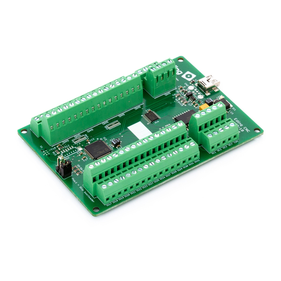
This manual describes how to use the EdingCNC UIO-10. 1. Connecting the board After the board has been connected with a USB cable with Mini USB-B connection start the software. <TODO: How is board reported under windows???) The software should detect it, this is shown in the message window. - Page 5 2x 5V 2x 3.3V IO16 Mini IO17 IO32 LED1/LED3 Toggle = Bootloader modus, after about 10 seconds continues. JP1 = Skip bootloader...
-
Page 6: Toggle Switch
Handwheel Up to 3 handwheels can be connected to the UIO-10. However it’s important to note that only on 6 inputs are able to connect a handwheel on. Connecting on other inputs can damage the UIO-10. - Page 7 Setup the software: Note, make sure when configuring your UIO-10 that your controller card is also connected.
- Page 8 Test connection: Connected switch, for example IO17. Now click on ‘6) Testmode on/off’. And observe that it will show when the input is active by turning green. To continue, deselect ‘6) Testmode on/off’.
- Page 9 Adding switch function: Let say we want to add a function to this switch: When the switch is turned ON it should switch on the spindle, and when you switch it OFF the spindle should stop. You do this in several steps: 1.
- Page 10 Momentary switch If you connect a button switch this will work the same, you can either have something be active as long as you press a button. For example, jogging. You can select ‘Start Jog Plus X’ as action #1 (the press down action), and select ‘Stop Jog’...
- Page 11 ‘selector switch’. For each input you select an extra action will be shown on the right side of the screen. Handwheel Up to 3 handwheels can be connected to the UIO-10. Not all inputs of the board can be used for handwheels.
Need help?
Do you have a question about the UIO-10 and is the answer not in the manual?
Questions and answers