
Summary of Contents for AKT HS-S86E
- Page 1 HS-S86E EtherCAT Easy Servo User Manual EN Version: V1.0 (Based on CH Version:V1.2) AKT Automation Technology Co., Ltd. www.aktmotor.com...
-
Page 2: Table Of Contents
HS-S86E User Manual Contents Foreword ......................1 1 Overview ....................... 2 1.1 Product Description ....................2 1.2 Feature ........................2 1.3 Application Field ......................2 1.4 Product Naming Rules ....................2 2 Performance Indicators .................. 3 2.1 EtherCAT Characteristic ..................... 3 2.2 Electrical Characteristics ..................... - Page 3 8.1 Object Dictionary List ....................36 8.2 Drive Related Parameters Description ................. 49 9 Alarm Exclusion ..................56 9.1 Drive Error ......................56 9.2 EtherCAT Communication Error ................56 Appendix 1: Getting Started with HS-S86E Drive Quick Configuration ... 58...
-
Page 4: Foreword
HS-S86E User Manual Foreword Thank you for using our EtherCAT hybrid servo drive. Before using this product, be sure to read the manual to learn the necessary safety information, precautions, and operating methods. Incorrect handling may lead to extremely serious consequences. -
Page 5: Overview
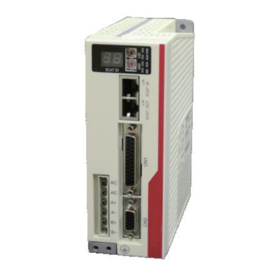
1 Overview 1.1 Product Description HS-S86E EtherCAT hybrid servo drive adds EtherCAT bus communication to the digital hybrid servo drive and supports intelligent motion control. It supports the COE protocol and supports the market's mainstream master controller as a standard EtherCAT slave drive unit. -
Page 6: Performance Indicators
HS-S86E User Manual 2 Performance Indicators 2.1 EtherCAT Characteristic Parameter HS-S86E Link layer 100BASE-TX Ethernet Communication RJ45 Standard network port port Network Line type, tree type, star type, etc. topology Baud rate 100Mbps full duplex communication SM0: Mailbox reception... -
Page 7: Installation
HS-S86E User Manual Humidity 40-90%RH(No dew) Vibration 10~55Hz/0.15mm Storage -20℃~+80℃ Temperature 3 Installation 3.1 Installation Size Side Front Installation dimension drawing (unit: mm) 3.2 Installation Method Install the drive with the upright side installation to create a strong air convection on the surface of the heat sink;... -
Page 8: Drive Port And Wiring
HS-S86E User Manual 4 Drive Port and Wiring 4.1 Wiring Diagram Drive Port Schematic Caution: The personnel involved in wiring must have professional capabilities. Do not connect wire with power on. Wiring work can only be done after the installation is secure. -
Page 9: Port Definition
HS-S86E User Manual 4.2 Port Definition 4.2.1 Status Indication Interface Symbol Function When the slave address DIP switch knob is not zero, the digital LED display address that is set by DIP switch knob; ECAT ID When the slave address from the DIP switch knob is 0, digital LED display address in register of address 0010h-0011h, which is assigned by master host . -
Page 10: Ethercat Communication Port
HS-S86E User Manual Physical layer link establishment Physical layer link data Flickering interaction 4.2.4 EtherCAT Communication Port Symbol Function Two standard RJ45 Ethernet ports, supports EtherCAT data RJ45 transmission and reception, for in and out connection. 4.2.5 Control Signal Input/Output Port... - Page 11 HS-S86E User Manual negative output Encoder Z channel positive output Encoder B channel negative output 12~13 Reserved Reserved 24~25 Reserved Reserved 8 of 59...
-
Page 12: Encoder Input Port
HS-S86E User Manual 4.2.6 Encoder Input Port Symbol Name Function Encoder A phase input Connect encoder A channel positive port positive input Encoder B phase input Connect encoder B channel positive port positive input Encoder power ground Encoder power ground... - Page 13 HS-S86E User Manual 5V-24V XCOM 5V-24V 驱动器 控制器 Controller Drive Input Port Connection Reference Circuit Input signal must be longer than 10ms, otherwise the drive may not respond properly. X0-X6 timing diagram is shown in the following: 10ms or more...
- Page 14 HS-S86E User Manual configure each terminal’s function. 2330h ~ 2336h registers describes the software filter time blocked interference signal of the internal drive on input port. Parameter Default Index Name Description Subindex range Value Bit0:Input port X0 control bit;...
- Page 15 HS-S86E User Manual 1:Alarm signal; Output port Y1 function 2321h 2:Position arrival signal; 0~11 selection 3:Homing complete signal; 4:Brake signal; 9:User-defined 0; Output port Y2 function 2322h 0~11 selection 10:User-defined 1; 11:User-defined 2; Input port X0 filtering 2330h Input port X0 filtering time...
-
Page 16: Matched Motor
HS-S86E User Manual 5 Matched Motor HS-S86E mainly matches open-loop and close-loop 86mm motors. Two phase closed loop motor wiring. Two phase open loop motor wiring. Notice: Please ensure that the motor and encoder are wired correctly, otherwise the motor will be out of tolerance after receiving the pulse. -
Page 17: Ethercat
HS-S86E User Manual 6 EtherCAT EtherCAT is a fieldbus technology based on open technology real-time Ethernet proposed by Beckhoff in Germany. It features excellent performance, flexible topology and simple system configuration. At the same time, it also meets or even reduces the cost of fieldbus. EtherCAT also features high-precision device synchronization, optional cable redundancy, and a functional safety protocol (SIL3). -
Page 18: Ethercat Data Structure
HS-S86E User Manual 6.2 EtherCAT Data Structure EtherCAT data is transmitted directly using Ethernet data frames of data frame type Ox88A4. EtherCAT data comprises 2 bytes of header and 44 to 1498 bytes of data. The data area consists of one or more EtherCAT sub-messages, each of which corresponds to a separate device or slave storage area, as shown below. -
Page 19: Device Addressing
HS-S86E User Manual addressing modes to operate the ESC internal storage area to implement various communication services. Two addressing modes are available within the EtherCAT network segment: device addressing and logical addressing. The first one is performed for a single slave to read and write. -
Page 20: Logical Addressing
HS-S86E User Manual within the network segment, with a negative number indicating the position determined by the wiring sequence for each slave station segment. When the sequential addressing sub-message passes through each slave device, its location address is incremented by 1; When the slave receives the message, the message with the sequence address 0 is the message addressed to itself. -
Page 21: Ethercat Communication Mode
HS-S86E User Manual 6.5 EtherCAT Communication Mode In the actual automated control system, there are generally two forms of data exchange between applications: Time critical and non-time critical. The time key indicates that a particular action must be completed within a certain time window. If the communication cannot be completed within the required time window, it may cause the control to fail. -
Page 22: Dc Mode
HS-S86E User Manual event, if the slave only has input data, it is synchronized to the data input event. 数据输入或输出事件 Data input or output event 数据输入或输出事件 Data input or output event Local Cycle Synchronized to Data Input or Output Events 6.5.3 DC Mode... -
Page 23: Canopen Over Ethercat(Coe)
HS-S86E User Manual configuration are completed, PDO is unavailable. The safe operational state, transmit process data object (TPDO) is enabled, Safe- Operational and the input buffer area has been configured; The operational state, receive process data object (RPDO) is enabled, and Operational the output buffer area has been configured;... -
Page 24: Coe Object Dictionary
HS-S86E User Manual 6.7.1 COE Object Dictionary The COE protocol is fully compliant with the CANopen protocol and its object dictionary definition is the same. The Section 8 Object Dictionary List lists all COE communication data objects, where the associated communication objects 0x1C00~0x1C4F are extended for EtherCAT communication to set the type of storage synchronization manager, communication parameters, and PDO data allocation. -
Page 25: Drive Control Protocol Cia 402
HS-S86E User Manual 7 Drive Control Protocol CiA 402 7.1 CIA402 State Machine The standard state machine for motion control devices is defined in the CiA402 protocol, as well as various operating modes and their definitions in the object dictionary. - Page 26 HS-S86E User Manual motor is started. The drive detects that an alarm has occurred, stops according to Fault Reaction Active setting mode, and motor is still enabled. Fault An error has occurred, drive parameters are allowed to be changed.
-
Page 27: Mode Of Operation
HS-S86E User Manual Enable Control word Function description command Initialization step 0: At this time, the low 4 bit state of 6041 is: 0000, motor released; Initialization step 1: At this time, the low 4 bit state of 6041 is: 0001, motor released;... -
Page 28: Profile Position Mode(Pp
HS-S86E User Manual ※ Control word function description Control word 6040h Byte Name Value Description Bit0 Switch ON Bit1 Enable Voltage Bit0~Bit3 are 1, normal startup Bit2 Quick Stop Bit3 Enable Operation Move according to the target position Bit8 Halt given by 607Ah;... - Page 29 HS-S86E User Manual be performed. The relevant communication objects are as follows: ※ Control word function description Control word 6040h Byte Name Value Description Bit0 Switch ON Bit1 Enable Voltage Bit0~Bit3 are 1, normal startup; Bit2 Quick Stop Bit3 Enable Operation No target position;...
- Page 30 HS-S86E User Manual There is no positional deviation excessive error; Bit13 Following error Positional deviation excessive error happened; In the PP mode, a rising edge is generated by sequentially writing 0 and 1 to the Bit 4 bit of the control word 6040h to complete the motion trigger.
- Page 31 HS-S86E User Manual Actual Speed New Set Point (Bit4) Change set immediately (Bit5) Target Position Actual Position Set Point Ackonwledge (Bit12) Target Reached (Bit10) New target position does not update immediately after it appears When the Bit 5 bit of 6040h is 1, it means that the current motion is interrupted and responds to the given new target position and trigger command.
-
Page 32: Profile Velocity Mode(Pv
HS-S86E User Manual 7.5 Profile Velocity Mode(PV) In this mode, the controller sends the target speed 60FFh, acceleration time 6083h and deceleration time 6084h to the drive, the speed curve is planned internally by the drive. Meanwhile, the operation mode object 6060h value needs to be set to 3, when the working mode state object 6061h register is read as 3, related operation of PV mode can be performed. - Page 33 HS-S86E User Manual operation mode state object 6061h register is read as 6, the HM mode related operation can be performed. The objects involved in this mode are as follows: ※ Control word function description Control word 6040h Byte...
- Page 34 HS-S86E User Manual negative limit signal is encountered, decelerate to stop and retreat for a certain distance. Then, the negative limit signal is searched in the opposite direction at a slow speed. After home was found and stopped, homing action completed.
-
Page 35: Probe Function
HS-S86E User Manual Home signal 原点信号 Homing mode 24 6098h = 29:Homing in negative direction, when encountered the home signal, deceleration to stop and reverse some distance, then negative move again at a slow speed to find home, stop after home is found. Homing operation is completed. When the negative limit is encountered during the homing process, reverse motion and continues to find home. -
Page 36: Probe Function Description
HS-S86E User Manual 60B9h Probe status Probe status object Probe 1 rising edge latch 60BAh Probe latch position Probe 1 falling edge latch 60BBh Probe latch position Probe 2 rising edge latch 60BCh Probe latch position Probe 2 falling edge latch... - Page 37 HS-S86E User Manual 0:Probe 1 rising edge is not enabled; Bit4 1:Probe 1 rising edge is enabled; 0:Probe 1 falling edge is not enabled; Bit5 1:Probe 1 falling edge is enabled; Bit6~ Bit7 Reserved 0:Probe 2 is not enabled;...
- Page 38 HS-S86E User Manual number of captured signals is latched into the 60D5h~60D8h object dictionary. The start of the probe function is controlled by Bit0/Bit8 of 60B8h. The start command is: first write “0”, then write “1” to complete a command trigger. When the probe function needs to be started again, the start command operation needs to be performed again.
-
Page 39: Object Dictionary
HS-S86E User Manual 60B8h Bit0/Bit8 60B8h Bit4/Bit5/Bit12/Bit13 60B9h Bit0/Bit8 60B9h Bit1/Bit2/Bit9/Bit10 60BAh~ 60BDh 60D5h~ 60D8h Input Signal Continuous mode probe function The above diagram only indicates the rising edge trigger latch, and the falling edge trigger mode is similar. The only difference is the latch is completed at falling edge. - Page 40 HS-S86E User Manual The 6000h~6FFFh registers are motion control-related motion parameters defined by CIA402, including position mode, velocity mode, homing mode, and other motion mode registers and related motion parameter registers. Default Parameter Index Name Description value range CiA 301 Basic communication parameter group...
- Page 41 HS-S86E User Manual RPDO0-Mapping9 Unmapped RPDO0-Mapping10 Unmapped RPDO0-Mapping11 Unmapped RPDO0-Mapping12 Unmapped Number of sub Number of sub indexes indexes RPDO1-Mapping1 Unmapped RPDO1-Mapping2 Unmapped RPDO1-Mapping3 Unmapped RPDO1-Mapping4 Unmapped RPDO1-Mapping5 Unmapped 1601h RPDO1-Mapping6 Unmapped RPDO1-Mapping7 Unmapped RPDO1-Mapping8 Unmapped RPDO1-Mapping9 Unmapped RPDO1-Mapping10...
- Page 42 HS-S86E User Manual TPDO0-Mapping6 Unmapped TPDO0-Mapping7 Unmapped TPDO0-Mapping8 Unmapped TPDO0-Mapping9 Unmapped TPDO0-Mapping10 Unmapped TPDO0-Mapping11 Unmapped TPDO0-Mapping12 Unmapped Number of sub Number of sub indexes indexes TPDO1-Mapping1 Unmapped TPDO1-Mapping2 Unmapped TPDO1-Mapping3 Unmapped TPDO1-Mapping4 Unmapped TPDO1-Mapping5 Unmapped 1A01h TPDO1-Mapping6 Unmapped TPDO1-Mapping7...
- Page 43 HS-S86E User Manual Communication type Communication type Number of sub Number of sub indexes indexes 1C12h RPDOAssignment 1600h~160 RPDOAssignment object 1600h object Number of sub Number of sub indexes indexes 1C13h TPDOAssignment 1A00h~1A TPDOAssignment object 1A00h object Number of sub...
- Page 44 HS-S86E User Manual Minimum cycle Minimum cycle time time Calculation and Calculation and copying time copying time Enquire cycle time Enquire cycle time Delay time Delay time SYNC0 cycle Time SYNC0 cycle Time SM event lost count SM event lost count...
- Page 45 HS-S86E User Manual are saved to the EEPROM; 0: In position after drive finished In-position mode motion (valid only for closed 2200h selection in CSP loop control); mode 1:In position after given command is completed; Electronic gear ratio 0:Microstep valid;...
- Page 46 HS-S86E User Manual bit; Bit2:Input terminal X2 control bit; Bit3:Input terminal X3 control bit; Bit4:Input terminal X4 control bit; Bit5:Input terminal X5 control bit; Bit6:Input terminal X6 control bit; Bit7~Bit15:Reserved; 0:Default normally closed; 1:Normally open; Bit0:Output terminal Y0 control bit;...
- Page 47 HS-S86E User Manual Input terminal X0 2330h Input terminal X0 filter time 0~65535 filter time Input terminal X1 2331h Input terminal X1 filter time 0~65535 filter time Input terminal X2 2332h Input terminal X2 filter time 0~65535 filter time...
- Page 48 HS-S86E User Manual Factory parameter group Current loop Kp 2500h Current loop Kp gain multiple 0~65535 gain multiple Current loop Kp 2501h Current loop Kp gain 0~65535 gain Current loop Ki 2502h Current loop Ki gain 0~65535 gain Current loop Kc...
- Page 49 HS-S86E User Manual CiA 402 parameter group The factory-defined drive error condition, which is the same as the lower 16 bits of the 1003h register. 0000h:No error; 603Fh Drive error code FF01h:Overcurrent; FF02h:Overvoltage; FF03h:Undervoltage; FF04h:Wrong phase; FF05h:Out of tolerance alarm;...
- Page 50 HS-S86E User Manual acceleration, constant speed and deceleration), unit: pul; Home compensation Home compensation value, unit: 607Ch value pul; Maximum speed in PP mode, 6081h Maximum speed unit : pul/s; 6083h Acceleration Acceleration, unit: pul / s^2 6084h Deceleration Deceleration, unit: pul/s^2;...
- Page 51 HS-S86E User Manual resolution unit; Bit0:Negative limit status; Bit1:Positive limit status; Bit2:Home status; Bit3~Bit15:Reserved; Bit16:Probe 1; Bit17:Probe 2; 60FDh Input terminal status Bit18:User-defined 0; Bit19:User-defined 1; Bit20:User-defined 2; Bit21:User-defined 3; Bit22:User-defined 4; Bit23~Bit31:User-defined; Subindex Output terminal status Output terminal function effective Bit0~Bit15:Reserved;...
-
Page 52: Drive Related Parameters Description
HS-S86E User Manual 8.2 Drive Related Parameters Description ※ 2002h~2003h command monitoring objects Subinde Default Paramete Index Name Description value range The number of external given External given commands. Default: 1 circle 2002h command given value is the same as the microstep value;... - Page 53 HS-S86E User Manual 0:Invalid; Clear current 2101h error 1:Clear; 0:Invalid; 1: 2000h groups of parameters EEPROM 2102h restore to factory settings;; operation 2: 2000h groups of parameters are saved to the EEPROM; 2100h is the clear command. When the command is triggered, 2002h~2003h and 6064h object value is cleared;...
- Page 54 HS-S86E User Manual 3:Close-loop lead angle 2 mode; 4:Close-loop vector control mode; The 2200h object describes the in position mode in CSP mode; The 2201h object describes the control method of required pulse number for the motor’s one round rotation. Microstep method is used by default. When switching to electronic gear ratio, the gear ratio can be defined by 2408h~2409h.
- Page 55 HS-S86E User Manual The 220Ch object defines the reflection of the motor when external signal of the drive interferes with drive motion; external signals of the drive include: stop signal, emergency stop signal, MF release signal and positive and negative position limit signal;...
- Page 56 HS-S86E User Manual Input terminal X2 filter 2332h 0~65535 time Input terminal X3 filter 2333h 0~65535 time Input terminal X4 filter 2334h 0~65535 time Input terminal X5 filter 2335h 0~65535 time Input terminal X6 filter 2336h 0~65535 time The 2300h~2301h object is used to configure the valid status of the input terminal and output terminal signals.
- Page 57 HS-S86E User Manual For example, when 2401h object sets as 6000mA, if the value of 2402h is 50, the basic current value of the drive is 6000 * 0.5 = 3000mA; ※ 2403h Close-loop maximum current percentage object Default...
- Page 58 HS-S86E User Manual working current to the lock current; ※ 2407h Encoder resolution object Default Parameter Index Subindex Name Description value range 2407h Encoder resolution Encoder resolution 4000 4000~51200 2407h object is used to configure the drive input encoder resolution, the value must be 4 times the encoder value installed on the matching motor, for example, a 1000-line close-loop motor, the value is set to 4000;...
-
Page 59: Alarm Exclusion
HS-S86E User Manual The 240Ch object describes the drive in-position stop time in closed-loop mode of operation. It’s the time interval after the positioning is completed and before the motion command is received. After the time is exceeded, the in-position signal is output; the longer the time, the more stable the in-position signal is;... - Page 60 HS-S86E User Manual Err2:0x12 Sync error Single Flash Resettable Err3:0x13 Watch-dog error Double Flash Resettable 57 of 59...
-
Page 61: Appendix 1: Getting Started With Hs-S86E Drive Quick Configuration
The default parameters of the HS-S86E drive are used in the factory. When using the HS-S86E drive for the first time, the user may need to modify some function parameters of the drive according to the actual usage. This document describes the most common parameters to help users complete the configuration of drive-related parameters in the fastest time. - Page 62 HS-S86E User Manual current percentage Open-loop operation, in %; Lock machine current Lock machine current, 2405h 0~100 percentage in%; When the driver works in open-loop mode, the working current interval is calculated as follows. The operating current range is automatically adjusted internally with the speed. The higher the speed, the larger the current: Operating current interval = (2402h ~ 2404h) * 2401h / 100;...
Need help?
Do you have a question about the HS-S86E and is the answer not in the manual?
Questions and answers