Actiforce Aluforce Pro 140 M Assembly Manual
Hide thumbs
Also See for Aluforce Pro 140 M:
- Assembly manual (84 pages) ,
- Assembly manual (96 pages) ,
- Assembly manual (72 pages)

Related Manuals for Actiforce Aluforce Pro 140 M


Summary of Contents for Actiforce Aluforce Pro 140 M
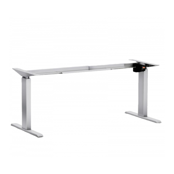
- Page 1 English Deutsch Nederlands Aluforce Pro 140 M Frame for an electro-motorized workstation Assembly Manual Read this manual thoroughly and store in a safe place!
-
Page 2: Table Of Contents
Content GENERAL ............................... 3 Local value of the assembly/operating manual ..................3 Intended use ............................3 Improper use ............................3 Content box ............................4 SAFETY INFORMATION ..........................5 Symbols/warnings ..........................5 Symbols used on the workstation frame ....................5 Organizational measures ........................5 Informal safety measures ........................ -
Page 3: General
1 General 1.1 Local value of the assembly/operating manual The guiding principle for safe use and trouble-free operation of this workstation frame is knowledge of basic safety information and regulations. This assembly/operating manual contains the most im- portant information needed for assembling and operating the workstation frame safely. This assem- bly/operating manual, in particular the safety information contained herein, must be observed by any person building the frame and working on the finished surface. -
Page 4: Content Box
1.4 Content box Part name Top support Foot Hexagon shaft Axle Drive Crossbar L-Bracket Foot adjusters Tools Mounting hardware kit Drive unit Power supply Holder Up/down switch Cable up/down switch Power Cord 10.1 2x Set Screw M6x6 10.2 4x Set Screw M6x20 10.3 6x Flange Nut M6 10.4... -
Page 5: Safety Information
2 Safety Information 2.1 Symbols/warnings The assembly/operating manual uses the following terms and signs to indicate dangers: This symbol indicates an immediate threatening situation for any person’s life or health. Failure to adhere to such information may have serious consequences for health, or could even result in life-threatening injury or death. -
Page 6: Use Of The Workstation Frame
2.8 Use of the workstation frame Do not allow children to use the workstation frame unsupervised. Children may be unaware of the dangers presented by the workstation frame. They would be in serious danger of injur- ing themselves, possibly even with fatal consequences. Further adjustment must then be im- possible as a safeguard against use by children. -
Page 7: Assembly
3 Assembly Before attempting assembly, read the safety information in Section 2. 3.1 Checking the items supplied Carefully open the cardboard packaging. In doing so, do not use any long knife blades. They may damage the components inside. Check the parts supplied against the list in Section 1.4 Items supplied. -
Page 8: Mounting The Crossbar
3.4.2 Mounting the Crossbar Assemble the following components: Part name Pre-assembled Crossbar Pipe Key M10 Allen key M3 10.2 Set Screw M6x20 10.3 Flange Nut M6 Cellulose Tape Photo 1 Remove the transparent cellulose tape on the crossbar bracket before mount to the ... - Page 9 Important !!! Do not fully tighten the flange nut. Prevent the plate in crossbar bracket from falling off! Photo 3 Place the pre-assembled crossbar over the set screws. Place the 4 flange nuts on the set screws. ...
-
Page 10: Mounting The Feet
3.4.3 Mounting the Feet Assemble the following components: Part name Foot Foot adjusters Spanner M10 / Pipe Key M10 10.4 Hex Bolt M6x25 10.5 Washer M6 Allen Key M3 Pipe Key M10 Photo 5 Turn the pre-assembled legs and crossbars up-side-down (with 2 persons). ... - Page 11 Tighten the set screws. Tighten the flange nuts Photo 7 Turn the frame back on its foot (with 2 persons). Now only :- - FIRMLY tighten the 4 set screws on the crossbar bracket with Allen Key M3. - FIRMLY tighten the 4 flange nuts on the crossbar with Pipe key M10.
-
Page 12: Mounting The Hexagon Shaft
3.4.4 Mounting the Hexagon Shaft Assemble the following components: Part name Hexagon shaft Axle Drive Spanner M10 Drive unit Be aware that both legs are completely in the lowest position. Be aware that the drive units have not been connected to a power source before the complete assembly has been done . - Page 13 Photo 10 Slide the axle drive over both hexagon shafts. Photo 11 Slide both hexagon shafts inward, until they are flush with the outside surface of the leg. ...
-
Page 14: Mounting The Top Supports
3.4.5 Mounting the Top Support Assemble the following components: Part name 02 Top support 09 Allen Key M3 10.8 CSK M5x25 Photo 12 & 13 Position the top support, like photo 12, in relation to the crossbars Connect each top support to a leg with 4 CSK screws ... -
Page 15: Mounting The Drive Unit
3.4.6 Mounting the Drive Unit Assemble the following components: Part name L-Bracket 10.8 CSK M5x25 Allen Key M3 Spanner M10 10.6 Bolt M6x80 10.5 Washer M6 10.3 Flange nut M6 10.7 Plastic spacer 15 14 16 17 Photo 14 Slide the long bolt (M6x80mm) with a washer through the specific hole in the drive unit. ... -
Page 16: Adjustment Of The Frame Width
3.4.7 Adjustment of the frame width Pull the frame outward to the required wide (see chapter 3.4.1 Pre-assembly of the Crossbar) Tighten the set screws in the bottom crossbar and pinching nuts on the axle drive with the Spanner M10 only now. -
Page 17: Connecting The Cables Drive Unit
3.4.8 Connecting the Cables Drive Unit Assemble the following components: Part name Power supply Up/down switch Cable up/down switch Power Cord 19 Keep the Jumper in the Drive Unit. Without this plug the Drive Unit will not work. Jumper Keypad Cable Powersupply Photo 19 Connect the cable up/down switch to the up/down switch and the correct connector of the... -
Page 18: Frame Test Without Tabletop
3.4.9 Frame test without tabletop Photo 21 Press “UP” button, the frame goes up. Release the button, the frame stops. Press “DOWN” button, the frame goes down. Release the button, the frame stops. UP DOWN Make sure that the workstation frame can move correctly and freely at all times. -
Page 19: Technical Specifications
4 Technical Specifications Frame for Electro Motorised Workstation Assembly Manual version P19300-1EN-DE-NL Year of construction 2016 Production country Malaysia System 1-step, external drive Material Aluminium, steel and plastic Stroke (max.) 46 cm Frame load (max.) 60 kg Frame weight ± 22 kg Speed 0 kg frame load ±... - Page 20 4 Technical Specifications (* General Tolerance = ± 1 cm) 110 - 170 cm 60 cm 75 cm Minimum frame height 70 cm Maximum frame height Maximum stroke 46 cm Frame Width 110 - 170 Frame Depth Minimum Tabletop Depth Maximum load...
-
Page 21: Operation And Indicators
5 Operation and Indicators Observe the provisions of Section 2 Safety Information on page 5, in particular: Do not leave children unsupervised with the workstation frame. Children may be unaware of the dangers presented by the workstation frame. They would be in serious danger of in- juring themselves, possibly even with fatal consequences. -
Page 22: Customer Service
6 Customer Service Make sure you have the frame information at hand when contacting your dealer Retailer: 7 Manufacturer Actiforce International B.V. Xenonweg 11 3812 SZ Amersfoort The Netherlands +31 (0)33 4600120 www.actiforce.com info.holland@actiforce.com 8 Recycling 8.1 Taking the workstation out of active duty Pull the power plug out of the electricity socket.
Need help?
Do you have a question about the Aluforce Pro 140 M and is the answer not in the manual?
Questions and answers
Do you have a diagram of how the internals go back together for each piece. Also can you give me info on who and where to buy a new up/down pushbutton control with the 24-36'' 4-conductor cord.