
Related Manuals for Nuova Mondial Mec MANTA COMPAT 200 LX

Summary of Contents for Nuova Mondial Mec MANTA COMPAT 200 LX
- Page 1 ORIGINAL INSTRUCTIONS ENGLISH User Instructions and Maintenance Manual NUOVA MONDIAL MEC Srl Bridge Saw Model: ________________________ Serial No.: ____________________ Construction Year :__________...
-
Page 2: Table Of Contents
Summary Summary..........................2 Document Revision ......................6 Information and Management of the Document ............7 Purpose of the User Instructions and Maintenance Manual ........8 Preservation of the User Instructions and Maintenance Manual ......9 How to read the User Instructions and Maintenance Manual ........9 Conventions used .................... - Page 3 5.12 Individual Protection Devices ................29 Out of Service and Demolition ..................30 Introduction ......................31 Setting of the Machine to Insulation ..............31 6.2.1 Insulation of the Machine ................31 Out of Service for Inactivity ..................31 Demolition ......................31 Materials used .......................
- Page 4 9.4.2 Unpacking the Machine .................. 50 9.4.3 Positioning of the Machine ................50 9.4.4 Removal of the cutting head blockage ............51 9.4.5 Electrical connection ..................51 9.4.6 Power supply outlet connection to the electrical panel ........52 9.4.7 Check and control of power supply stages ............52 Wiring Diagrams ....................
- Page 5 11.4.1 Verification and tension of the leading group travel belt ........ 70 11.4.2 Replacement of the toothed belt ..............70 11.4.3 Adjustment of the head wheels ..............71 11.4.4 Cleaning ......................72 11.5 Shutting down – Inactivity of the Machine ............72 11.6 Maintenance Register ..................
-
Page 6: Document Revision
1 Document Revision Revision Description Revision Date Revision Revisor Index Initials First Issue 01/11/2013 1003_R00_IT... -
Page 7: Information And Management Of The Document
2 Information and Management of the Document Revision Revision Description Revision Date Revisor Index Initials First Issue 01/11/2013 Pagina 7 di 87 3004_R00_IT... -
Page 8: Purpose Of The User Instructions And Maintenance Manual
Nuova Mondial Mec srl – Via La Pastora, 82 Cerasolo di Coriano – 47853 Rimini (Italy) – called from now onwards: “Manufacturer”- realized these instructions. This manuali s created in order to be used together with the machine here described; it must always be with the machine, even in case of transfer to other user. -
Page 9: Preservation Of The User Instructions And Maintenance Manual
Time spent reading this information will help to avoid risks to the health and safety of people and economic damage. 2.2 Preservation of the User Instructions and Maintenance Manual The Instructions and Maintenance Manual, named Instructions from now onwards, must always accompany the machine. -
Page 10: Conventions Used
2.4 Conventions used In order to give greater prominence to the texts not to be overlooked, the manual can make use of the following typographic conventions; it is necessary to read the manual very carefully in the sections with the following symbols: CAUTION - DANGER This symbol indicates dangers that must be carefully considered to avoid serious personal injuries... -
Page 11: Upgrade Of The User Instructions And Maintenance Manual
2.5 Upgrade of the User Instructions and Maintenance Manual Each page contains an identification code structured to contain the following information: 1. Numeric code to identify the chapter to which the page belongs 2. Progressive Revision Index 3. Language identification code 4. -
Page 12: Conventional Symbols - Machine Technical Data
Material: product worked by the machine such as tile, granite, marble, ceramic, natural stone. Cutting Blade : circular tool used for cutting Grinding Wheel: circular tool used for profiling and/or making holes on the pieces. Grinding Wheel: circular tool used for polishing the profiled pieces. Diamond Tool: tool composed of two parts : a diamond part, “segment”... -
Page 13: Warranty And Customer Service
3 Warranty and Customer Service Revision Revision Description Revision Date Revisor Index Initials First Issue 01/11/2013 Pagina 13 di 87 3005_R00_IT... -
Page 14: Warranty
Nobody is allowed to change the warranty terms or issue other ones, oral or written, without the written permission of the manufacturer Nuova Mondial Mec Srl Checking at the delivery It is necessary to check the machine when delivered controlling particularly the following points: •... -
Page 15: Customer Service
For every inquiry of technical assistance concerning the machine, it is necessary to indicate all data reported on the identification plate, the approximate working hours and the kind of defect encountered. For every need, refer to the Customer Service of the Manufacturer: Nuova Mondial Mec Srl Via la pastora, 82 47853 - Cerasolo di Coriano... -
Page 16: Main Information
4 Main Information Revision Description Revision Date Revision Revisor Index Initials First Issue 01/11/2013 Pagina 16 di 87 3006_R00_IT... -
Page 17: Manufacturer's Details
4.1 Manufacturer’s Details Nuova Mondial Mec Srl Via la pastora, 82 47853 - Cerasolo di Coriano Rimini- Italy TEL. +39 0541 75 96 88 FAX +39 0541 75 62 38 info@nuovamondilamec.com www.nuovamondialmec.com 4.2 Marking The CE plate placed on the machine identifies the manufacturer and the model of the machine, it is the unique reference authorized by the manufacturer as means of product identification. -
Page 18: Position Of The Machine Plate
Line N° Description Company Name and Address of the Manufacturer Model Machine Type Rated Electric Current of Absorption No. of Phases Weight - kg Short Circuit Current – kA (RMS Sym) Serial No. Construction Year Rated Power of Absorption Rated Voltage of Power Supply Rated Frequency Protection Degree –... -
Page 19: Conformity Declaration
4.3 Conformity Declaration Every Machine is supplied with a Conformity Declaration together with the instructions. Machines are constructed in accordance with essential safety requirements of Community Directives: 2006/42/CE related to the machines 2004/108/CE related to electromagnetic compatibility. The conjecture of conformity to the machine is given also through applicable parts of the regulations, type A and B, harmonized to the declared directives. -
Page 20: Main Safety Regulations
5 Main Safety Regulations Revision Revision Description Revision Date Revisor Index Initials First Issue 01/11/2013 Pagina 20 di 87 3007_R00_IT... -
Page 21: Main Safety Warnings
Main Safety Warnings Even if the installation is effected by the Manufacturer or by authorized Technicians, this documentation must be read before any following operation, in any case. Check that the handbook contains all sheets listed on the Summary inserted at the beginning, and immediately communicate to the Manufacturer the eventual lack or illegibility, even partial, of one of them. -
Page 22: Main Precautionary Measures Of The Machine
The possible need to dispose of the machine with the protective devices and safety excluded, or when it is necessary to use it in safety mode suspended, requires skill and caution by all operators identified and extreme attention by the "Factory Manager "so that the said operator does in this mode only the operations established in full compliance with safety standards. -
Page 23: Safety Warnings For Demolition
Here below warnings and suggestions considered useful for the worker by the manufacturer are reported on the basis of the experience matured through time: Many objects worn by the operator can be dangerous and cause injuries, so take off eventual rings, watches and bracelets;... -
Page 24: Machine Not Powered
Machine not powered The machine not powered is: 1. Machine disconnected from the power supply, the disconnecting switch is on 0 or OFF position; 2. Machine disconnected from the pneumatic supply (*); the feeding line is disconnected or the on-off valve is closed; 3. -
Page 25: Wrong Uses
Wrong Uses Reasonably foreseeable wrong Uses are all uses and behaviors implying a working of the machine besides project limits described in the user instructions and in the technical documentation, particularly: All uses different from the ones expected by the manufacturer; ... -
Page 26: Position Of The Operator
Position of the Operator Main Positions of the Operator are all places where he has to be while the machine is working. The positions indicated refer only to the places to be occupied during normal activity; places to be occupied during maintenance, repair and cleaning operations are not considered in this chapter. The Operator Positions are reported in the Chapter 10 “use of the machine”... - Page 27 Dangers Residual Risks Behaviours to adopt Warning Pictograms Mechanical Nature: Shearing, Keep the hands at a safety abrasion, distance from the tools while Tools while moving tearing, moving. impact Always wait the tool stops before Injuries caused by getting close to the cutting blade accidental contacts or removing the material near it.
- Page 28 Dangers Residual Risks Behaviours to adopt Warning Pictograms Electrical Nature: Electrocution for Always check the efficiency of the direct or indirect electric parts; the insulation of the contact cables that must be perfect; the integrity of the motors and pumps for the cooling system;...
-
Page 29: Safety Devices
5.10 Safety Devices The machine is equipped with safety and protection devices in order to reduce the risk. The devices are described in Chapter 7 “description of the machine”. Please refer to the complete description in this chapter. 5.11 Information and Warnings on the Machine – Symbols information warnings given... -
Page 30: Out Of Service And Demolition
6 Out of Service and Demolition Revision Revision Description Revision Date Revisor Index Initials First Issue 01/11/2013 Pagina 30 di 87 3008_R00_IT... -
Page 31: Introduction
Introduction The machine is manufactured and constructed according to criteria of strength, duration and flexibility allowing many years, productively. When its service life is over, the machine should be turned off, that means it should be taken out of service so that it cannot be anymore used for the purposes for which it was designed and built. Same Deactivation Procedures... -
Page 32: Materials Used
Carry all materials to proper collection centers on the basis of National Laws of the Country where disassembly takes place. Do not throw materials or parts of machines in the environment. Reusing of Parts Reusing of some parts of the machine, both mechanical parts and raw materials for other constructions, subordinate total... -
Page 33: Description Of The Machine
7 Description of the Machine Revision Description Revision Date Revision Reviser’s Index Initials First Issue December 20, 2013 Page 33 of 87 301006_R00_IT... -
Page 34: Description Of The Machine
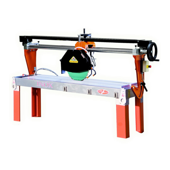
Description of the Machine Machine MANTA COMPAT 200-250-300 is an electrical sawing machine that allows the cut of each stony material for the construction industry. The main feature that distinguishes the MANTA COMPAT 200-250-300 machine lies in the affordability, versatility, simplicity and, at the same time, robustness. Suitable for both small workshop and large industry. - Page 35 Machine legs Side jambs X-axis limit switch cam Electrical panel for the SA version X-axis advance unit – the SA version Z-axis lifting unit - the SA version Head cart Shelves Diamond disk guard Diamond disk engine X-axis advance unit – the LX version Head sliding rail Z-axis lifting unit - the SA version Shoulders...
-
Page 36: Accessories Supplied With The Machine
The identification plate sowing the type or model of machine with its serial number, name and engine data is posted on the electrical panel of the machine. 7.1.2 Accessories Supplied with the Machine Included with the machine, the following material is supplied: - Set of service keys - 1 submersible pump. -
Page 37: Operating Principle
Operating Principle This type of machine is designed for cutting, exclusively water squaring, of stone and similar materials with diamond discs commercially available but excluded from the supply. It is used raised from the ground with removable fixed angular supporting legs necessary for the transport phases. -
Page 38: Overall Dimensions
7.3.1 Overall Dimensions The following are the overall dimensions of the machines in the environment. Dimensions in mm. Image 4 Overall dimensions Page 38 of 87 301006_R00_IT... -
Page 39: Transportation And Storage
8 Transportation and Storage Revision Description Revision Date Revision Reviser’s Index Initials First issue December 18, 2013 Page 39 of 87 301007_R00_IT... -
Page 40: Safety Requirements For Handling
Safety Requirements for Handling Run the lifting and the handling in accordance with the information provided by the Manufacturer and marked on the packages, on the machine and in the instructions for use. • When handling, if conditions require, use one or more operators to receive appropriate alerts. -
Page 41: Storage
Image 5 – Types of Packaging The removed components are suitably packed and protected. Where it becomes necessary, general information necessary for the protection of the machine can be reported on the packaging in the form of normalized pictograms. FRAGILE PROTECT FROM RAIN 55°C MAXIMUM AND MINIMUM STORAGE TEMPERATURE... -
Page 42: Transportation Modes
- It is forbidden to deposit the machine in positions where it is directly exposed to rain or high temperature ranges. - Grease the unpainted parts. Transportation Modes 8.4.1 Safety Requirements Before lifting check the load center position. It is always necessary to dissemble the support legs in order to avoid that the latter may become damaged during the movements. -
Page 43: Lifting - Handling With Lifting Equipment
8.4.5 Lifting – Handling with Lifting Equipment 8.4.5.1 Lifting for Machines without Packaging. The machine can also be transported by forklift or lifted by crane or bridge crane. The machine devoid of legs remains raised from the ground, to the standard height (10 cm) required for the passage of the forks for the forklift. -
Page 44: Preliminary Checks
For longer trips it is better to use a wooden packaging in order to protect the delicate parts such as electrical panel, engine, etc. Use the original if it is preserved, but only if in good conditions. 8.4.5.2 Lifting from above for machines with packaging. The procedure is valid for machines with any type of packaging provided. -
Page 45: Unpacking And Disposal Of Packaging
Unpacking and Disposal of Packaging The machine must be unpacked taking care not to cause damage to the structures or components. Be careful when using knives for cutting the packaging, they can cause damage to parts of the machine and unsightly scratches. The packaging material must be properly disposed of in accordance with applicable laws. -
Page 46: Installation
9 Installation Revision Description Revision Date Revision Reviser’s Index Initials First issue December 17, 2013 Page 46 of 87 301008_R00_IT... -
Page 47: Safety Requirements For The Installation
Safety Requirements for the Installation The installation and electrical connections must be performed, as regards the machine, according to the indications provided by the Manufacturer. You must also take account of all national regulatory and legislative requirements of the country where the machine is installed, performing all the operations of installation and connection to perfection. -
Page 48: Admissible Ambient Conditions
9.3.1 Admissible Ambient Conditions The machine must be installed by following the instructions below: a) Voltage and frequency of the supply connections (refer to the values shown on the EC plate) b) Temperature: - 5 ° C + 45 ° C c) Altitude: up to 1000 ml. -
Page 49: Installation
The sound emission levels depend on the place of location of the machine and on correct maintenance of all its parts. Not being the Manufacturer, Nuova Mondial Mec S.r.l, the constructor diamond disks, obviously cannot guarantee the compliance of materials of third party production. The noise data can vary depending on the type of blade mounted. -
Page 50: Unpacking The Machine
9.4.2 Unpacking the Machine For the unpacking procedure in the wooden case: • Loosen the bolts holding one long side of the case • Remove the wooden panel. • Remove from above the shelf any materials that are traveling with the machine or extra accessories. -
Page 51: Removal Of The Cutting Head Blockage
9.4.3.2 Leveling The legs in the base of machine are provided with holes for fixing the same to the floor by means of bolts, not supplied, which can also act as registers for leveling. 9.4.4 Removal of the cutting head blockage The machine is supplied with a special wooden blockage placed under the head of the cutting group (diamond disk), so as to prevent movement and damage to the head during transport, it is thus required to remove such blockage before performing any manual movement of the mechanical parts. -
Page 52: Power Supply Outlet Connection To The Electrical Panel
9.4.6 Power supply outlet connection to the electrical panel The electrical connection of the machine must be carried out under the responsibility and liability of the customer and performed by a person knowledgeable and informed about electrical hazards and authorized by the client (employer). The power supply of the machine must be carried out via the connection of the 4-wire or 5-wire cable with the presence of the neutral conductor of the supply system. -
Page 53: Wiring Diagrams
Wiring Diagrams The circuit diagram of the machine and any inverter manuals (only for machines with electronic variation of the knife blade speed) are located inside the electrical panel. After commissioning the machine it is advisable to store it in a dry place, available for possible interventions. -
Page 54: Use Of The Machine
10 Use of the Machine Revision Revision Description Revision Date Reviser’s Index Initials First Issue December 16, 2013 Page 54 of 87 301009_R00_IT... -
Page 55: Safety Requirements For The Proper Use
10.1 Safety Requirements for the Proper Use - Do not allow the use of the machine to minors, incompetent persons, and persons who present physical and / or psychological problems. - Move the strangers away from the surrounding work space to a distance of at least 5 m from the machine. -
Page 56: Operator Workstation
10.2 Operator Workstation Refer to Image 10 for the workstation that the operator must occupy during the cutting process - Provide appropriate space for storage both for pieces to be processed, and for those already processed (possibly also using appropriate containers). - Do not perform any work operation or intervention on the rear side of the machine without it being turned off from the power supply. -
Page 57: Selection And Installation Of Tools
10.5.1 Selection and Installation of Tools Always make sure you turn off the machine before touching the moving parts of the machine, always by unplugging it from the power mains. General rules for the selection of the tools: • The tools must always be checked and not have any defect. •... -
Page 58: Filling Of The Tub With Coolant Water
Before mounting the disk clean the flange and pressure plate flange If you notice any debris, rust or oxide, eliminate them with very fine sandpaper. Clean in the same way also the parts of the disc that are in contact with the flange and the pressure plate flange. -
Page 59: Disk Cutting Height Positioning
10.5.5 Disk Cutting Height Positioning The maximum depth of the cutting tool (disk blade), as well as the maximum free lift between the work surface and the electric motor, are fixed values predetermined by the manufacturer according to the model of the machine indicated in Chapter 2 of the manual under the machine technical data section. It is therefore recommended to always check whether these characteristics are compatible with the size of the material you intend to cut. -
Page 60: Preparation And Commissioning
10.5.7 PREPARATION AND COMMISSIONING 10.5.7.1 Preliminary checks Before starting up the machine, you must perform a series of checks and controls to prevent errors or accidents during commissioning. - Provide appropriate space for storage both for pieces to be processed, and for those already processed (possibly also using appropriate containers). - Page 61 adjusting the depth of cut using the rise / descent hand wheel of the head, so as to avoid the tool overheating and damage to the electric motor. Perform the start-up and shutdown of the machine with the disk in a position where it has no contact with the workpiece or machine components.
- Page 62 10.5.9.2 Version No. 2 - Semi-automatic Description of the command and control operator panel Image 15 Description of the Command Panel 10.5.9.2.1 Description of the Command Operator Panel Emergency stop mushroom button. Correct phases indicator. Voltage presence lamp. Engine blade start / stop. Head speed decrease / increase.
-
Page 63: Unloaded Machine Testing
All operations described below refer to the Image 15 of the Command Panel • Turn the main switch Ref.8 clockwise to position "1". The Ref. 3 network indicator lights up • To control the up and down movement of the head, press the up and down arrow ref. 7, to stop the movement, release the button. -
Page 64: Rules For The Cutting Of The Material
6. The disc remains in motion until you press the Key 0 Ref. 4 to stop it. 7. Once you have completed the cutting, turn off the disc engine and remove the cut material. 10.5.12 Rules for the cutting of the material Start working only when all safety devices have been installed and are ready for operation, never use the machine without all guards having been mounted or if a part of it is missing. -
Page 65: Work Surface Extensor
10.5.13 Work Surface Extensor For processes that require greater space for supporting the material or to facilitate the loading and unloading of the workpiece, the machine is designed to house at the sides of the base, the roller or shelf bench extensor, 1 roller extensor is supplied as a standard (REF. A Image 16 Bench (work surface)extensor ) Image 16 Bench (work surface)extensor Page 65 of 87... -
Page 66: Maintenance And Troubleshooting
11 Maintenance and Troubleshooting Revision Description Revision Date Revision Reviser’s Index Initials First Issue December 17, 2013 Page 66 of 87 301010_R00_IT... -
Page 67: Maintenance And Cleaning
11.1 Maintenance and Cleaning 11.2 Introduction All those who perform maintenance must protect and ensure the maximum protection to people exposed to danger. Persons who perform any maintenance operations must first remove all sources of power and the power supply by disconnecting the power plug from the power outlet. Such operations, even if simple, must be performed by Qualified Personnel. - Page 68 For convenience and greater cleanliness remove the front nozzle, where the water line is connected, by unscrewing the screw ref. A counterclockwise ref. C and pull it out ref. B; Spray them with clean water and reassemble. Image 18 Dismantling the pump 4] In the case of prolonged stoppages of the machine, before putting it in work extract the pump and ensure that the deposits have not blocked the fan, in each case run the fan with hands by removing the front part of the same (as in the previous paragraph).
-
Page 69: Lubrication And Greasing
11.3.2 Lubrication and greasing The time intervals described refer to machines operating in conditions of 8 hours daily or 40 hours weekly. It is recommended not to use, as much as possible, compressed air since the air jet promotes the inclusion of particles of material resulting from cutting, inside mechanical components favoring wear. -
Page 70: Extraordinary Maintenance And Cleaning
11.4 Extraordinary Maintenance and Cleaning Extraordinary maintenance activities are all activities other than routine maintenance. Extraordinary maintenance can only be performed by highly skilled operators with in-depth knowledge of the machine. The following are the operations for which it is necessary to place a request for intervention to our Technical Assistance, but may also be carried out by qualified personnel authorized by the Manufacturer. -
Page 71: Adjustment Of The Head Wheels
11.4.3 Adjustment of the head wheels After a long period of work, slightly curved cuts may appear. In this case, check that the head is not running, hold a chrome bar with your hands and yank it transversally to the cutting axis. If you feel a slight swing, a gear, proceed to the tightening of the wheels, which through use may have slightly worn. -
Page 72: Cleaning
11.4.4 Cleaning Perform the daily cleaning of the machine in order to avoid the accumulation of residues on the work surface where the material to be processed is placed. Proceed by removing the power supply by putting the switch to [0 OFF], remove debris from the work surface and wash the work surface with a jet of water being careful not to direct the jet on electrical equipment. -
Page 73: Diagnostics And Troubleshooting
11.7 Diagnostics and Troubleshooting In the cases described in the following tables, the possible cases of failure and / or problems are presented and for each of them the sequence of controls to be performed in order to remove the causes that may have caused the problem is listed. -
Page 74: Assistance Service
voltage sag. reset it by pressing the reset button. Lack of electrical energy in one Make sure there is on-line or more phases. voltage on the two or three phases. Process pieces in relation to the engine capacity as described in technical specifications. -
Page 75: Parts And Accessories
12 Parts and Accessories Revision Revision Description Revision Date Reviser’s Index Initials First Issue December 17, 2013 Page 75 of 87 301011_R00_IT... -
Page 76: Parts
12.2 Parts The parts and components which make up the machine, are shown in the exploded diagrams below, it is thus necessary to refer to these directions included at the end of this manual. 12.2.1 How to Order Spare Parts Locate the piece on the drawing, note the corresponding number and request it from your local reseller specifying the type, the model of the owned machine and serial number. - Page 77 CUSTOMER’S DATA COMPANY: APPLICANT’S FULL NAME: ADDRESS: MACHINE DATA MACHINE MODEL SERIAL NUMBER VOLTAGE REFERENCE NO. IN THE QUANTITY NOTES DRAWING Image 22 Spare Parts Request Order Form Page 77 of 87 301011_R00_IT...
- Page 78 Page 78 of 87 301011_R00_IT...
- Page 79 Page 79 of 87 301011_R00_IT...
- Page 80 Page 80 of 87 301011_R00_IT...
- Page 81 Page 81 of 87 301011_R00_IT...
- Page 82 Page 82 of 87 301011_R00_IT...
- Page 83 Page 83 of 87 301011_R00_IT...
- Page 84 Page 84 of 87 301011_R00_IT...
- Page 85 Page 85 of 87 301011_R00_IT...
- Page 86 Page 86 of 87 301011_R00_IT...
- Page 87 12.3.1.1 Page 87 of 87 301011_R00_IT...
Need help?
Do you have a question about the MANTA COMPAT 200 LX and is the answer not in the manual?
Questions and answers