Table of Contents
Advertisement
Available languages
Available languages
Quick Links
Advertisement
Table of Contents

Summary of Contents for Simon Scena
- Page 1 MANUAL Y GUÍA DE INSTALACIÓN SCENA MANUAL AND INSTALLATION GUIDE...
-
Page 2: Table Of Contents
CAST Índice 1. Introducción Scena 1.1 Funcionalidades 1.2 Dispositivos Scena 1.2.1 Consola central Touch Light Manager 1.2.2 Touch Light Keypad 1.2.3 Módulos de potencia 1.2.4 Referencias compatibles con Conversor señales digitales 1.2.5 Referencias compatibles con Conversor señales analógicas 2. Conexiones Scena 2.1 Conexionado general... - Page 3 CAST 5.4.6 Entrada Analógica 5.4.7 Entrada digital 5.4.8 Botonera 5.4.9 Reg Ext 5.4.10 Módulo regulador transformador electrónico en paralelo (Paralelo) 5.5 Creación de grupos 5.6 Regulación de grupos 5.6.1 Grupo tipo Luces 5.6.2 Grupo tipo Persianas 5.6.3 Grupo tipo RGB 5.6.4 Grupo tipo Mixto 5.7 Creación de escenas 5.8 Configuración de escenas...
- Page 4 CAST...
-
Page 5: Introducción Scena
· Actualizar la versión más reciente de Scena con una memoria flash (Pen drive). · Cargar y guardar programaciones. Scena es un sistema flexible y adaptado a todo tipo de cargas, desde halógenas hasta LED, y desde protocolo 1-10V hasta DMX, DALI o PWM. -
Page 6: Funcionalidades
CAST 1.1 Funcionalidades El control total sobre la iluminación que proporciona Scena se efectúa mediante funciones sencillas hasta las funciones más innovadoras del mercado y todo desde un solo producto, la consola central Touch Light Manager. Escenas lumínicas Ambientaciones a medida, desde una iluminación tenue y relajante hasta otras basadas en blancos y en colores para transmitir emociones. - Page 7 CAST Escena lumínica Control individual de varios canales o grupos para conseguir una ambientación lumínica global. Escena colores Control individual o en grupo de luminarias RGB y convencionales para conseguir una ambientación lumínica global. Secuencias Control dinámico para variación de escenas en función del tiempo. Simulación de presencia Activación o desactivación inteligente de canales para simular la presencia en un local o vivienda.
-
Page 8: Dispositivos Scena
CAST 1.2 Dispositivos Scena 1.2.1 Consola central Touch Light Manager Permite programar y controlar todos los elementos del sistema. · Alimentación directa a 100V/230V. · Pantalla táctil. · Acabado grafito y blanco. · Proporciona alimentación a 16 módulos de potencia (Para más de 16 es necesario fuente de alimentación Ref. -
Page 9: Módulos De Potencia
CAST 1.2.3 Módulos de potencia · Elementos que proporcionan alimentación y potencia a diferentes tipos de cargas/luminarias. · Instalación en falso techo o carril DIN. · Pueden funcionar como reguladores convencionales sin necesidad del elemento Touch LightManager. · Entrada auxiliar en cada elemento para regulación a través de pulsadores convencionales sin luminoso (máximo 5). - Page 10 CAST Conversor señales digitales Traduce a DMX una señal digital tipo 0 a 230V 2 entradas digitales independientes Ejemplos: - Vincular desde la consola una escena a un detector de presencia - Al introducir la tarjeta en el tarjetero se activa la escena “Bienvenida” Ref.
-
Page 11: Referencias Compatibles Con Conversor Señales Digitales
CAST 1.2.4 Referencias compatibles con Conversor señales digitales (Ref. 89000301-039) Detector de presencia 75343-39 Ref. Detector de presencia para empotrar 10302-31 Ref. Interruptor para tarjeta codificada 75559-39 Ref. *Compatible con cualquier mecanismo que proporcione una salida a 230V. 1.2.5 Referencias compatibles con Conversor señales analógicas (Ref. 89000302-039) Sensor de luminosidad y presencia Necesita fuente de alimentación Ref. -
Page 12: Conexiones Scena
CAST 2. Conexiones Scena 2.1 Conexionado general Observaciones generales · La instalación en la parte de comunicación se debe de realizar en serie. · Máximo 16 dispositivos con la alimentación propia de consola (dependiendo de distancia de cableado). Nº de módulos Distancia máxima del último módulo... - Page 13 CAST Distribución en las conexiones · La instalación del sistema Scena se caracteriza principalmente por dos tipos de conexiones muy diferenciadas. - Cable de comunicaciones: incluye alimentación y datos. Ha de ser un cable cat5 FTP flexible y multifilar. - Cable de potencia: fundamental para el regulador ya que le aporta tensión para su funcionamiento.
- Page 14 CAST Instalación en serie La instalación ha de ser en serie, y como primer elemento la consola central. De cada dispositivo debe entrar un cable de comunicaciones y salir otro cable por el mismo conector hacia el siguiente dispositivo, de igual manera con el par de cables de alimentación. IMPORTANTE Se recomienda el uso de un cable FTP categoría 5 de dos pares (mínimo) flexibles y multifilares para la conexión del bus 485.
-
Page 15: Conexionado De Cada Dispositivo
CAST 2.2 Conexionado de cada dispositivo 2.2.1 TouchLightManager 2.2.2 TouchLight Keypad 2.2.3 Módulo interruptor/conmutador electrónico... -
Page 16: Módulo Regulador Transformador Electrónico
CAST 2.2.4 Módulo regulador transformador electrónico 2.2.5 Módulo regulador transformador electrónico paralelizable Permite aumentar la potencia máxima admitida en un módulo individual hasta los 750W. Los equipos paralelizados deben ser dados de alta en la consola manualmente y como tipo PARALELO. (Ver en página 27 Alta manual de canales). -
Page 17: Modulo Regulador 0-10V
CAST 2.2.6 Modulo Regulador 0-10V 2.2.7 Modulo control de Persianas... -
Page 18: Conversor Señales Analógicas
CAST 2.2.8 Conversor señales Analógicas *Sensor de luminosidad Ref. 9000570-039, necesita fuente de alimentación Ref. 81222-38. 2.2.9 Conversor señales Digitales 2.2.10 Conversor DMX-PWM... -
Page 19: Conversor Dmx-Dali
2.2.11 Conversor DMX-DALI 2.2.12 Dispositivo Externo Cualquier dispositivo DMX que incorpore switch de direccionamiento es compatible con el sistema Scena. B = DMX-, A=DMX+, -=GND Los dispositivos externos DMX que no tienen GND común, no son recomendables ya que pueden ocasionar fallos en el sistema. -
Page 20: Ejemplo Conexionado Tipo
CAST 2.3 Ejemplo Conexionado Tipo *Conectar la malla a un único punto de la instalación y mantener la continuidad en el resto de la instalación... -
Page 21: Alta Dispositivos
Para ello es necesario conocer el funcionamiento del switch. 3.1 Funcionamiento del switch (Instalador) El switch es un método de direccionamiento de los dispositivos que forman Scena. A continuación se detallarán las características de éste. · Del pin 1 al 9 hay 512 (0-511) canales a activarse por binario, que se pueden asignar a diferentes dispositivos. -
Page 22: Ejemplos
· Siempre que se quiera eliminar un dispositivo que se ha encontrado de forma automática, se tiene que borrar previamente del sistema. En el caso de la botonera, es necesario borrar el canal en Scena, pues sino la botonera guarda el canal con el que se ha dado de alta. -
Page 23: Preguntas Frecuentes
CAST 4. Preguntas frecuentes Tengo un dispositivo y no me lo detecta. · Comprobar cableado de alimentación y comunicación. · Comprobar polaridad de A y B. · Comprobar que no tenga el mismo canal que otro dispositivo. Se encienden 2 dispositivos al mismo tiempo y no tienen relación. ·... -
Page 24: Manual De Usuario
CAST 5. Manual de usuario Para una buena instalación con Scena se han de tener en cuenta unas directrices previas que nos ayudarán a conseguir el objetivo requerido con una gran calidad y rapidez. Una instalación con Scena puede constar de muchas funcionalidades dependiendo de los requerimientos de cada una: Creación Canales... -
Page 25: Acceso A Modo Instalador
CAST La pantalla de Sistema permite al usuario acceder a todos los recursos de Scena que se pongan a su disposición, ya que desde el modo instalador se pueden proteger las aplicaciones (véase más adelante). De la misma forma, tendremos la pantalla de Inicio y de Sistema en modo instalador, a continuación se detallarán los... -
Page 26: Verificación Instalación, Pantalla Test
CAST 5.2.1 Verificación Instalación, Pantalla Test Una vez se está en modo instalador, si se mantiene pulsado el botón de encendido pasamos a la pantalla Login, se nos despliega una nueva opción. Pantalla de Inicio Test Es un método de reconocer los dispositivos conectados y comprobar su comunicación con la pantalla Touch LightKeypad. -
Page 27: Creación De Canales
(es decir, las conectadas a un módulo de potencia regulador, interruptor…). Creación de canales Con Scena se pueden crear los canales de forma automática o manual, para ello es necesario estar en modo instalador: Si en la pantalla de Inicio seleccionamos se entrará... - Page 28 CAST Eliminar canales Seleccionar el icono del canal Si se desea borrar algún canal se debe seleccionar el icono Eliminar en la pantalla canales el icono seguidamente el canal y de canales nuevo el icono borrar. Modo manual de creación de canales Seleccionar Para la creación de canales de forma manual agregar canales...
-
Page 29: Regulación Tipo De Canal
CAST Nombre · Seleccionar Nombre en la pantalla de Canales. · Máximo 9 caracteres. · Idóneamente el nombre debe estar acorde con la instalación. Para aceptar es necesario confirmar en el icono de OK. Confirmar con el icono OK Nombre Número Es necesario para la instalación de un canal, que la dirección de éste sea la correcta en los casos de los conversores de... -
Page 30: Módulo Regulador Transformador Electrónico
CAST 5.4.1 Módulo regulador transformador electrónico Tipo: Dimmer Configuración En modo “general” se permite cambiar la intensidad del canal, deslizando el dedo sobre el slider zona de color gris. Configuración En cambio, la avanzada permite un control mas detallado Cambio de intensidad (sólo en modo administrador). -
Page 31: Modulo Regulador 0-10V
Calibración Para poder controlar una persiana antes de nada es necesa- rio calibrarla, así Scena podrá conocer el recorrido total de la persiana y tener un control de la posición exacto. En la pantalla avanzada (sólo en modo administrador) se permite la calibración de las persianas simplemente apretando... -
Page 32: Conversor Dmx/Pwm
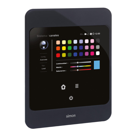
CAST 5.4.5 Conversor DMX/PWM Tipo: RGB Configuración Las luminarias RGB se puede configurar mediante la pantalla “General” o mediante “Avanzada”. En el modo General se puede modificar el color directamente sobre una paleta de Color resultante colores, más control de luminosidad, saturación y matiz del color. -
Page 33: Botonera
CAST 5.4.8 Botonera Tipo: Botonera Configuración En el caso de la botonera, la pantalla general es una reproducción de la botonera, es decir, funcionalmente es una reproducción de ésta. En la pantalla avanzada (sólo en modo administrador) se permite modificar la funcionalidad de cada botón de la botonera, ya sea para introducirle un canal, una escena o un grupo. -
Page 34: Módulo Regulador Transformador Electrónico En Paralelo (Paralelo)
CAST 5.4.10 Módulo regulador transformador electrónico en paralelo (Paralelo) Tipo: Paralelo Configuración Para configurar los reguladores en paralelo, en “general” se permite la regulación directamente. Regulación directa En “avanzada” el tipo de pantalla es la misma que en el caso de módulo regulador trafo electrónico (ver página 29). -
Page 35: Regulación De Grupos
5.6 Regulación de grupos Scena permite regular los grupos como si se tratase de canales individuales, y de la misma forma, es decir, a través de pantalla de configuración “General” o “Avanzada” para cada tipo de grupos, ya sea de Luces, RGB, Persiana o Mixto. -
Page 36: Grupo Tipo Persianas
CAST 5.6.2 Grupo tipo Persianas Tipo: Persianas Configuración general (pulsación prolongada sobre ese grupo): Permite regular o activar/desactivar el grupo y informa sobre el consumo de éste. Para regular, deslizar el dedo por el rectángulo marcado en gris. En configuración avanzada no es configurable ningún tipo de parámetro. -
Page 37: Creación De Escenas
CAST 5.7 Creación de escenas Una escena es un conjunto de canales o grupos con regulaciones fijadas para cada uno de ellos, pudiendo ser estas de distinto valor, de esta manera se pueden combinar diferentes regulaciones para los diferentes canales o grupos. Para acceder a escenas, en la pantalla “Sistema”, se accederá... -
Page 38: Configuración De Escenas
5.8 Configuración de escenas Una vez creada la escena, tal como sucede con los canales y grupos, Scena permite configurar la escena de manera “general” y “avanzada”. Si en la pantalla done aparecen la lista de escenas se accede a una de ellas, mediante pulsación larga, se permite configurar ambas posibilidades. -
Page 39: Creación De Secuencias
CAST 5.9 Creación de secuencias Una secuencia es la sucesión de distintas escenas. De este modo dotamos de dinamismo la iluminación. Para entrar en el menú secuencias, pulsar sobre “Secuencias” en la pantalla “Sistema”. Al acceder al menú secuencias, se accederá a la pantalla donde aparecen las secuencias predefinidas. - Page 40 CAST Modo 2 Cada escena se activará durante un tiempo determinado (Tiempo de paso) sumándose entre ellas durante el tiempo de encendido y apagado (Set time) de cada una de ellas, de manera que la transición de una escena a otra sea progresiva.
- Page 41 (Escena>Tipo>Secuencial). Scena permite modificar la configuración de la secuencia, tanto de una manera “General” como “Avanzada”. En la pantalla general se permite activar o desactivar la secuencia y cambiar su velocidad.
-
Page 42: Creación De Sensores
CAST 5.10 Creación de sensores Un sensor en Scena es un dispositivo capaz de detectar una señal eléctrica a 230V procedente de un detector, pulsador o cualquier otro elemento. Para la creación de un sensor necesitamos un módulo Scena (Módulo conversor de señales digitales) y haber dado de alta un canal de tipo “digital”. - Page 43 CAST 2. Tipo de sensor Hay que diferenciar el tipo de sensor según sea pulsador o detector y según su contacto, diferenciando NA o NC Las funcionalidades variarán dependiendo del tipo de sensor. 3. Añadir canales Relaciona éste sensor con su entrada a la consola, es decir, con el canal de entrada digital.
-
Page 44: Configurar Sensores
CAST 5.11 Configurar Sensores Previamente se debe haber dado de alta un canal tipo digital (ver página 27), y haber creado un sensor con esa entrada del canal digital (ver página 39). Se debe diferenciar entre dos tipos de sensores, tipo pulsador o bien tipo detector. Para acceder al menú... -
Page 45: Creación Clc
únicamente lo necesario para nuestras necesidades. Para la creación de un CLC es necesario tener en la instalación un sensor analógico y haber instalado un dis- positivo Scena (Módulo de entradas analógicas). Es necesario haber dado de alta un canal como entrada analógica (ver página... - Page 46 CAST Para dar de alta un CLC en el Scena es necesario seguir los pasos que se describen a continuación: 1. Nombre CLC Tenemos un máximo de 9 caracteres nombre el grupo deseado. De la A-Z y del 0-9. Para confirmar pulsar OK.
- Page 47 EQ Max y EQ Min es el rango de iluminación del sensor, para ello es necesario consultar las características técnicas de éste. En éste caso se utiliza el sensor de luminosidad SIMON Ref. 9000570-039. El rango de éste es (0-1000Lux) y salida de 0-10V EQ Max: Rango de luminosidad máxima, en este caso 1000 lux.
-
Page 48: Simulación De Presencia
CAST 5.13 Simulación de presencia La simulación de presencia es un método de simulación que activa o desactiva aleatoriamente canales o gru- pos, y que permite realizar una simulación para que parezca que la vivienda esta habitada. Un ejemplo seria encender las luces de algunas estancias durante diferentes periodos de tiempo. Acceder a Presencia a través de la pantalla Sistema, se establece la pantalla de configuración General, en la cual podemos activar y desactivar su estado y duración. -
Page 49: Eco
CAST 5.14 ECO Eco es un sistema de control de la potencia consumida de la instalación. Permite fijar unos límites de potencia consumida, de tal manera que no se permite superarlos. Además se puede limitar toda la instalación o solo canales concretos. Se puede programar distintas prioridades para que en el caso de sobrepasar el límite se desconecten, o bien reduzcan su potencia unas u otras luces. -
Page 50: Calendario
Con lo cual, se puede programar para día y hora la activación de un canal, grupo, escena y secuencia, ade- más de poder activar o desactivar el modo CLC, Presencia o ECO. Para dar de alta una programación en el Scena es necesario seguir los pasos que se describen a continuación. - Page 51 CAST 2. Elementos Añadir elementos. Se pueden añadir tanto, canales, grupos, escenas, secuencias, CLC, Presencia o ECO a la programación horaria. Para incluirlos en la programación se debe desplazar el objeto a la lista de la derecha. Para guardar las modificaciones pulsar Confirmar. 3.
-
Page 52: Excepciones
CAST 5.15.1 Excepciones Se pueden realizar excepciones de las programaciones horarias que se hayan realizado. Por ejemplo días festivos que se desee anular la programación horaria y semanal realizada en Calendario. Al acceder a Excepciones, la pantalla general sirve para visualizar las excepciones realizadas. -
Page 53: Configurar Pantalla De Inicio
CAST 5.16 Configurar pantalla de inicio Una vez dentro del modo instalador, en la pantalla Inicio acceder a Agregar e inmediatamente se accede a la pantalla Sistema donde se puede seleccionar que función se desea incorporar, siguiendo con el ejemplo, si se pulsa Canales, saldrá... -
Page 54: Guardar
CAST 5.17 Guardar Scena dispone de guardado automático, en caso de bajada de tensión o corte del suministro eléctrico, al volver la tensión Scena conservará la programación realizada. En la pantalla “Sistema”, acceder a “Guardar”. El Sistema realiza guardados automáticos cada 30segundos. -
Page 55: Idioma
Scena permite configurar su pantalla de reposo. Se puede programar el tiempo de apagado automático entre las opciones, Off, 1 o 5 minutos. Scena permite que en su pantalla de reposo aparezca el logo SIMON Scena, para ello se puede habilitar o deshabilitar con la opción Scena. -
Page 56: Permisos
Posición C: El usuario puede activar o desactivar, además de modificar sus parámetros y visualizar su estado. 5.18.5 USB Permite cargar y grabar la configuración del Scena en una memoria USB. De esta manera se permite guardar una programación y trasladarla a otro Touch Light Manager. -
Page 57: Actualizar Fw
USB, es decir no deben estar dentro de carpetas en la memoria USB. 5.18.7 Reset Permite resetear la configuración que se haya realizado en Scena. Reset de Funciones Resetea las funciones creadas volviendo a la configuración predeterminada sean canales, grupos, escenas, etc. -
Page 58: Avisos
5.18.8 Avisos Esta pantalla permite verificar la instalación, ya que detecta fallos en la instalación, ya sea por pérdida de comunicación y por pérdida de potencia de los módulos Scena. Fallo de comunicación Si es un fallo de comunicación aparecerá Comms y la dirección en el aviso. -
Page 59: Anexo. Instalación Prototipo
CAST Anexo I: Instalación Prototipo Índice 1. Introducción 2. Conexionado tipo 3. Direccionamiento físico de los canales 4. Programación en la consola 4.1 Acceso modo instalador 4.1.1 Comprobación instalación, Pantalla Test 4.2 Creación de los canales 4.3 Configurar pantalla de Inicio 4.4 Configurar entrada de pulsador 1. -
Page 60: Conexionado Tipo
CAST 2. Conexionado tipo... -
Page 61: Direccionamiento Físico De Los Canales
CAST 3. Direccionamiento físico de los canales Asociar una dirección a cada dispositivo, teniendo en cuenta los elementos como los conversores que deben tener direccionamiento superior a 20 para evitar interferencias. Por tanto: Dispositivo Dirección Pines del switch a ON Módulo regulador transformador electrónico Módulo de entrada digital... - Page 62 Si se pulsa al icono “lista” se accederá a la pantalla “sistema” La pantalla de Sistema permite al usuario acceder a todos los recursos de Scena que se pongan a su disposición. 4.1 Acceso modo instalador Una vez conocidas las pantallas básicas del sistema, a continuación se detallarán los pasos para una correcta y sencilla instalación.
-
Page 63: Acceso Modo Instalador
CAST Seguidamente al seleccionar Login se pasará a una pantalla para la introducción de la contraseña, la predeterminada es 1,2,3 y 4 (los 4 primeros botones de izquierda a derecha / arriba y abajo por orden). Una vez introducida la contraseña aparecerá la pantalla de inicio de instalador con nuevas herramientas del sistema: Además, siempre que nos encontremos en modo instalador, aparecerá... -
Page 64: Creación De Los Canales
Como se puede observar la consola ha reconocido los canales 0-10 001 DIG 002 y BOT 000, esto quiere decir que ha reconocido los módulos Scena que no son conversores de protocolo. Para reconocer los dispositivos conversores de protocolo se realizará... - Page 65 CAST Tipo Para aceptar es necesario confirmar en el icono “Confirmar”. Para este caso se seleccionará Tipo RGB. Conversor DMX-PWM Nombre Nombre que se le pondrá al ejemplo: RGB. Para aceptar es necesario confirmar en el icono “OK”. Número · Seleccionar Número en la pantalla de Canales ·...
- Page 66 CAST Conversor DMX-DALI A posterior se realizará la creación del canal para el conversor DMX-DALI. · Selección de tipo · Nombre del canal · Dirección DMX (la seleccionada en el switch). Tipo Seleccionar el tipo de regulación del canal. En este caso Regulador externo. Nombre Nombre que se le pondrá...
-
Page 67: Configurar Pantalla De Inicio
CAST Número: · Número a introducir: 30. · Número introducido en el switch: 31 Como se explica en el manual la consola necesita una dirección menos que la físicamente asignada para evitar problemas. Para aceptar es necesario confirmar en el icono de OK. Una vez completado este paso ya se tendrían todos los canales asignados en la consola. -
Page 68: Configurar Entrada De Pulsador
Como se puede observar a continuación, la pantalla de Inicio quedaría configurada de la siguiente manera. 4.4 Configurar entrada de pulsador Para relacionar la entrada pulsador con Scena se debe seguir los pasos siguientes: Agregar Sensor en la pantalla Sensores. - Page 69 CAST Dependerá del tipo de sensor que se escoja las siguientes opciones de programación. En Canales se seleccionará el canal previamente encontrado al configurar los canales (ver página 66), en elementos se aña- dirán las escenas, canales o grupos que se desee controlar con el pulsador.
- Page 70 CAST MANUAL AND INSTALLATION GUIDE...
- Page 71 3.1.2 Manual registration 3.1.3 Examples 3.2 Recommendations (Installer) 4. Frequently asked questions 5. User manual 5.1 Introduction to Scena 5.2 Access to installer mode 5.2.1 Checking the Installation, Test Screen 5.3 Creation of channels 5.4 Standard channel settings 5.4.1 Electronic transformer regulator module 5.4.2 Electronic Switch-Type Circuit Breaker module...
- Page 72 5.4.6 Analog input 5.4.7 Digital input 5.4.8 Button box 5.4.9 Ext Reg 5.4.10 Electronic transformer regulator module in parallel (Parallel) 5.5 Creation of groups 5.6 Adjusting groups 5.6.1 Lights group type 5.6.2 Lights group type 5.6.3 RGB group type 5.6.4 Mixed group type 5.7 Creation of scenarios 5.8 Configuring scenarios 5.9 Creation of sequences...
- Page 74 · Update to the latest version of Scena with a flash memory (pen drive). · Load and save programs. Scena is a flexible system adapted to all types of loads, from halogen through to LED, and from 1-10V protocol through to DMX, DALI and PWM.
- Page 75 1.1 Functionalities The total control of lighting that Scena provides is achieved by means of functions that range from the simple to the most innovative on the market. And all from a single device, the Touch Light Master central console.
- Page 76 Lighting scenario Individual control of several channels or groups to achieve an overall lighting mood. Colour scenario Individual or group control of RGB and conventional luminaires and to achieve an overall lighting ambience. Sequences Dynamic control for variation of scenarios over time. Presence simulation Intelligent activation or deactivation of channels to simulate presence in a premises or at home.
- Page 77 1.2 Scena devices 1.2.1 Touch Light Manager central console Enables us to program and control all the system’s elements. · Direct 100V/230V power supply · Touch screen. · Graphite and white finish. · Supplies power to 16 power modules. (For more than 16 a power source Ref.
- Page 78 1.2.3 Power modules · Elements that supply power to different types of loads/luminaires · Installation in false ceiling or DIN rail. · They can function as conventional regulators without requiring the Touch LightManager feature. · Auxiliary input in each element for regulation by means of conventional push-buttons without tell-tale (maximum 5).
- Page 79 Digital signal converter Transfers a 0 to 230V type digital signal to DMX. 2 independent digital inputs. Examples: - Link up a scenario to a presence detector from the console. - When you insert the card in the card rack the “Welcome” scenario is activated Ref.
- Page 80 1.2.4 References compatible with digital signal converter (Ref. 89000301-039) Presence detector 75343-39 Ref. Flush-mountable presence detector 10302-31 Ref. Switch for encrypted card 75559-39 Ref. *Compatible with any mechanism that provides a 230V output. 1.2.5 References compatible with analog converter signals (Ref. 89000302-039) Light and presence sensor Requires power source Ref.
- Page 81 2. Scena connections 2.1 General connections General observations · Installation on the communication part must be done in series. · Maximum 16 devices with console’s own power supply (depending on the wiring distance). No. of modules Maximum distance from the last module to the central console ·...
- Page 82 Distribution in the connections · The Scena system is installed mainly using two very different types of connections. - Communications cable: includes power and data. It must be a flexible, multicore FTP cat5 cable. - Power cable: fundamental for the regulator as it supplies voltage for its operation.
- Page 83 Installation in series The installation must be in series, and the first element must be the central console. On each device a communications cable must enter and another one leave through the same connector towards the next device, the same as with the pair of power cables. IMPORTANT It is recommended to use a category 5 FTP cable of minimum two flexible, multicore pairs for the connection of bus 485.
- Page 84 2.2 Connection of each Device 2.2.1 TouchLightManager 2.2.2 TouchLight Keypad 2.2.3 Electronic Switch-Type Circuit Breaker module...
- Page 85 2.2.4 Electronic transformer regulator module 2.2.5 Parallelable electronic transformer regulator module This enables us to increase the maximum power admitted in an individual module up to 750W. Paralleled equipment must be manually registered on the console as PARALLEL type. (See Manual channel registration on page 98). Both modules must be installed contiguously, thereby ensuring that the distance from both to the load is the same.
- Page 86 2.2.6 0-10V Regulator Module 2.2.7 Blind control module...
- Page 87 2.2.8 Analog signal converter *Luminosity sensor Ref. 9000570-039, requires power source Ref. 81222-38. 2.2.9 Digital signal converter 2.2.10 DMX-PWM converter...
- Page 88 2.2.11 DMX-DALI converter 2.2.12 External device Any DMC device incorporating an addressing switch is compatible with the Scena system. B = DMX-, A=DMX+, -=GND External DMX devices that do not have a common GND are not recommended as they can cause system faults.
- Page 89 2.3 Example of Standard Connections *Connect the grid to a single point of the installation and maintain the continuity in the rest of the installation.
- Page 90 3.1 Switch operation (Installer) The switch is a method for directing the devices that make up Scena. It has the following characteristics. · From pin 1 to 9 there are 512 (0-511) channels to be activated by binary, which can be assigned to different devices.
- Page 91 · Whenever we want to eliminate a device that has been found automatically, we have to delete it from the system first. For the button box, we need to delete the channel in Scena, as otherwise the button box keeps the channel with which it was registered.
- Page 92 4. Frequently asked questions I’ve got a device and it doesn’t detect it. · Check power and communication wiring. · Check A and B polarity. · Check it doesn’t have the same channel as another device. 2 devices come on at the same time and they are not related. ·...
- Page 93 Creation of Sequences Creation of CLCs Calendar..Although not all the above steps are necessary for an installation with Scena. The only vital step is Creation of Channels. For easy programming, you must be sure about the following points: All the installed loads that will be controlled by Scena Address of each load installed The type of load and regulation.
- Page 94 Program the system In order to program the system, we need to login in Installer Mode, as, if we don’t login, the Scena configuration will be the user’s, allowing us to modify parameters that have been left enabled in installer mode.
- Page 95 5.2.1 Checking the Installation, Test Screen Once in installer mode, if we keep the on button pressed down we move to the Login Screen. A new option opens. Login Screen Test Test is a method for acknowledging the devices connected and checking their communication with the LightKeypad Touch screen.
- Page 96 (i.e. those connected to a regulator power module, circuit breaker...). Creation of channels With Scena we can create channels automatically or manually, but we must be in installer mode: If on the Start screen we select we will move to the System screen and next we will select Channels >...
- Page 97 Delete a channels Select the channel icon If we want to delete a channel, on the channels screen we Delete a have to select the icon followed by the channel and then channel the delete icon again. Create channels manually Select add channels To create channels manually we select add channels...
- Page 98 Name · Select Name on the Channels screen · Maximum 9 characters. · Ideally the name should match the installation. To accept, we press the OK icon. Accept pressing OK Name Number For the protocol converters DMX-DALI and DMX-PWM, in order to install a channel, its address must be correct.
- Page 99 5.4.1 Electronic transformer regulator module Type: Dimmer Configuration In “general” mode we can change the intensity of the channel, by sliding a finger over the grey zone slider. Configuration Advanced mode, on the other hand, gives us more detailed Change the intensity of the control (only in administrator mode) channel, by...
- Page 100 Calibration In order to be able to control a blind, first we must calibrate it so that Scena will know the total travel of the blind and control its exact position. On the advanced screen (only in administrator mode) we can calibrate the blinds simply by pressing the calibration icon.
- Page 101 5.4.5 DMX/PWM converter Type: RGB Configuration RGB strips can be configured by means of the “General” or “Advanced” screens. In General mode we can modify the colour directly on a colour palette, and also control the Resulting colour luminosity, saturation and hue of the colour. *In this case the consumption data will not be visible.
- Page 102 5.4.8 Button box Type: Button box Configuration In the case of the button box, the general screen is a reproduction of the button box, i.e. functionally it is a reproduction of it. On the advanced screen (only in administrator mode) we can modify the functionality of each button of the button box, by entering a channel, scenario or group in it.
- Page 103 5.4.10 Electronic transformer regulator module in parallel (Parallel) Type: Parallel Configuración To configure the regulators in parallel, in “general” we can adjust them directly. Can adjust directly In “advanced” the type of screen is the same as for the electronic transformer regulation module (see page 98).
- Page 104 5.6 Adjusting groups Scena enables us to adjust groups as if they were individual channels, and in the same way, i.e. by means of a “General” or “Advanced” screen for each type of group, whether these be Lights, RGB, Blinds or Mixed.
- Page 105 5.6.2 Lights group type Type: Lights General configuration (long press on this group): Enables us to set or activate/deactivate the group and reports on its consumption. To adjust, slide a finger along the grey- shaded rectangle. In advanced configuration, no type of parameter is configura- ble.
- Page 106 5.7 Creation of scenarios A scenario is a set of channels or groups with settings fixed for each of them, which may be of different values. In this way, different settings can be combined for the different channels or groups. To access scenarios, in the “System”...
- Page 107 5.8 Configuring scenarios Once the scenario has been created, just as with channels and groups, Scena enables us to configure the scenario in a “general” and “advanced” mode. If in the screen on which the list of scenarios appears, we access one of them by long pressing, we can confi- gure both possibilities.
- Page 108 5.9 Creation of sequences A sequence is a succession of different scenarios. This enables us to add vitality to the lighting. To enter the sequences menu, press on “Sequences” in the “System” screen. On accessing the sequences menu, we will access the screen on which the predefined sequences and those previously created appear.
- Page 109 Mode 2 Each scenario will be activated for a determined time ( transit time), running into each other during each one’s on and off time (set time), so that the transition from one scenario to another is progressive. TIME TRANSIT TIME SCENARIO 1 SCENARIO 2 TIME...
- Page 110 Enables us to add scenarios to the sequence. Scenarios created previously must be enabled to be used in sequence (Scenario>Standard>Sequential). Scena enables us to modify the configuration of the sequence, both in “General” and in “Advanced” fashion. On the general screen, the sequence can be activated or deactivated and its speed changed.
- Page 111 A sensor in Scena is a device capable of detecting a 230V electrical signal issuing from a detector. In order to create a sensor, we need a Scena module (Digital signal converter module) and we need to have registered a “digital” type channel.
- Page 112 2. Type of sensor We must distinguish the type of sensor according to whether it is a button or a detector and according to its contact, differentiating between NA and NC. 3. Add channels Relates this sensor to its input at the console, i.e. with the digital input channel.
- Page 113 5.11 Configuring Sensors We need to have previously registered a digital type channel (see page 96) and created a sensor with this digital channel input (see page 108). We need to differentiate between two different types of sensor, push button type or detector type. To access the menu to configure the sensor, long press on its icon.
- Page 114 A CLC is an analog sensor by means of which we can maintain a constant light level in a zone using external light, consuming only what is necessary for our requirements. To create a CLC, we need to have an analog sensor in the installation and to have installed a Scena device (Digital inputs module).
- Page 115 To register a CLC, in Scena we must follow the below steps. 1. Name of CLC We have a maximum of 9 characters for the desired group name. From A-Z and from 0-9. To confirm press OK. 2. Elements Relates the channels or groups we want to control with the CLC sensor.
- Page 116 EQ Max and EQ Min is the sensor’s lighting range. To do this, we need to consult its technical characteristics. In this case we use the SIMON light sensor Ref. 9000570-039. The latter’s range is (0-1000 Lux) and output 0-10V.
- Page 117 5.13 Presence simulation Presence simulation is a simulation method that randomly activates or deactivates channels or groups and that enables us to simulate that the house is inhabited. One example would be to turn on the lights of certain rooms for different time periods. Access Presence via the System screen.
- Page 118 5.14 ECO Eco is a system that controls the power consumed by the installation. It enables us to fix limits for consumed power, so that they cannot be exceeded. We can also limit the entire installation or only specific channels. We can program different priorities so that if the limit is exceeded certain lights disconnect or reduce their power.
- Page 119 So, we can date-and-time program the activation of a channel, group, scenario and sequence and we can also activate or deactivate CLC, Presence or ECO mode. To register a program in Scena, we must follow the below steps: Accessing the Calendar from the Programs screen.
- Page 120 2. Elements Add elements. We can add channels, groups, scenarios, sequences, CLC, Presence or ECO to the time program. To include them in the program we have to move the object to the list on the right. To save the changes press Confirm. 3.
- Page 121 5.15.1 Exceptions We can make exceptions to the times we have programmed. For example, holidays on which we want to cancel the time and days programmed in the Calendar. When we access Exceptions, the general screen serves to display the exceptions made. In the Advanced screen, we can program the date, add a new one or delete an exception.
- Page 122 5.16 Configuring the Start screen Once in installer mode, in the Start screen we press Add and immediately access the System screen in which we can select the function we want to incorporate. Continuing with the example, if we press Channels, a list will appear with the registered channels that can be included in the Start screen (these must be created previously, as detailed above).
- Page 123 5.17 Save Scena has automatic saving. In the event of a voltage drop or power cut, when the voltage returns, Scena will have saved the program. In the “System” screen, access “Save”. 5.18 Configuration If we want to make changes to Scena’s configuration, we need to access “Configuration”...
- Page 124 Scena enables us to configure its standby screen. We can program the automatic turn-off time to the options Off, 1 or 5 minutes. Scena can show the Simon Scena logo on the idle screen. This can be enabled or disabled with the Scena option. 5.18.4 Password This enables us to directly change the password for accessing the system in installer mode.
- Page 125 Position C: The user can activate or deactivate as well as modify its parameters and view its status. 5.18.6 USB Enables us to load and save the Scena configuration in a USB memory. We can thus save a program and transfer it to another Touch Light Manager.
- Page 126 5.18.7 Update Fw Enables us to update the Scena firmware. We need to insert the USB memory with the update files. *Important: the firmware’s update files must be in the root of the USB system, i.e. they must not be in folders in the USB memory.
- Page 127 5.18.9 Alerts This screen enables us to check the installation, if it detects faults in the installation, either due to loss of communication or to loss of power in the Scena modules. Communication fault If it is a communication fault, Comms and the address in the alert will appear.
-
Page 128: Introduction
Annex I: Prototype Installation Contents 1. Introduction 2. Standard Connection 3. Physical addressing of channels 4. Programming in the console 4.1 Access to installer mode 4.1.1 Checking the Installation, Test Screen 4.2 Creation of channels 4.3 Configuring the Start screen 4.4 Configuring the bush button input 1. -
Page 129: Standard Connection
2. Standard Connection... -
Page 130: Physical Addressing Of Channels
3. Physical addressing of channels Associate an address with each device, taking into account the elements and converters that must have addressing higher than 20 to avoid interference. Therefore: Device Address Switch pins to ON Electronic transformer regu- lator module Digital input module Button box Automatic... -
Page 131: Programming In The Console
For optimum programming of the devices, we need to find out which devices are compatible with DMC and which devices are not and need a converter, which is fundamental because devices like protocol converters must be registered in the console manually. To carry out the programming in Scena: Scena general, Standby, load and start screens respectively. -
Page 132: Checking The Installation, Test Screen
Next, on selecting Login we go to a screen for entering the password. The preset one is 1, 1.2, 3 and 4 (the first 4 buttons from left to right / up and down in order). Once the password has been entered, the installer start screen will appear with new system tools. -
Page 133: Creation Of Channels
As we can see, the console has acknowledged channels 0-10 001 DIG 002 and BOT 000, which means it has acknowledged the Scena modules that are not protocol converters. To acknowledge the protocol converter devices, a manual search will be performed. - Page 134 Type To accept, we press the “Confirm” icon. DMX-PWM converter Name Name it will be given, e.g. RGB. To accept, we press the “OK” icon. Number · Select Number on the Channels screen · Number to enter: 20 · Number entered in the switch: 21. As explained in the manual, the console requires an address different from the one physically assigned.
- Page 135 DMX-DALI converter Next we will create the channel for the DMX-DALI converter. · Type selection · Channel name · DMX address (the one selected in the switch). Type Select the type of channel regulation. Name Name it will be given, e.g. DALI. To accept, we press the “OK”...
-
Page 136: Configuring The Start Screen
Number: · Number to enter: 30 · Number entered in the switch: 31. As explained in the manual, the console requires an address different from the one physically assigned to avoid problems. To accept, we press the “OK” icon. Once this step is completed, we will have all the channels assigned in the console. -
Page 137: Configuring The Bush Button Input
As we can see in this example, the Start screen would be configured as follows. 4.4 Configuring the bush button input To relate the push button input with Scena we must follow the steps below: Add Sensor in the Sensors screen. - Page 138 Depending on the type of sensor selected, the following pro- gramming options will be available. In Channels, we will select the channel previously found when we configured the channels (see page 135). In elements we will add the scenarios, channels or groups we want to control with the push button.
- Page 139 Fax 933 440 803 Servicio de Atención al Cliente Gestión de ventas Showroom abierto al público Tel. 902 109 700 Tel. 902 444 469 Tel. 933 440 853 Fax 933 440 807 Fax 902 627 899 Servicio de Preproyectos sat@simon.es proyectos@simon.es www.simon.es...
Need help?
Do you have a question about the Scena and is the answer not in the manual?
Questions and answers