Table of Contents
Advertisement
Quick Links
Advertisement
Table of Contents

Summary of Contents for DEHN + SÖHNE DRC MCM XT
- Page 1 Operating Manual Status Display With Integrated Service Console For the Stationary Monitoring Device DRC MCM XT DEHN + SÖHNE Issued by : DEHN + SÖHNE GmbH + Co.KG. BA 1669 / V 1.1.0.0 – Update 03/10 / Id.-No. 056286 © 2010 DEHN + SÖHNE / protected by ISO 16016...
-
Page 2: Table Of Contents
Function of the service console ....................36 7.3.1 Inquiring the version number of a DRC MCM XT monitoring device ........36 7.3.2 General test of all protection modules assigned to a DRC MCM XT ........37 7.3.3 Single test of a protection module ..................38 7.3.4 Determining the current number of a protection module............ - Page 3 DEHN + SÖHNE Operating Manual Status Display With Integraded Service Console Legal Notes ® ® ® ® ® Windows , Windows 98, Windows ME, Windows 2000 and Windows XP ® Windows Vista are registered trademarks of the Corporation. ® ® MS .NET Framework and MS Visual Basic 2005 are registered trademarks of the...
-
Page 4: Terms And Definitions
DEHNrecord DRC LC M3 is a compact hand-held reader with integrated RFID ® technology for non-contact testing of surge protection modules (Blitzductors DEHNrecord DRC MCM XT DEHNrecord DRC MCM XT is a compact monitoring device with integrated RFID ® technology for stationary testing of surge protection modules (Blitzductors Hardware ®... -
Page 5: Literature / References
DEHN + SÖHNE Operating Manual Status Display With Integraded Service Console Literature / References Operating manual for DEHNrecord DRC MCM XT Issued by : DEHN + SÖHNE Operating manual for DEHNrecord DRC LC M3+ Issued by : DEHN + SÖHNE... -
Page 6: Application
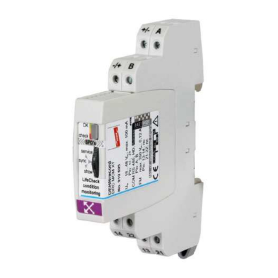
SPDs with LifeCheck symbol don’t have to be removed for function testing. They can be tested during system operation (e.g. in the distribution cabinet). Figure 1 : DEHNrecord DRC MCM XT stationary monitoring device protected by ISO 16016 Page 6 of 49... -
Page 7: Lifecheck
Within this system, one device will be configurated as "master" and all others as "slaves". The "master" controls the monitoring of all DRC MCM XT devices connected to the same bus. For this purpose it protected by ISO 16016 Page 7 of 49 Date of issue: 10.03.10... - Page 8 PC or laptop, the following functions of this program can be applied: • Status indication chart of all DRC MCM XT monitoring devices connected at the RS485 bus of all protection modules assigned to a DRC MCM XT •...
- Page 9 DEHN + SÖHNE Operating Manual Status Display With Integraded Service Console Figure 3 : DRC MCM XT program Status Display with integrated Service Console protected by ISO 16016 Page 9 of 49 Date of issue: 10.03.10...
-
Page 10: Installation
® Framework 2.0 has already been installed. If not, the program will be downloaded from the Microsoft website. Afterwards, the DRC MCM XT status display will be installed. Note: Before installing the program, the driver delivered together with the required RS485 interface adapter should be installed. -
Page 11: Installing The .Net-Framework
4.2.2 Installing the DRC MCM XT status display with integrated service console Finally, the DRC MCM XT status display with integrated service console is installed. As soon as the window showing a security warning is opened, click the "Install" button to continue the procedure. -
Page 12: Operation Of "Status Display With Integrated Service Console
In the "Status Display" mode the program is operated as passive subscriber at the RS485 bus and is just monitoring the data communication of the DRC MCM XT monitoring devices -> "monitoring mode". protected by ISO 16016 Page 12 of 49... -
Page 13: Settings For The Status Display
6.1.1 Setting the communication interface In order to enable the program to determine the current state of the DRC MCM XT monitoring devices and the assigned surge protection modules for indication, the program has to listen in the data communication of the monitoring devices (via the RS485 bus) (thus the program is a passive bus subscriber). -
Page 14: Language Selection
The same COM port as determined before in the system control has to be selected (refer also to It has to be really ensured that: • the PC laptop is connected with the RS485 bus of DRC MCM XT via the installated RS485 interface adapter • the monitoring devices are activated and started ®... - Page 15 English by the texts in the language he prefers. The file "user_defined_language.txt" has the following structure: [user defined texts] DRC MCM XT Status Display=?1 DRC MCM XT Service Console=?2 Select COM port=?3 Please select COM port first=?4...
-
Page 16: Use Of Local Schemata (Locales) In Ms Windows
DEHN + SÖHNE Operating Manual Status Display With Integraded Service Console ® 6.1.3 Use of local schemata (locales) in MS Windows In the following a brief summary on the use of local schemata (locales) in MS ® ® Windows . A detailed help file is available in MS Windows Entering and display of foreign character sets ==================================== ®... -
Page 17: Entering The System Description
The texts are used both in the log and as a screen copy. For each of the maximum 15 monitoring devices of a DRC MCM XT a short description (e.g. place of installation) can be entered in the operating surface. Double-... - Page 18 DEHN + SÖHNE Operating Manual Status Display With Integraded Service Console For safety reasons entering of texts is blocked per default. Clicking the button "Modification approval" texts can be entered again or changed. After release the button colour shows RED and the button signals "Apply entries". After clicking the button "Apply entries"...
-
Page 19: Loading The Last Program Settings
6.4 Activating the log function The Status Display allows for the logging of the status change of all DRC MCM XT monitoring devices or of the assigned SPDs in a file on the PC. After clicking the "Log ON"... -
Page 20: Help Function
DEHN + SÖHNE Operating Manual Status Display With Integraded Service Console After closing the log function or the status display, this text file can be opened and printed with the according program (e.g. Editor Notepad, Wordpad, MS Word etc.) (see also 6.9) Note If beside the SPD status changes also the initial state of the system shall be logged, it is absolutely necessary to activate logging before the first clicking of the "Start"... -
Page 21: Exit Program
6.7.1 Starting status monitoring and status indication If the PC is connected to the RS485 bus correctly, the status monitoring and status indication can be started for all DRC MCM XT devices connected to the bus and of all ... - Page 22 DEHN + SÖHNE Operating Manual Status Display With Integraded Service Console For this "Monitoring" operation it is necessary that • exactly one monitoring device is active as "master" at the bus • all other monitoring devices work as "slave" The user is responsible for the setting of the respectively required operating state. During the background processing, the program is continuouly monitoring, •...
-
Page 23: Status Display
6.7.2 Status display The status display indicates the own operating state of each correctly working DRC MCM XT and the operating state of the Blitzductors assigned to it. 6.7.2.1 Status of DRC MCM XT monitoring devices The following information will be indicated for each monitoring device: •... -
Page 24: Status Of The Protective Devices (Blitzductors )
DEHN + SÖHNE Operating Manual Status Display With Integraded Service Console • Function as bus device (master or slave) See 6.7.2.2. Function as bus device Overall status of all protective devices in this group all OK one or more SPDs to be replaced device in starting sequence (not yet testing) Current process: T = Testing of protective devices... -
Page 25: Resetting The Operating State Indication
DEHN + SÖHNE Operating Manual Status Display With Integraded Service Console 6.7.3 Resetting the operating state indication Clicking the "Reset display" button, the status display will be reset and all existing operating states will be deleted (corresponds to the operating state before clicking the start button, status = undefined). -
Page 26: Printing The Current System Status (Test Report)
DEHN + SÖHNE Operating Manual Status Display With Integraded Service Console 6.8 Printing the current system status (test report) Clicking the "Print" button, a window is opened for printing. Here, the printer can be selected for indicating the current operating state of the status display. This function can be used for compiling a test report. - Page 27 (supplementary information – e.g. inspector) Starting time (logging) Status changes consisting of : Bus address of DRC MCM XT + new operating state with date/time Initial status when starting the logging protected by ISO 16016 Page 27 of 49...
-
Page 28: Changeover To Service Console
Blitzductors assigned will be be reset to "undefined" (- -). If there is no updated test result available for a DRC MCM XT device (e.g. because a device is started or the connection was interrupted) the processing state will be marked with "!"... -
Page 29: Service Console
To ensure that the user is setting the system into "Service mode" a window is opened where the user has to confirm that for the service console operation: • the DRC MCM XT, which was configurated as 'master' has been reset to the 'slave mode' •... - Page 30 DEHN + SÖHNE Operating Manual Status Display With Integraded Service Console During the background processing, the program is continuouly monitoring that no "master" is active at the bus. Whenever an active "master" is detected, a display window opens informing the user that the program will return to the Status Display in order to avoid faulty states.
-
Page 31: Settings Of The Service Console
• the 'service mode' has to be quit on all DRC MCM XT devices • one of the DRC MCM XT devices has to be reset to the 'master mode' After finally clicking the "OK" button, the Service Console closes and the Status Display opens. - Page 32 Connection being successful the number of the Blitzductors configurated for this DRC MCM XT is indicated. In case of fault a warning is shown in the main window and an additional window displays possible reasons of fault (see top right figure).
-
Page 33: General Operating Procedure
DEHN + SÖHNE Operating Manual Status Display With Integraded Service Console 7.2 General operating procedure The general procedure of performing a test command will be described in the following. A detailled description of the available test commands can be taken from 7.3. - Page 34 DEHN + SÖHNE Operating Manual Status Display With Integraded Service Console If the test command requires another parameter it will be specified in the index line. This parameter now can be selected accordingly. Click the "Send command" button to perform the test command. protected by ISO 16016 Page 34 of 49 Date of issue: 10.03.10...
- Page 35 Only after arrival of the answer on DRC MCM XT monitoring device or in case of fault after expiration of the answer control time, this input blocking is released again.
-
Page 36: Function Of The Service Console
7.3.1 Inquiring the version number of a DRC MCM XT monitoring device Call of the test command "Software version of DRC MCM XT" is performed without parameters by clicking the "Send command" button after selecting the command. The service console shows the hardware version number as well as the software version number and the date of issue. -
Page 37: General Test Of All Protection Modules Assigned To A Drc Mcm Xt
7.3.2 General test of all protection modules assigned to a DRC MCM XT Call of the test command "Check all SPDs of DRC MCM XT" is performed without parameters by clicking the "Send command" button after selecting the command. The... -
Page 38: Single Test Of A Protection Module
7.3.3 Single test of a protection module Call of the test command "Check an individual SPD of DRC MCM XT" is performed with parameter by clicking the "Send command" button after selecting the command. -
Page 39: Determining The Current Number Of A Protection Module
"no SPD found". Note: When determining a protection module there may be no other protection module within a circle of approx. 25 cm around the DRC MCM XT, as otherwise the protection module can not be clearly identified. protected by ISO 16016 Page 39 of 49 Date of issue: 10.03.10... -
Page 40: Programming A Protection Module
The Blitzductors are programmed by means of the test command "Program an individual SPD of DRC MCM XT". The call is performed with parameters by clicking the "Send command" button after selecting the command. The parameter to be selected is the serial number of the protection module to be programmed. - Page 41 DEHN + SÖHNE Operating Manual Status Display With Integraded Service Console If programming was successful an additional window opens which requests for input of the SPD labelling (which contains the now valid bus address and the current SPD number). By marking the check box ("Do not show this window again") the reference display window will not be opened any more before the program is stated again.
-
Page 42: Programming All Portection Modules Of A Drc Mcm Xt
"Cancel" button. The following describes the different steps by means of the corresponding screenshots. Call of the test command "Program all SPDs of a DRC MCM XT" is performed without parameters after selecting the command. - Page 43 DEHN + SÖHNE Operating Manual Status Display With Integraded Service Console After setting the bus address of the requested DRC MCM XT monitoring device you will be asked to click the "Continue" button. Clicking the "Continue" button the number of the SPD to be programmed next will be set, and you will be asked to place an "unprogrammed"...
- Page 44 DEHN + SÖHNE Operating Manual Status Display With Integraded Service Console After successful programming (as described in 7.3.5) a reference display window opens requesting to completely snap on the SPD and to label it at once. By clicking the "Continue" button the same procedure can be started with the next SPD. protected by ISO 16016 Page 44 of 49 Date of issue: 10.03.10...
- Page 45 DEHN + SÖHNE Operating Manual Status Display With Integraded Service Console In case of incorrect programming the process for the same "SPD number" can just be repeated by clicking the "Send command" button as often as necessary. Preferably the same SPD first should be used again and only if this attempt fails a new SPD shall be inserted.
-
Page 46: Resetting A Protection Module
The test command "Reset individual SPD to its original state" allows to reset Blitzductors already assigned to a DRC MCM XT monitoring device into the as- delivered status (reprogramming). The device is called by entering parameters and clicking the "Send command" button after selecting the command. - Page 47 DEHN + SÖHNE Operating Manual Status Display With Integraded Service Console If the resetting process was successful, a reference display window opens, requesting to remove the 'old' SPD labelling (which includes the no longer valid bus address and the previous running SPD number. In case of a resetting failure, a further attempt should be made as probably the RFID field was sporadically interferred.
- Page 48 DEHN + SÖHNE Operating Manual Status Display With Integraded Service Console protected by ISO 16016 Page 48 of 49 Date of issue: 10.03.10...
- Page 49 DEHN + SÖHNE Operating Manual Status Display With Integraded Service Console Notes protected by ISO 16016 Page 49 of 49 Date of issue: 10.03.10...
- Page 50 Lightning Protection Surge Protection Safety Equipment DEHN + SÖHNE Hans-Dehn-Straße 1 Postfach 1640 92306 Neumarkt Germany Tel. +49 9181 906 462 Fax +49 9181 906 444 www.dehn.de export@dehn.de...
Need help?
Do you have a question about the DRC MCM XT and is the answer not in the manual?
Questions and answers