Table of Contents
Advertisement
Quick Links
Advertisement
Table of Contents

Summary of Contents for MegaTec NetFeeler Mini
- Page 1 User Manual NetFeeler Mini...
-
Page 3: Table Of Contents
4. Application............4 4.1. Connect to iCAMView Webcam Server ...... 4 5. Settings .............. 5 5.1. How to set RFID on Netfeeler Mini ......6 5.2. How to set Wireless Smoke/Gas Sensors....8 5.3. How to set Wireless D/W Sensor.......11 5.4. -
Page 5: Introduction
4. Wireless Glass-Break sensor 5. Wireless InfraRed Beam detector 6. Wireless PIR sensor When an event occurs, NetFeeler Mini alarm will buzz. It can also be configured to simultaneously send an email thru iCAMView PRO (Model: iCV-32). When connected to iCAMView PRO, use can use it to monitor the environment status via the internet using a standard browser. -
Page 6: Features
2. Features 2. Features Œ Able to measure variations in temperature, humidity and presence of water. • Built-in radio frequency (“RF”) receiver. Ž Support up to 7 individually ID’d wireless Door / Window sensor to detect unauthorized access. • Support Wireless Smoke or Gas sensor to trigger alarm and send notification. -
Page 7: Specifications
Accuracy Response Time 10 Sec. Temperature -40℃ to +75℃ (-40℉ to +75℉) Range Temperature Specification Detection Range -40℃ to +70℃ ±3℃ Accuracy Response Time 10 Sec. RF Specification Detection Range 6~10 meter visible range Frequency 315MHZ Sensitivity -105dB NetFeeler Mini... -
Page 8: Application
4.1. Connect to iCAMView Webcam Server Œ Monitor environment data via a standard web browser • Send Email when an event occurs. Ž Powered either directly from iCAMView or use a 5V power input. Fig.1 Conect to Netfeeler Mini NetFeeler Mini... -
Page 9: Settings
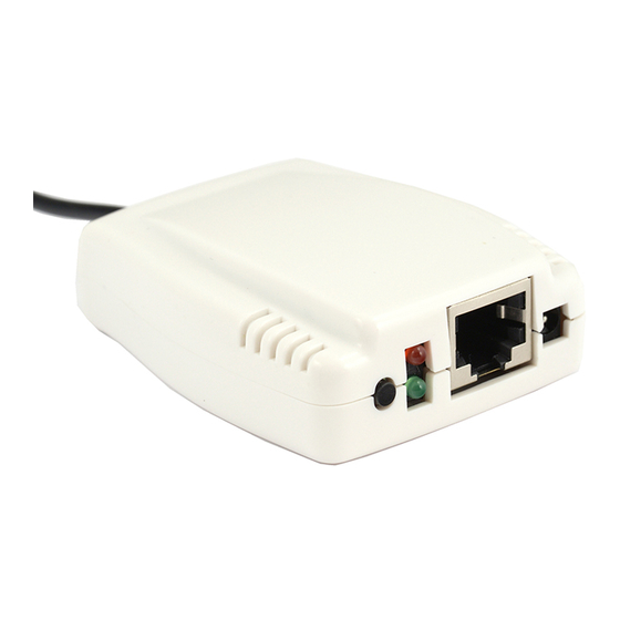
Yellow LED Alarm Indicator Reset button To turn off alarm Power supply 5VDC or thru iCAMView RS232 port To connect to iCAMView PRO (Model: iCV-32) RFID Switch Used for pairing NetFeeler Mini with wireless devices (located at bottom) NetFeeler Mini... -
Page 10: How To Set Rfid On Netfeeler Mini
Settings 5.1. How to set RFID on Netfeeler Mini Œ Set RFID switch 1 and 2: “on” • Set RFID switch 3 to 8: “off“ Once set, the combinations will be used to pair other wireless device to NetFeeler Mini. - Page 11 Settings NetFeeler Mini has 9 different slots to identifying wireless device. Each is allocated a default binary or DIP equivalent settings. Only the binary reference for smoke and gas sensors are fixed. The binary reference from 1 to 7 are interchangeable.
-
Page 12: How To Set Wireless Smoke/Gas Sensors
When a leakage is detected, the gas sensor will buzz. An external 9~12V power input is required for gas sensor. To setup: 1. Open the cover (top part) of Wireless Smoke/Gas sensor to reveal two sets of DIP switches (see Fig. 3) NetFeeler Mini... - Page 13 Settings 2. The bottom (longer) DIP switch show pins A0 to A7. This set of DIP is used to pair the wireless sensor with Netfeeler Mini. Set these DIP as follows: Œ DIP A0 to A1: set to “on” Connect pins from row H with middle pin using a jumper (see illustration below).
- Page 14 Settings 3. The second set of DIP switch show 4 sets of pins. This set allow Netfeeler Mini to identify the type of sensor. Sensor Type DIP settings 0010 Smoke 1010 Fig.4 Wireless Smoke /Gas Sensor default Code(Top-Right) NetFeeler Mini...
-
Page 15: How To Set Wireless D/W Sensor
Use the Wireless Door / Window sensor to secure the front door, balcony entrance or window. When there is an intrusion, the sensor will signal NetFeeler Mini to sound an alarm. To setup: 1. Open the Door / Window sensor casing (use a flat head screwdriver and pry it open from the bottom). - Page 16 DIPs D0 to D3 DIPs A7 to A0 Ignore the last DIP Fig.5 Wireless Door / Window sensor DIP Switch Sensor Type DIP settings Door / Window 1011 Fig. 6 Wireless Door / Window sensor (D0 to D3) NetFeeler Mini...
-
Page 17: How To Set Glass Sensor
/ door. Install the sensor on the wall or ceiling next to the glass window / door. If the glass is broken, NetFeeler Mini will sound an alarm. Note: An external 9~12V power input is required. - Page 18 Fig. 7. 3. Set DIPs A0 to A7 the same as the wireless smoke / gas sensor in section 5.2 above. Fig.7 Wireless glass sensor DIP switch Sensor Type DIP settings Glass 0101 Fig.8 Wireless glass sensor DIP setting NetFeeler Mini...
- Page 19 If the InfraRed Beam is interrupted, the detector will sound an alarm and send a signal to NetFeeler Mini. Note: An external 9~12V power input is required. To setup: 1.
- Page 20 Settings Fig.9 InfraRed Beam detector DIP Switch Sensor Type DIP settings InfraRed Beam detector 0011 Fig.10 InfraRed Beam detector default Code(Right DIP Switch) NetFeeler Mini...
- Page 21 PIR sensor is normally installed in important rooms, on walls, ceiling or passageway. PIR will be triggered when there is an unauthorized access and a signal will be sent to NetFeeler Mini. To setup the device; 1. Open the cover by removing the screw located at the bottom of the unit.
- Page 22 Section 5.2 “+ + - - - - - -“ 3. Set the next for DIPs 13 to 10 (from RIGHT to LEFT) “+ - - +” Fig.11 PIR DIP switch Sensor Type DIP settings 1001 Fig. 12 PIR code (from RIGHT to LEFT DIP Switch) NetFeeler Mini...
Need help?
Do you have a question about the NetFeeler Mini and is the answer not in the manual?
Questions and answers