Advertisement
Quick Links
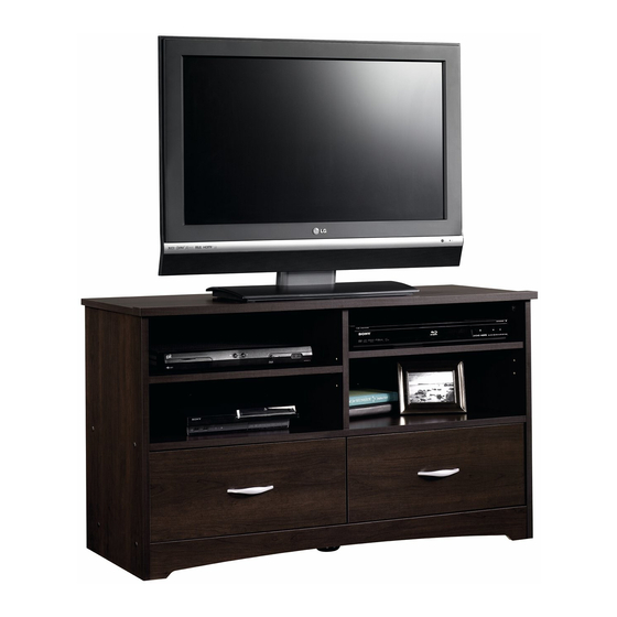
413045
TV Stand
PLEASE CONTACT US
BEFORE RETURNING
YOUR UNIT TO THE STORE
1-800-523-3987
www.sauder.com
NOTE: THIS INSTRUCTION BOOKLET CONTAINS
IMPORTANT SAFETY INFORMATION.
PLEASE READ AND KEEP FOR FUTURE REFERENCE.
English .................... Page 1-18
Français ...............Pages 19-21
Made in the USA
Espanol .............Páginas 22-24
Archbold, OH
Lot #: 352976
Date Purchased: ____________________
05 / 08 / 13
Advertisement

Related Manuals for Sauder 413045


Summary of Contents for Sauder 413045
- Page 1 413045 TV Stand NOTE: THIS INSTRUCTION BOOKLET CONTAINS IMPORTANT SAFETY INFORMATION. PLEASE CONTACT US PLEASE READ AND KEEP FOR FUTURE REFERENCE. BEFORE RETURNING English ....Page 1-18 YOUR UNIT TO THE STORE Français ....Pages 19-21 Made in the USA 1-800-523-3987 Espanol .....Páginas 22-24...
- Page 2 • Check the size and weight of your TV. Compare it to the diagram below – before you begin assembly! • This Sauder unit is designed for use with televisions weighing less than 95 pounds. Never use with a TV that weighs more.
-
Page 3: Part Identification
RIGHT END SHELF RIGHT DRAWER SIDE LEFT END ADJUSTABLE SHELF LEFT DRAWER SIDE LARGE UPRIGHT BACK D967 DRAWER BOTTOM SMALL UPRIGHT RIGHT DRAWER FRONT SKIRT LEFT DRAWER FRONT STOP MOLDING BOTTOM DRAWER BACK D967 D967 413045 www.sauder.com/services Page 3... -
Page 4: Hardware Identification
EE SILVER 3/4” MACHINE SCREW - 4 BROWN 7/16" LARGE HEAD SCREW - 16 GOLD 5/16" FLAT HEAD SCREW - 16 NAIL - 42 Screws are shown actual size. You may receive extra hardware with your unit. Page 4 www.sauder.com/services 413045... - Page 5 Push twelve HIDDEN CAMS (R2) into the ENDS (A and B), UPRIGHTS (C and D), and TOP (E). Then, insert the metal end of a eight CAM DOWELS (S2) into the HIDDEN CAMS in the ENDS and UPRIGHTS. 413045 www.sauder.com/services...
- Page 6 If the STOP MOLDING (Q) has an unfi nished surface, it should be positioned here. Turn four CAM SCREWS (T2) into the STOP MOLDING (Q). Fasten the STOP MOLDING (Q) to the TOP (E). Tighten four HIDDEN CAMS. Page 6 www.sauder.com/services 413045...
- Page 7 GOLD 5/16” FLAT HEAD SCREW (8 used in this step) Fasten the CABINET RIGHTS (35DA) and CABINET LEFTS (35DB) to the ENDS (A and B) and SMALL UPRIGHT (D). Use eight GOLD 5/16" FLAT HEAD SCREWS (GG). 413045 www.sauder.com/services Page 7...
- Page 8 Tighten Arrow Risk of damage or injury. Hidden Cams must be completely Arrow Maximum tightened. Hidden 210 degrees Cams that are not completely tightened Minimum may loosen, and parts 190 degrees may separate. To completely tighten: Page 8 www.sauder.com/services 413045...
- Page 9 Arrow 210 degrees Minimum 190 degrees Fasten the SHELF (G) to the LARGE UPRIGHT (C). Use two BLACK 1-7/8" FLAT HEAD SCREWS (CC). Fasten the SMALL UPRIGHT (D) to the SHELF (G). Tighten two HIDDEN CAMS. 413045 www.sauder.com/services Page 9...
- Page 10 BLACK 1-7/8" FLAT HEAD SCREW (2 used in this step) (4 used) Fasten the BOTTOMS (F) to the SMALL UPRIGHT (D). Use two BLACK 1-7/8" FLAT HEAD SCREWS (CC). Insert four METAL PINS (Z) into the BOTTOMS (F). Page 10 www.sauder.com/services 413045...
- Page 11 Fasten the ENDS (A and B) to the BOTTOMS (F) and SHELF (G). Use eight BLACK 1-7/8" FLAT HEAD SCREWS (CC). NOTE: Be sure the METAL PINS in the BOTTOMS (F) insert into the holes in the ENDS (A and B). 413045 www.sauder.com/services...
- Page 12 NOTE: Be sure the edges of the ANGLE BRACKETS are even with the edges of the BOTTOM and SKIRT. Fasten the SKIRT (P) to the ENDS (A and B) and BOTTOM (F). Use six BROWN 7/16" LARGE HEAD SCREWS (FF). Page 12 www.sauder.com/services 413045...
- Page 13 NOTE: Be sure to tap NAILS into the holes that line up over the UPRIGHTS (C and D) and SHELF (G). NOTE: Perforations have been provided for access through the BACK. Carefully cut out the holes needed. Push the FOOT (X) into the hole in the BOTTOM (F). 413045 www.sauder.com/services Page 13...
- Page 14 Fasten the DRAWER SIDES (D40 and D41) to the DRAWER BACK (D69). Use four BLACK 1-9/16" FLAT HEAD SCREWS (DD). Slide the DRAWER BOTTOM (D967) into the grooves in the DRAWER SIDES (D40 and D41) and DRAWER BACK (D69). Repeat this step for the other drawer. Page 14 www.sauder.com/services 413045...
- Page 15 Pull the DRAWER FRONT BRACKETS (V) apart and slide them into the grooves in the DRAWER SIDES (D40 and D41). Fasten the RIGHT DRAWER FRONT (J) to the DRAWER FRONT BRACKETS (V). Use two BROWN 7/16" LARGE HEAD SCREWS (FF). Repeat this step for the other drawer using the LEFT DRAWER FRONT (K). 413045 www.sauder.com/services Page 15...
- Page 16 Fasten the DRAWER RIGHT (35DC) and DRAWER LEFT (35DD) to the DRAWER SIDES (D40 and D41). Use four GOLD 5/16" FLAT HEAD SCREWS (GG). Fasten the PULL (W) to the RIGHT DRAWER FRONT (J). Use two SILVER 3/4" MACHINE SCREWS (EE). Repeat this step for the other drawer. Page 16 www.sauder.com/services 413045...
- Page 17 Push the RUBBER SLEEVES (AA) over the remaining METAL PINS (Z). Insert the METAL PINS into the hole locations of your choice in the ENDS (A and B) and LARGE UPRIGHT (C). Set the ADJUSTABLE SHELVES (H) onto the METAL PINS. 413045 www.sauder.com/services...
- Page 18 Center a SCREW COVER (Y) over the head of each visible SCREW in the ENDS (A and B) and press firmly. NOTE: Please read the back pages of the instruction booklet for important safety information. This completes assembly. Clean with your favorite furniture polish or a damp cloth. Wipe dry. Page 18 www.sauder.com/services 413045...
-
Page 19: Liste De Pièces
DD VIS NOIRE TÊTE PLATE 40 mm ..8 et conserver le livret MOULURE DE BUTÉE ....1 pour future référence. VIS ARGENTÉE À Pour contacter Sauder MÉTAUX 19 mm ......4 en ce qui concerne cet VIS MARRON TÊTE 35DA ÉLÉMENT DROITE ......2 élément, faire référence... - Page 20 Utiliser deux VIS NOIRES TÊTE PLATE 48 mm (CC). diagramme ci-dessous avant de commencer l'assemblage ! Fixer le PETIT MONTANT (D) à la TABLETTE (G). • Cette unité Sauder est conçue pour les téléviseurs Serrer deux EXCENTRIQUES ESCAMOTABLES. pesant moins de 43 kg. Ne jamais utiliser avec des téléviseurs plus lourds.
- Page 21 GAUCHE (35DD) aux CÔTÉS DE TIROIR (D40 et D41). Utiliser quatre VIS DORÉES TÊTE PLATE 8 mm (GG). Fixer la POIGNÉE (W) au DEVANT DE TIROIR DROIT (J). Utiliser deux VIS ARGENTÉES À MÉTAUX 19 mm (EE). Répéter cette étape pour l'autre tiroir. 413045 www.sauder.com/services Page 21...
-
Page 22: Lista De Partes
Si necesita ponerse TORNILLO PLATEADO en contacto con PARA METAL de 19 mm ....4 35DA GABINETE DERECHO ....2 Sauder en cuanto a TORNILLO MARRÓN DE esta unidad, refi érase 35DB GABINETE IZQUIERDO....2 CABEZA GRANDE de 11 mm ..16 al número de lote y 35DC CAJÓN DERECHO ......2... - Page 23 Fije el PARAL GRANDE (C) al PANEL SUPERIOR (E). Apriete dos EXCÉNTRICOS ESCONDIDOS. • Esta unidad Sauder está diseñada para ser usada con televisores cuyo peso sea inferior a 43 Kg. Nunca la use para un televisor de mayor peso.
- Page 24 DORADOS DE CABEZA PERDIDA de 8 mm (GG). Fije el TIRADOR (W) a la CARA DERECHA DE CAJÓN (J). Utilice dos TORNILLOS PLATEADOS PARA METAL de 19 mm (EE). Repita este paso para el otro cajón. Page 24 www.sauder.com/services 413045...
- Page 25 équipé. • Blessure physique. Le mobilier peut être mobilier. très lourd. • Ne pas pousser le mobilier, surtout sur la moquette. Se faire aider par une autre personne pour soulever l’élément et le mettre en place. 413045 www.sauder.com/services Page 25...
- Page 26 • Lesión física. El mobiliario puede ser • No empuje la unidad, especialmente muy pesado. sobre un piso alfombrado. Pide la ayuda de otra persona en levantar la unidad y colocarla en lugar. Page 26 www.sauder.com/services 413045...
-
Page 27: Year Limited Warranty
4. La présente garantie ne s’applique qu’aux défauts garantis qui se produisent des composantes de mobilier Sauder. Le mot « défaut », tel qu’il est utilisé sous pour la première fois et qui sont signalés à Sauder dans les limites de ouverture les termes de la présente garantie, comprend les imperfections des pièces qui... - Page 28 Archbold, Ohio, where it all began. Certifi cate of Conformity The Sauder name on the box ensures that 1. This certifi cate applies to the Sauder Woodworking Product indentifi ed by this Instruction Book. the item you have purchased is made with 2.
Need help?
Do you have a question about the 413045 and is the answer not in the manual?
Questions and answers