Table of Contents
Advertisement
Quick Links
Advertisement
Table of Contents

Related Manuals for ZCS CONNEXT

Summary of Contents for ZCS CONNEXT
- Page 1 ACCESSORY CONNEXT...
- Page 2 Via Lungarno, 248 - 52028 Terranuova Bracciolini - Arezzo, Italy tel. +39 055 91971 - fax. +39 055 9197515 innovation@zcscompany.com - zcs@pec.it - zcsazzurro.com Reg. Pile IT12110P00002965 - Share Capital € 100,000.00 fully paid up AR Company Reg. no. 03225010481 - REA AR no. 94189...
- Page 3 (including the software, etc.) may be copied, reproduced or distributed in any form or by any means without the permission of Zucchetti Centro Sistemi S.p.A. All rights reserved. ZCS reserves the right to final interpretation. This manual is subject to change based on feedback from users, installers or customers.
-
Page 4: Table Of Contents
4.3.4. Connecting to Azzurro single-phase photovoltaic inverters ............25 4.3.5. Connecting to Azzurro three-phase photovoltaic inverters ............26 4.4. Connecting to current sensors or meter ................... 27 Connext User Manual Rev. 1.2 07/06/2021 3/50 Identification: MD-AL-GI-00 Rev. 1.0 07.06.21 - Application: GID... - Page 5 Technical datasheet ........................47 Maintenance ........................... 48 8.1. Troubleshooting ........................48 8.2. Maintenance ..........................48 Dismantling and disposal ........................ 49 Warranty terms and conditions ....................50 Connext User Manual Rev. 1.2 07/06/2021 4/50 Identification: MD-AL-GI-00 Rev. 1.0 07.06.21 - Application: GID...
- Page 6 The manual is also intended for end users who can find useful information on how to manage their installation via the Connext system. Symbols used This manual provides information for safe operation and uses certain symbols to ensure the safety of personnel and materials, and for efficient use of the equipment during normal operation.
- Page 7 Attention Note: provides important tips on correct and optimal operation of the product Note Connext User Manual Rev. 1.2 07/06/2021 6/50 Identification: MD-AL-GI-00 Rev. 1.0 07.06.21 - Application: GID...
-
Page 8: Preliminary Safety Instructions
Install and start the system according to the following instructions. Choose a suitable location for installation of the electrical equipment. Make sure there is sufficient space to accommodate future maintenance work. Connext User Manual Rev. 1.2 07/06/2021 7/50 Identification: MD-AL-GI-00... - Page 9 Warning Do not remove the information label or to tamper with the system. Otherwise, ZCS will not provide any warranty or assistance. Note Connext User Manual Rev. 1.2 07/06/2021...
-
Page 10: Symbols And Icons
Before installation, it is important to read and understand the contents of the symbols. Complies with the European Standards (CE) Ground connection point Table 1 – Symbols on the System Connext User Manual Rev. 1.2 07/06/2021 9/50 Identification: MD-AL-GI-00 Rev. 1.0 07.06.21 - Application: GID... -
Page 11: Labels
Main Document Only. 1.3. Labels Figure 2 - Labels on the System Connext User Manual Rev. 1.2 07/06/2021 10/50 Identification: MD-AL-GI-00 Rev. 1.0 07.06.21 - Application: GID... -
Page 12: Product Features
2. Product features 2.1. Product presentation The “Connext” control system is able to communicate with Azzurro electric vehicle charging stations and Azzurro photovoltaic inverters. It can also measure energy consumption, monitor systems and safety limits and control domestic loads through the use of accessory sensors and programmable contacts. -
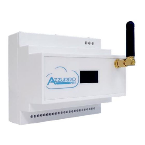
Page 13: Product Overview
Overall dimensions: H × W × D = 105 mm x 85 mm (with antenna installed) x 89 mm. 2.2. Product overview “Connext” can be installed on DIN bar (8 modules) and powered by a 230V AC mains power supply. It can be connected to Azzurro accessories, charging stations and inverters, as well as the necessary power supplies. - Page 14 (only for Ethernet models), a slot for a microSD card at the top (for data storage), a front graphic display and a front connection for the 4G (or Wi-Fi) communication antenna. Connext User Manual Rev. 1.2 07/06/2021 13/50 Identification: MD-AL-GI-00 Rev.
-
Page 15: 24-Pin Terminal Block
1 B sensor Earth connection 1 A sensor Table 2 – 24-pin terminal block pin-out The maximum acceptable cable cross-section for the terminals is 1mm Connext User Manual Rev. 1.2 07/06/2021 14/50 Identification: MD-AL-GI-00 Rev. 1.0 07.06.21 - Application: GID... -
Page 16: 3-Pin Terminal Block
2.2.4. Ethernet connector The Ethernet connector with two LEDs allows network connection only for models with Ethernet enabled. PLEASE ASK ZCS TO ENABLE THE PORT Connext User Manual Rev. 1.2 07/06/2021... -
Page 17: Installation
After removing the system from its packaging, check that the product is intact and complete. If any damage is found or components are missing, contact the supplier and transport company. Contents of the packaging Item Connext system Connext User Manual Rev. 1.2 07/06/2021 16/50 Identification: MD-AL-GI-00 Rev. 1.0 07.06.21 - Application: GID... -
Page 18: Installation Tools
3.2.1. Installation position Choose an appropriate installation location. Follow the requirements below to determine the installation position. The installation location chosen must allow easy access for normal operation and maintenance. Connext User Manual Rev. 1.2 07/06/2021 17/50 Identification: MD-AL-GI-00 Rev. 1.0 07.06.21 - Application: GID... -
Page 19: Materials And Cables
Main Document Only. For safety reasons, ZCS and/or its authorised partners may not perform repair/maintenance work or move the chargers from and to the ground if they are installed at a height of more than 180 cm. Stations installed at higher heights must be moved to the ground before they can be repaired or serviced. -
Page 20: Electrical Connections
Attention 4.1. Connecting the AC power cables Connect the Connext system to the AC power supply network or to the mains using the AC power cables. Context All AC power cables used for the inverter must be three-pole outdoor cables. For easier installation, use flexible cables. -
Page 21: Connecting To Azzurro Ev Charging Stations
4.2. Connecting to Azzurro EV charging stations Up to 8 Azzurro EV charging stations can be connected in cascade. Connect the Connext system to the first EV charging station according to the instructions given here. 1) Connect the 8-pin cable to the ports indicated as CAN port in relative Figure using a RJ45 connector. - Page 22 Figure 9 - RJ45 connector pinout 2) Remove a suitable length of the protective sleeve, as shown in figure (A: 80~100 mm B: 6~8 mm). Figure 10 – Preparing the CAN bus cables Connext User Manual Rev. 1.2 07/06/2021 21/50 Identification: MD-AL-GI-00...
-
Page 23: Connecting To Azzurro Photovoltaic Or Storage Inverters
Up to 8 Azzurro photovoltaic or storage inverters can be connected in cascade. Connect the Connext system to the first inverter according to the instructions given here. To connect to hybrid, storage or photovoltaic inverters, follow the instructions in the sections below. -
Page 24: Connecting To 3000Sp Inverter
To connect the RS485 port to 3000SP inverters, follow these instructions. 1) Remove a suitable length of the protective sleeve, as shown in the figure (A: 80~100 mm B: 6~8 mm). Connext User Manual Rev. 1.2 07/06/2021 23/50 Identification: MD-AL-GI-00... -
Page 25: Connecting To Azzurro 3-Phase Hybrid Inverters
Table 9 - RS485 connections to 3000SP inverter 4.3.3. Connecting to Azzurro 3-phase hybrid inverters To connect the RS485 port to HYD-5000/6000/8000/10000/15000/20000 inverters, follow these instructions. Connext User Manual Rev. 1.2 07/06/2021 24/50 Identification: MD-AL-GI-00 Rev. 1.0 07.06.21 - Application: GID... -
Page 26: Connecting To Azzurro Single-Phase Photovoltaic Inverters
Table 10 – RS485 connections on 3-phase hybrid inverter 4.3.4. Connecting to Azzurro single-phase photovoltaic inverters To connect the RS485 port to Azzurro single-phase photovoltaic inverters, follow these instructions. Connext User Manual Rev. 1.2 07/06/2021 25/50 Identification: MD-AL-GI-00 Rev. 1.0 07.06.21 - Application: GID... -
Page 27: Connecting To Azzurro Three-Phase Photovoltaic Inverters
4.3.5. Connecting to Azzurro three-phase photovoltaic inverters To connect the RS485 port to Azzurro three-phase photovoltaic inverters, follow these instructions. 1) Use a RJ45 connector to connect one of the two RS485 ports on the inverter-side. Connext User Manual Rev. 1.2 07/06/2021 26/50 Identification: MD-AL-GI-00 Rev. -
Page 28: Connecting To Current Sensors Or Meter
(ZSM-ACC-TA). The sensor must be placed directly on the output of the photovoltaic inverter and connected to the Connext system via pins 21 and 22 of the 24-pin terminal block, as shown below. Connext User Manual Rev. -
Page 29: Sensor For Measuring Three-Phase Photovoltaic Production
The sensor must be placed directly on the output of the photovoltaic inverter and connected to the Connext system via pins 21 and 22 of the 24-pin terminal block, as shown below. To ensure correct calculation of the total power produced, when configuring the system on the APP, specify that the measurement is made in three-phase. -
Page 30: Sensor For Measuring 1-Phase Grid Exchanges
(ZSM-ACC-TA). The sensor must be placed directly on the output of the exchange meter and connected to the Connext system via pins 23 and 24 of the 24-pin terminal block, as indicated below. Sensor cable... -
Page 31: Meter For Measuring Grid Exchanges (Three-Phase System)
(ZSM-METER-DTSU). The meter must be placed directly on the output of the exchange energy meter and connected to the Connext system via port RS485, as indicated below. Figure 23 – Meter connections... -
Page 32: Initial System Configuration
The first account that registers the “Connext” system is the “Owner” 1. Create an account on the Azzurro Monitoring app and log in. 2. Power up the Connext system and wait until it is connected. The ☼ symbol represents the photovoltaic production, while the electrical socket represents exchanges with the grid. - Page 33 Main Document Only. 3. From the home page of the Azzurro App, click the “+” symbol. Connext User Manual Rev. 1.2 07/06/2021 32/50 Identification: MD-AL-GI-00 Rev. 1.0 07.06.21 - Application: GID...
- Page 34 Main Document Only. 4. When the Connext system is connected, select “Enter serial number.” Choose to scan the QRcode found on the device or manually enter the serial number in the form of CA020490200005. Connext User Manual Rev. 1.2 07/06/2021...
- Page 35 Main Document Only. 5. The initial configuration screen appears when the serial number is recognised. Connext User Manual Rev. 1.2 07/06/2021 34/50 Identification: MD-AL-GI-00 Rev. 1.0 07.06.21 - Application: GID...
- Page 36 Main Document Only. 6. In the owner registration screen enter the email addresses that have the ability to edit the system information, referred to as “Administrator” accounts. Connext User Manual Rev. 1.2 07/06/2021 35/50 Identification: MD-AL-GI-00 Rev. 1.0 07.06.21 - Application: GID...
- Page 37 Administrator account choice Change system power Add devices Change charging strategy (EVC) System monitoring 7. The Connext registration procedure on the app is the same, only the display of the device's registration page changes. Connext User Manual Rev. 1.2 07/06/2021 36/50 Identification: MD-AL-GI-00 Rev.
- Page 38 8. Click on “Go” to proceed with registration of the devices 9. Click on "Inverter +" to add the inverter and scan the barcode. The inverter's barcode is found on the side label. Connext User Manual Rev. 1.2 07/06/2021 37/50 Identification: MD-AL-GI-00 Rev.
- Page 39 Main Document Only. 10. Register the inverter by choosing the model (e.g. hybrid inverter) and address (e.g. 1) Connext User Manual Rev. 1.2 07/06/2021 38/50 Identification: MD-AL-GI-00 Rev. 1.0 07.06.21 - Application: GID...
- Page 40 Main Document Only. 11. Home page screen with hybrid inverter Connext User Manual Rev. 1.2 07/06/2021 39/50 Identification: MD-AL-GI-00 Rev. 1.0 07.06.21 - Application: GID...
- Page 41 8. 13. To add a charging station, click on “EVCharge +” and scan the barcode. The barcode can be found on the side label of the charging station. Connext User Manual Rev. 1.2 07/06/2021 40/50 Identification: MD-AL-GI-00 Rev.
- Page 42 Main Document Only. When a device's name is required, choose any name you like (e.g. "hybrid inverter") 14. If the photovoltaic inverter is from another brand, select “No ZCS devices” Connext User Manual Rev. 1.2 07/06/2021 41/50 Identification: MD-AL-GI-00 Rev. 1.0 07.06.21 - Application: GID...
- Page 43 15. Once all the devices have been registered, their details can be viewed by clicking on each of them individually. The drop-down menu in the top right-hand corner shows “General System” and the name of the Connext system selected in point 5 (e.g. Test ZCS) Connext User Manual Rev. 1.2 07/06/2021...
- Page 44 Keys to START and STOP the charging remotely IDLE: station in standby - CHARGING: charging - PARKING: the charging is completed, but the gun is still inserted - ERROR: there is a problem with the charging station. Connext User Manual Rev. 1.2 07/06/2021 43/50 Identification: MD-AL-GI-00 Rev.
- Page 45 Main Document Only. Connext User Manual Rev. 1.2 07/06/2021 44/50 Identification: MD-AL-GI-00 Rev. 1.0 07.06.21 - Application: GID...
- Page 46 1.8 kW which will remain until the photovoltaic production is greater than 500W. Below 500W of production, the wallbox will stop charging the vehicle. Connext User Manual Rev. 1.2 07/06/2021 45/50 Identification: MD-AL-GI-00 Rev.
-
Page 47: Access For Maintenance Only
1) Check the connections to the various elements of the system (EV charger, inverter, metre, sensors, etc.). 2) Make sure that the power cables of the Connext system in the 3-pin terminal block are NOT connected/powered. The L and N power cables disconnected from the system MUST •... -
Page 48: Technical Datasheet
Main Document Only. 7. Technical datasheet Connext User Manual Rev. 1.2 07/06/2021 47/50 Identification: MD-AL-GI-00 Rev. 1.0 07.06.21 - Application: GID... -
Page 49: Maintenance
Follow the maintenance procedure and contact the supplier. Visit the website www.zcsazzurro.com or call the toll free number 800 72 74 64. 8.2. Maintenance Connext systems generally do not require daily or routine maintenance. Connext User Manual Rev. 1.2 07/06/2021 48/50 Identification: MD-AL-GI-00... -
Page 50: Dismantling And Disposal
With your cooperation in the correct disposal of this product, you contribute to the reuse, recycling and recovery of the product, and to the protection of our environment. Connext User Manual Rev. 1.2 07/06/2021 49/50 Identification: MD-AL-GI-00 Rev. -
Page 51: Warranty Terms And Conditions
Main Document Only. 10. Warranty terms and conditions To view the “Warranty Terms and Conditions” offered by ZCS Azzurro, please refer to the documentation inside the product box and on the website www.zcsazzurro.com. Connext User Manual Rev. 1.2 07/06/2021 50/50 Identification: MD-AL-GI-00 Rev.
Need help?
Do you have a question about the CONNEXT and is the answer not in the manual?
Questions and answers