
Summary of Contents for CellSolutions 30
- Page 1 CellSolutions 30 Operator’s Manual Document Number: CS-OP-30US Rev. 07 Issue Date: July 24, 2020...
- Page 2 Copyright 2015 - CellSolutions, LLC. All rights reserved. No part of this manual or the described software may be copied, reproduced, translated or reduced to any electronic medium or machine-readable form without the prior written consent of CellSolutions, LLC., except that you may make one copy of the program and related files for back-up purposes.
-
Page 3: Table Of Contents
4.6 Specimen Application to Slide 4.7 Loading Slide into Staining Rack 4.8 Specimen Drying Section 5.0 Sample Preparation 5.1 Sample Collection 5.2 Sample Identification and Tracking 5.3 Sample Transfer 5.4 Centrifugation 5.5 Decanting CellSolutions 30 Operator’s Manual CS-OP-30US Rev. 07... - Page 4 6.7 System Shutdown 6-15 Section 7.0 Maintenance 7.1 Daily Maintenance 7.2 Weekly Maintenance 7.3 Semi-Annual Maintenance Section 8.0 Troubleshooting Appendix A Glossary of Terms Appendix B Glossary of Symbols Appendix C Microscope Slide Printer Index CellSolutions 30 Operator’s Manual CS-OP-30US Rev. 07...
-
Page 5: Preface
WARRANTY INFORMATION The CellSolutions 30 has a one-year warranty from the date of sale. For technical support or repair information contact your designated local representative or CellSolutions. -
Page 6: Section 1.0 Introduction
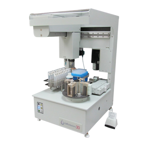
1.0 INTRODUCTION Intended Use The CellSolutions 30 automates certain steps in the process of preparing a microscope slide with a thin layer of cells for microscopic visual evaluation. The unit takes as input, preserved cell samples that have already been concentrated by centrifugation. The system then outputs optimized samples of approximately the same cellularity onto microscope slides that are ready for staining. - Page 7 Introduction 1.3.3 Electrical Hazards The CellSolutions 30 has 2 items that are separately plugged into an alternating current supply. The 2 items are a computer and the CellSolutions 30 Processing Platform. Each item operates on 100 to 240 volts and 50 to 60 Hz. Usual electrical precautions should be observed.
-
Page 8: Section 2.0 Specifications And Installation
2.0 SPECIFICATIONS AND INSTALLATION Equipment Specifications The system comes with a CellSolutions 30 processing platform, a computer and a Smart Card reader. A separate centrifuge and vortex mixer that is not provided with the system is needed to perform the overall process. The centrifuge and vortex mixer listed below are suggested units, however, others may be used as long as they can achieve the required G-forces and mixing requirements of the process. -
Page 9: Recommended Installation Space
3 kg (6 lbs) Recommended Installation Space In addition to the bench top space required to hold the CellSolutions 30 platform, space is also needed for the computer and for handling tubes, racks, and slides. Recommended Bench Space for CellSolutions 30:... -
Page 10: Installation And Setup
Installation and Setup The CellSolutions 30 should be placed on a sturdy and stable table that does not tilt or flex. The unit can be placed with the back toward a wall so long as there is at least 50 mm (2 inches) of space between the unit’s back and the wall. -
Page 11: Aligning Unit For Operation
After all the connections noted above are made, the computer and the processing platform can be turned on in any order. Once the computer is booted up, the CellSolutions 30 software can be started by double clicking the icon on the computer desktop. Aligning Unit for Operation After shipping or moving the CellSolutions 30 the mechanical alignment of the system may have slightly changed. -
Page 12: Section 3.0 Material Requirements
The system also uses a specialized ribbon for printing on the glass slides. One roll of ribbon will print approximately 8000 slides. The ribbon is not supplied as part of the Kit and should be purchased separately using Catalog No. GCK D7. CellSolutions 30 Operator’s Manual CS-OP-30US Rev. 07... -
Page 13: Section 4.0 Operation Overview
4.0 OPERATION OVERVIEW The objective of the CellSolutions 30 is to produce barcoded slides that are ready to be stained. The slides prepared will have a thin layer of cells adhering in a defined area of the slide. The cell... -
Page 14: Specimen Mixing And Transfer
This drying time is greatly influenced by the ambient conditions. In order to allow drying to proceed in a reasonable time frame, the device blows air over the slides while they are in the drying station. CellSolutions 30 Operator’s Manual CS-OP-30US Rev. 07... -
Page 15: Section 5.0 Sample Preparation
Each lab may have different protocols for sample identification. The following is provided as one method of sample handling through the CellSolutions 30 process. (If a different method is used, the lab should ensure at a minimum the sample produced by the CellSolutions 30 unit can be positively traced back to the original sample.) -
Page 16: Decanting
While holding the tube in this inverted orientation move it to a location were it can be blotted onto a paper towel. The blotting is used to wick away the fluid that collects on the rim of the tube. CellSolutions 30 Operator’s Manual CS-OP-30US Rev. 07... - Page 17 (see figure below). The index finger and thumb should separate tubes into groups of two as shown below so the tubes do not contact each other. CellSolutions 30 Operator’s Manual CS-OP-30US Rev. 07...
- Page 18 80 degrees as shown allows the fluid to drain down one side of the tube and out the rim of the tube without contacting adjacent tubes. Figure 5-4 CellSolutions 30 Operator’s Manual CS-OP-30US Rev. 07...
- Page 19 After blotting, turn the tubes upright. The process can be repeated for subsequent tubes while ensuring that tubes are blotted in areas of the paper towel that have not been previously used. CellSolutions 30 Operator’s Manual CS-OP-30US Rev. 07...
-
Page 20: Vortexing
Note: If vortexing in the rack, the tubes should be squeezed tight against the sides of the rack so that the vortexer’s vibrations are adequately transferred through the rack to the tubes. This can be done by tightly holding the tubes and racks as described above for decanting. Figure 5-6 CellSolutions 30 Operator’s Manual CS-OP-30US Rev. 07... -
Page 21: Section 6.0 Operating Procedure
Operating Procedure 6.0 OPERATING PROCEDURE Software Operator Interface The following screen shot shows the CellSolutions 30 main interface window that is displayed upon startup. Figure 6-1 This screen is the starting point for the process and also provides the status of the process while samples are being run. - Page 22 (GYN) or non-gynecological (Non-GYN) sample. To accommodate these differences the system uses different diluent and GluCyte™ dilution volumes for GYN Mode and Non-GYN Mode. CellSolutions 30 Operator’s Manual CS-OP-30US Rev. 07...
-
Page 23: System Initialization
The system first checks to see if there is a valid CellSolutions Smart Card inserted in the Smart Card Reader. If a valid card is inserted, the Startup Check List window will appear. - Page 24 The "x" icon turns to a checkmark ( ✓ ) when clicked and indicates that this item has been checked by the operator. Figure 6-4 CellSolutions 30 Operator’s Manual CS-OP-30US Rev. 07...
- Page 25 The GluCyte™ Lot Number and Expiration Date shown on the bottle should be recorded in the Startup Check List window. The operator should also verify that the GluCyte™ being used has not expired. CellSolutions 30 Operator’s Manual CS-OP-30US Rev. 07...
- Page 26 This will let the operator know that the unit will run out of tips during the run and processing will be interrupted for the operator to load more tips. In the example shown below, the number of samples to run is 15, CellSolutions 30 Operator’s Manual CS-OP-30US Rev. 07...
- Page 27 6.4.7 Microscope Slides Loaded Microscope slides should be loaded on the slide platform with the frosted area of the slide facing up and toward the back of the unit. Figure 6-9 CellSolutions 30 Operator’s Manual CS-OP-30US Rev. 07...
- Page 28 The software has a feature call "Test Mode" that allows the unit run one sample without a Smart Card. To run in Test Mode a new run can be started without a Smart Card inserted. The system will display the following message. CellSolutions 30 Operator’s Manual CS-OP-30US Rev. 07...
-
Page 29: Processing Samples
• Dispense sample to slide. • Signal Slide Handling Sub-System to load slide into rack. • Repeat above steps for each sample. Slide Handling Sub-System • Feed a slide from bottom of slide stack. CellSolutions 30 Operator’s Manual CS-OP-30US Rev. 07... - Page 30 When running a full rack of 20 samples, the time to fill the staining rack in the Process position is longer than 30 minutes. This means the slides in the Drying position should be dry before the rack in the process position is ready to rotate forward.
- Page 31 While the system is Paused, the Utilities button becomes active to allow the user to access certain functions. See Utilities section below for more information. CellSolutions 30 Operator’s Manual CS-OP-30US Rev. 07 6-11...
-
Page 32: System Utilities
Paused during a run. Figure 6-12 Access to the Slide Printing Utility, System Checks, the Manual Controls and the Setup and Calibration functions are not allowed while the system is processing samples. CellSolutions 30 Operator’s Manual CS-OP-30US Rev. 07 6-12... - Page 33 If the fan has been turned off, the system will automatically turn it back on during each sample processing sequence. CellSolutions 30 Operator’s Manual CS-OP-30US Rev. 07 6-13...
- Page 34 Maintenance or Supervisor Level PIN. This menu allows changes to the positions that the system uses to align itself with certain critical locations. (Details of this menu are provided in the Service Manual.) CellSolutions 30 Operator’s Manual CS-OP-30US Rev. 07 6-14...
-
Page 35: System Shutdown
When no more samples are to be processed the software can be shut down by clicking the red box in the upper right corner of the software window. computer can be shut down normally and the CellSolutions 30 processing platform can be powered down at any point with their power switches. -
Page 36: Section 7.0 Maintenance
Proper maintenance is necessary for the unit to produce quality slides. The maintenance is broken down into daily, weekly and semi-annual maintenance tasks. Completion of the maintenance tasks should be noted in a copy of CellSolutions 30 Maintenance Log (See end of this section) or similar table. The person completing the maintenance should sign or initial the log. -
Page 37: Semi-Annual Maintenance
The container for aspirating fluid should be filled with water and can be manually held so the pipette tip is submerged between 5 and 15 mm below the fluid surface. The fluid should be dispensed into a graduated tube with volume ▪ indication marks. CellSolutions 30 Operator’s Manual CS-OP-30US Rev. 07... - Page 38 Either blowout the filter with compressed air or wash under running water. If water is used allow filter to dry before re-installing. ▪ Hold filter in place and snap outer filter housing back in place. CellSolutions 30 Operator’s Manual CS-OP-30US Rev. 07...
- Page 39 Maintenance CellSolutions 30 Maintenance Log Start of period:__________________ End of period:____________________ Weekly Week 1 Week 2 Week 3 Week 4 Week 5 Week 6 Week 7 Week 8 Week 9 Clean Sample Racks Inspect for Spills Inspect Diluent Bottle and Tubing...
-
Page 40: Section 8.0 Troubleshooting
Maintenance Support should be contacted. If local Maintenance Support personnel cannot resolve the problem, CellSolutions Technical Support should be contacted. If CellSolutions Technical Support is required, the operator should report any error codes or unusual conditions along with the result of any error recovery or adjustment performed. To facilitate quicker problem resolution, Technical Support personnel may also request to have the Operational Log and/or the Sample Data Files e-mailed. - Page 41 Use a soft lint free cloth to lightly wipe off the barcode scanner is dirty scanner lens. Barcode reader mirror is Use a soft lint free cloth to lightly wipe off the mirrors. dirty CellSolutions 30 Operator’s Manual CS-OP-30US Rev. 07...
- Page 42 The cover on the right side of the side platform will not properly microswitches on slide need to be removed by maintenance personnel to detected on slide platform are out of adjust positions of sensors. platform adjustment. CellSolutions 30 Operator’s Manual CS-OP-30US Rev. 07...
-
Page 43: Appendix A Glossary Of Terms
Refers to a direction of motion in the horizontal plane that is left to right Y-Axis Refers to a direction of motion in the horizontal plane that is front to back Z-Axis Refers to the vertical direction of motion CellSolutions 30 Operator’s Manual CS-OP-30US Rev. 07... -
Page 44: Appendix B Glossary Of Symbols
Caution, refer to accompanying documents. Used next to front indicator light showing operation attention is required. Icon next to indicator light that shows unit is running. Icon next to power on indicator light. CellSolutions 30 Operator’s Manual CS-OP-30US Rev. 07... - Page 45 Pinch point label used on machine to warn operator to keep clear of moving parts to prevent injury. Protective electrical earth ground connection on machine Waste Electrical and Electronic Equipment Icon on back of unit showing USB port that computer plugs into. CellSolutions 30 Operator’s Manual CS-OP-30US Rev. 07...
-
Page 46: Appendix C Microscope Slide Printer
The printer assembly is accessed by opening the door as shown below. Figure C-1 Installing Ribbon 1. The ribbon is installed on the Supply Spindle which is toward the front of the machine. Figure C-2 CellSolutions 30 Operator’s Manual CS-OP-30US Rev. 07... - Page 47 2. The ribbon is passed under the Front Guide Rod, the Print Head, and the Back Guide Rod. Figure C-3 3. The ribbon should be looped over the back Takeup Spindle as shown below. Figure C-4 CellSolutions 30 Operator’s Manual CS-OP-30US Rev. 07...
- Page 48 5. The ribbon is held in place with a Spindle Flange that has a bar the fits in the notch on the Takeup Spindle. A magnet in the Takeup Spindle holds the Spindle Flange down and clamps on the ribbon. Figure C-6 6. Rotate the Takeup Spindle counter-clockwise to wind up the extra ribbon. CellSolutions 30 Operator’s Manual CS-OP-30US Rev. 07...
- Page 49 7. Check to make sure the ribbon is not wrinkled and is smooth against the print head. Figure C-8 8. With the ribbon installed the door can be close and the system is ready for running. CellSolutions 30 Operator’s Manual CS-OP-30US Rev. 07...
- Page 50 One indication that the head may need to be cleaned is if there are unprinted areas on the slide. This could be caused by one or more of the heating element on the print head being blocked with some type of CellSolutions 30 Operator’s Manual CS-OP-30US Rev. 07...
- Page 51 2. Gently wipe the print head with the lint-free wipe. Figure C-12 3. Allow the print head to dry for at least 2 minutes then re-install the ribbon and use the software to print a test slide. CellSolutions 30 Operator’s Manual CS-OP-30US Rev. 07...
- Page 52 2.1, 5.4 cleaning credit mode decant dilution dimensions disposal disposable 3.3, 4.4, 4.5, 6.3 centrifuge tube disposable tube 3.3, 4.4, 4.5, 6.3 drying 4.8, 6.4 GluCyte™ 3.1, 4.4, 6.3 Gynecological hazards initialization installation CellSolutions 30 Operator’s Manual CS-OP-30US Rev. 07 Index-1...
- Page 53 Non-GYN operator interface Passcode (see PIN) pause 6.3, 6.5 preservative prime 6.3, 6.5 printer 4.2, C shutdown SmartCard 6.3, 6.5 startup stop symbols test mode troubleshooting USB port utilities vortex 2.1, 5.6 CellSolutions 30 Operator’s Manual CS-OP-30US Rev. 07 Index-2...