Table of Contents
Advertisement
Quick Links
Advertisement
Table of Contents

Summary of Contents for HAMECO HV-51
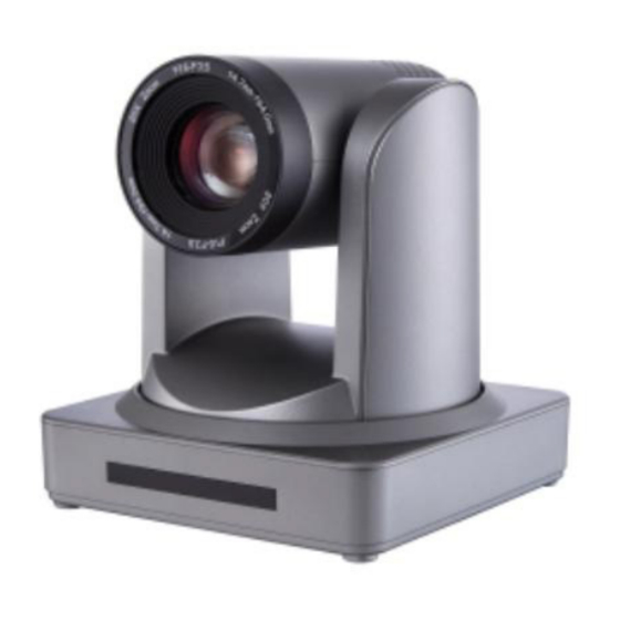
- Page 1 HD Color Video Camera HV-51 User Manual www.hameco.eu...
- Page 2 HV-51 User Manual ATTENTION Electric Safety Installation and operation must be in accordance with electrical safety standards. Transportation Avoid stress, vibration and immersion in water during transportation, storage and installation. Polarity of power supply The power supply of the product is ±12V, the max electrical current is 2A polarity of the power supply in the drawing below.
-
Page 3: Table Of Contents
HV-51 User Manual 1. Fast Installation............................5 1.1 Camera Interface Explanation....................... 5 1.2 Power-on Initial Configuration......................8 1.3 Video Output............................8 2. Product Overview............................ 11 2.1 Product Introduction..........................11 2.1.1 Product Model............................11 2.1.2 Dimension………………………………......................12 2.1.3 Accessory.............................. 12 2.2 Main Features............................ - Page 4 HV-51 User Manual 4.2.6 Network Configuration........................37 4.2.7 System Configuration.......................... 38 4.2.8 Logout..............................39 4.2.9 Wireless Network..........................40 5. Serial Communication Control....................... 40 5.1 VISCA Protocol List..........................40 5.1.1 Camera Return Command........................40 5.1.2 Camera Control Command........................41 5.1.3 Inquiry Command..........................46 5.2 Pelco-D Protocol Command List......................
-
Page 5: Fast Installation
HV-51 User Manual 1. FAST INSTALLATION 1.1 Camera Interface Explanation Figure 1.1 Interface of ST (standard) Series 1. Camera Lens 8. RS485 Input (left +,right-) 2. Camera Base 9. Audio Input Interface 3. Remote Controller Receiver Light 10. 3G-SDI interface 4. - Page 6 HV-51 User Manual Figure 1.3 Interface of U2 (USB2.0) Series 1. Camera Lens 7. RS232 Control Interface (output ) 2. Camera Base 8. USB2.0 interface 3. Remote Controller Receiver Light 9. Audio Input Interface 4. Bottom Dial Switch 10. 10/100M Network Interface 5.
- Page 7 HV-51 User Manual 1.5 HM Model(HDMI Output) 1. Camera Lens 6. RS232(IN) 2. Camera Base 7. HDMI Output 3. Remote Controller Receiver Light 8. Lan 4. Tripod Screw Hole 9.Power Supply 5. Bottom Dial Switch 1.6 U2U3 (USB2.0, USB3.0, HDMI Output) 1.
-
Page 8: Power-On Initial Configuration
HV-51 User Manual 1.2 Power on initial configuration 1) Power on: Connect DC12V power supply adapter with power supply socket. 2) Initial configuration: Power on with power indicator light on and remote control receiver light blink- ing, camera head moves from bottom left to the bottom, and then goes to the HOME position (inter- mediate position of both horizontal and vertical ),while the camera module stretches. - Page 9 HV-51 User Manual 5) USB3.0 compatible with USB2.0 output a. USB3.0 video cable connection: U3 models refer to No.7 in Figure1. 2.U2U3 models refer to No.8 in Figure1.6. b. Connect the camera and the monitor via USB3.0 video cable, open video display software, select image device, and then video output will be available.
- Page 10 HV-51 User Manual 2. Upside-down mount step www.hameco.eu...
-
Page 11: Product Overview
HV-51 User Manual 2. PRODUCT OVERVIEW 2.1.1 Product Model There are four main series according to different video formats, lens optical zooms, output interfaces and remote control modes. HV-51 IR ---IR Remote Control WR---Wireless Remote Control ST---Standard Interface (5G Wifi function optional) U2---USB2.0 Interface... -
Page 12: Accessory
HV-51 User Manual 2.1.3 Accessories Please refer to the corresponding features in this manual. Model Configur U2U3 Series ST/HD/HM Series U3 Series U2 Series ation Power adapter 1piece USB3.0 and RS232 cable 1 USB3.0 cable 1 USB2.0 cable 1... -
Page 13: Network Performance
HV-51 User Manual 7.Multiple Remote Controls: There is an IR remote and 2.4G wireless remote for options. The 2.4G wireless remote controller will not be affected by angle, distance or IR interference. Supports transpar- ent transmission functions. 8.Low-power Sleep Function: Supports low-power sleep/wake up, the consumption is lower than 500mW under sleep mode 9.Support Multiple Control Protocol: Supports VISCA, PELCO-D, PELCO-P protocols which can also be... - Page 14 HV-51 User Manual Model Camera Parameter F1.5 – F3.0 F1.6 – F3.0 F1.6 – F3.0 F1.8 – F2.4 Digital Zoom Minimum 0.5Lux (F1.8, AGC ON) Illumination 2D & 3D DNR White Balance Auto / Manual/ One Push/ 3000K/ White Balance...
-
Page 15: Interface Instruction
HV-51 User Manual PTZ Parameter Pan Rotation ±170° Tilt Rotation -30° +90° Pan Control Speed 0.1 -180°/sec Tilt Control Speed 0.1-80°/sec Preset Speed Pan 60°/sec, Tilt: 30°/sec Preset Number 255 presets (10 presets by remote controller) Other Parameter Supply Adapter... - Page 16 HV-51 User Manual 2) External interface of U3 model: Audio Input, USB 3.0 Output, LAN, DC12V Power Interface. 3) External interface of U2 model: Audio Input, USB 2.0 Output, LAN, DC12V Power Interface. www.hameco.eu...
-
Page 17: Bottom Dial Switch
HV-51 User Manual 4) External interface of HD model: Audio Input, HD Baset Output, LAN, DC12V Power Interface. 4) E5) External interface of U2U3 model: RS232 input, USB3.0, USB2.0, HDMI, LAN, DC12V power interface. 2.4.2 Bottom Dial Switch ST model , U3 model and U2 model Bottom Dial Switch diagram shown in Figure 2.6 and 2.7: ST/U2/HD model: two DIP switches are set to ON or OFF to select different modes of operation as shown in Table 2.2... -
Page 18: Rs-232 Interface
HV-51 User Manual 2.4.3 RS-232 Interface 1) ST model RS-232C interface specification as shown below Computer or keyboard and camera connection method Camera WidowsDB-91. 1.DTR 1.DCD 2.DSR 2.DSR 3.TXD 3.TXD 4.GND 4.GND 5.RXD 5.RXD 6.GND 6.GND 7.IR OUT 7.IR OUT 8.NC... - Page 19 HV-51 User Manual 3) RS232 (DB9) Port Definition Port Definition Data Carrier Detect Receive Data Transmit Data Data Terminal Ready System Ground Data Set Ready Request to Send Clear to Send Ring Indicator 4) VISCA networking as shown below:...
-
Page 20: Application Instruction
HV-51 User Manual 3. APPLICATION INSTRUCTIONS 3.1 Video Output 3.1.1 Power-On Initial Configuration Connecting the power, camera will start initial configuration the R indicator light will be flashing. When the camera returns to the HOME position (middle position for P/T),and lens finishes zooming n/out, the auto-testing is complete. -
Page 21: Remote Controller
HV-51 User Manual 3.1 Remote Control 3.2.1 Key Instructions 1. Standby Key After pressing for 3 seconds, the camera will step into standby mode. Press for 3 seconds again, the camera will self-test again and go back to HOME position. -
Page 22: Applications
HV-51 User Manual 3.2.2 Applications Finishing initialization, it can receive and execute the IR commands. Press the remote controller button, the indicator light isflashing; release the button, the indicator light stops flashing. Users can control the pan/tilt/zoom, setting and running preset positions via the IR remote controller. -
Page 23: Menu Setting
HV-51 User Manual 5) BLC Setting BLC ON / OFF: support 6) Presets Setting, Running, Clearing 1. Preset setting: to set a preset position, the users should press the “ SET PRESET ” key first and then press the number key 0-9 to set a relative preset. -
Page 24: System Setting
HV-51 User Manual 3.3.2 System Setting Move the pointer to the (Setup) in the Main Menu, click the HOME key and enter into the (System Setting) as shown below. SETUP Protocol Auto Visca Address PROTOCOL: VISCA/Pelco-P/Pelco-D/Auto Visca Address Fix... - Page 25 HV-51 User Manual 1) EXPOSURE SETTING Move the pointer to the (EXPOSURE) in the Main Menu, click the HOME and enter the (EXPOSURE SET) as follows. Mode : Auto, Manual, Shutter priority, Iris priority and Brightness priority. EXPOSURE EV : On/Off (only available in auto mode)
- Page 26 HV-51 User Manual 3) IMAGE Move the pointer to (IMAGE) in the Menu, click HOME and enter (IMAGE) as follows. IMAGE BRIGHTNESS CONTRAST SHARPNESS Brightness: 0~14 Contrast: 0~14 FLIP-H Sharpness: 0~15 Flip-H: On/Off FLIP-V Flip-V: On/Off B&W MODE COLOR B&W Mode: color, black/white...
-
Page 27: P/T/Z
HV-51 User Manual 5) NOISE REDUCTION Move the pointer to (NOISE REDUCTION) in the Menu, click HOME and enter the (NOISE REDUCTION) as follows. Move the pointer to (FOCUS) in the Menu, click HOME and enter the (FOCUS) as follows. -
Page 28: Video Format
HV-51 User Manual 3.3.5 Video Format Move the pointer to (Video Format) in the Menu, click the HOME and enter (Video Format) as follows. P/T/Z 1080P60 1080P50 1080I60 1080I50 1080P30 1080P25 Note: 720P60 720P50 1. S: 1080P60 Downward Compatibility; M: 1080P30... -
Page 29: Restore Default
HV-51 User Manual 3.3.7 Restore Default Move the pointer to (RESTORE DEFAULT) in the Main Menu, click HOME and enter the (RESTORE DEFAULT) as follows. Restore default: options: yes/no; after restoring default, the RESTORE DEFAULT video format won’t be restored. - Page 30 HV-51 User Manual Note: The IP address to be added cannot be same as that of other computers or devices. The exist- ence of this IP addressneeds to be verified before adding. Click “Start” and select “Operation” to input cmd as picture below to verify if the network segment has been successfully added.
- Page 31 HV-51 User Manual Click “OK” and open the DOS command window, input ping 192.168.5.26 and press the Enter key, it will show the message below: network segment. User can also to verify network connection using the steps above once the camera completes self-checking.
-
Page 32: Ie Log In
HV-51 User Manual 4.2 IE Log In 4.2.1 Web client 1) Web client Log In Input the IP address 192.168.5.163 of the device in the address field of browser and click Enter button to enter the Web Client logging in page as shown below. User can login as administrator and normal user. -
Page 33: Configuration
HV-51 User Manual 4.2.4 Configuration Click Configuration to enter into the device parameters setting page. These are the following options: Local configuration,audio configuration,video configuration,network configuration,PTZ configuration,internet access configuration,system configuration,for a detailed de- scription please see the following table. Menu... -
Page 34: Video Configuration
HV-51 User Manual 4.2.5 Video configuration 1) Video encoding Code stream:Stream: Different video output mode setting, uses different streams. (Main stream,secondary stream) Compression Format: Set the video compression format,save and reboot to take it effect (primary / secondary stream default:H.264,H.265 optional) - Page 35 HV-51 User Manual 3) Video Parameters a,Focus: Focus mode,focus range,focus sensitivity can be set. Focus Mode: set the focus mode (the default auto,manual optional) Focus range: set the focus range (the default middle,the upper and lower optional) Focus Sensitivity: Set the focus sensitivity (default is low,high,medium optional) b,Exposure: Exposure mode,exposure compensation,back light compensation, anti-flicker,gain limit,wide dynamic,shutter speed,aperture value and brightness can be set.
- Page 36 HV-51 User Manual Sharpness: Set the sharpness value (default 7, 0-15 optional). Black and white mode: Set black and white mode (default color,black/white optional ). Gamma: Gamma value setting (default,0.45,0.50,0.52,0.55 optional). Flip Horizontal: Set Flip Horizontal (default Off,On optional).
-
Page 37: Network Configuration
HV-51 User Manual 4.2.6 Network configuration 1) Network port Data port: set the data port,the device will restart automatically after being changed (default 3000,0-65535 optional). Web Port: Set Web port,the device will restart automatically after being changed (default is 80,0-65535 is optional). -
Page 38: System Configuration
HV-51 User Manual Equipment ownership: Users can add their own Administrative regions: Users can add their own. Alarm Zone: Users can add their own Equipment installation address: Users can add their own Local SIP Port: 5060 Range 0-65535 GB28181 Server Address: IP address of the computer... -
Page 39: Logout
HV-51 User Manual Note: Please note the case-sensitivity of the user name and password. If logging in with a common user name and password ,one does not have configuration privileges and- can only operate preview,playback,and log off. 4) Version upgrade MCU version V2.0.0.16 2015-12-18... -
Page 40: Wireless Network
HV-51 User Manual Password: password can be set,password can be changed if only checked encryption. Click on the “Save” button to display “Parameter saved successfully” message,set to take effect Note: SSID and password should be filled in correctly, otherwise, if restarted after only if encryption is checked off, the wireless WiFi connection will not be successful. -
Page 41: Camera Control Command
HV-51 User Manual 5.1.2 Camera control command Command Function Command packet Note AddressSet Broadcast 88 30 0p FF p: Address setting IF_Clear Broadcast 88 01 00 01 FF I/F Clear CommandCancel 8x 21 FF 8x 01 04 00 02 FF... - Page 42 HV-51 User Manual Command Function Command packet Note 4500k 8x 01 04 35 08 FF 5500k 8x 01 04 35 09 FF CAM_WB 6000k 8x 01 04 35 0A FF 7000k 8x 01 04 35 0B FF Reset 8x 01 04 03 00 FF...
- Page 43 HV-51 User Manual Command Function Command packet Note 8x 01 04 0E 02 FF Exposure Compensation Amount Setting CAM_ExpComp Down 8x 01 04 0E 03 FF Direct 8x 01 04 4E 00 00 0p 0q FF pq: ExpComp Position...
- Page 44 HV-51 User Manual Command Function Command packet Note 8x 01 04 0E 02 FF Exposure Compensation Amount Setting CAM_ExpComp Down 8x 01 04 0E 03 FF Direct 8x 01 04 4E 00 00 0p 0q FF pq: ExpComp Position...
- Page 45 HV-51 User Manual Command Function Command packet Note pqrs: Camera ID (=0000 CAM_IDWrite 8x 01 04 22 0p 0q 0r 0s FF to FFFF) 8x 01 04 06 06 02 FF SYS_Menu Turn off the menu screen 8x 01 04 06 06 03 FF...
-
Page 46: Inquiry Command
HV-51 User Manual Command Function Command packet Note Home 8x 01 06 04 FF VV: Pan speed 0x01 (low speed) to 0x18 (high speed) WW: Tilt speed 0x01 (low Pan_tiltDrive speed) to 0x14 (high Reset 8x 01 06 05 FF... - Page 47 HV-51 User Manual Command Function Command packet Note CAM_WBModeInq y0 50 0B FF 7000K CAM_RGainInq 8x 09 04 43 FF y0 50 00 00 0p 0q FF pq: R Gain CAM_BGainInq 8x 09 04 44 FF y0 50 00 00 0p 0q FF...
- Page 48 HV-51 User Manual Command Function Command packet Note y0 50 02 FF CAM_LR_Rever- 8x 09 04 61 FF seInq y0 50 03 FF y0 50 02 FF CAM_PictureFlipInq 8x 09 04 66 FF y0 50 03 FF CAM_ColorSatura- p: Color Gain setting 0h...
-
Page 49: Pelco-D Protocol Command List
HV-51 User Manual Command Function Command packet Note P: 0~E Video format 0:1080P60 8:720P30 1:1080P50 9:720P25 2:1080i60 A 1080P59.94 3:1080i50 B 1080i59.94 VideoSystemInq 8x 09 06 23 FF y0 50 0p FF 4:720P60 C 720P59.94 5:720P50 D 1080P29.97 6:1080P30 720P29.97... -
Page 50: Pelco-P Protocol Command List
HV-51 User Manual Function Byte1 Byte2 Byte3 Byte4 Byte5 Byte6 Byte7 Call Preset 0X07 0x00 Preset ID Query Pan Position 0x51 0x00 0x00 Query Pan Position Value High Value Low 0x59 Response Byte Byte Query Tilt Position 0xFF Address... -
Page 51: Camera Maintenance And Troubleshooting
HV-51 User Manual Function Byte1 Byte2 Byte3 Byte4 Byte5 Byte6 Byte7 Byte8 Query Tilt 0x53 0x00 0x00 Position Query Tilt Value High Value Low Position 0x5B Byte Byte Response 0xA0 Adress 0x00 0xAF Query Zoom 0x55 0x00 0x00 Position... - Page 52 HV-51 User Manual 5) Serial port does not work a, Check whether the camera serial device protocol, baud rate, and address is consistent. b, Check whether the control cable is connected properly c, Check whether the camera working mode is the normal operating mode (see Table 2.2 and Table 2.3) 6) Cannot log in to web pages a, Check whether the camera is showing normally.
-
Page 53: Product Disposal
HV-51 User Manual PRODUCT DISPOSAL Safety For your own safety, this product should only be used with CE and RoHS approved equipment. Using this product with non-approved equipment would void the warranty. Disposal of your product Municipal waste stream. Old appliances must be collected separately in order to optimise the recovery and recycling of the materials to reduce the impact on human health and the environment.
Need help?
Do you have a question about the HV-51 and is the answer not in the manual?
Questions and answers