Table of Contents
Advertisement
Quick Links
Advertisement
Table of Contents

Related Manuals for Alpinion Medical Systems X-CUBE 70


Summary of Contents for Alpinion Medical Systems X-CUBE 70
- Page 1 X-CUBE 70 DIAGNOSTIC ULTRASOUND SYSTEM Quick Guide Rev. 0 (ENG) D/N: 70003656...
- Page 2 This document and the information contained in it is proprietary and confidential information of ALPINION MEDICAL SYSTEMS (hereinafter called Alpinion) and may not be reproduced, copied in whole or in part, adapted, modified, disclosed to others, or disseminated without the prior written consent of Alpinion.
- Page 3 Original Documentation Original Documentation The original document was written in English and published in PDF File. The English version of the user documentation is intended for the countries of the European Union, North or South America, Asia as well as other worldwide countries where the products are sales and used.
- Page 4 • This product is intended for ultrasound diagnosis and cannot be used in your PC environment. We are not responsible for any problems that occur in such situations. X-CUBE 70 Quick Guide...
- Page 5 Regulatory Requirements Classifications • Type of protection against electrical shock: Class I • Degree of protection against electrical shock (Patient connection): Type BF equipment • Degree of protection against harmful ingress of water: Ordinary equipment and all of applied parts (IPX7, IPX8) except ECG meet ingress protection level according to IEC 60529. •...
- Page 6 • EN 61000-4-8:2010 (IEC 61000-4-8:2009) • EN 62304:2006+A1:2015 (IEC 62304:2006/AMD1:2015) • EN 62366-1:2015 (IEC 62366-1:2015) • MEDDEV 2.12/2 Rev.2 • MEDDEV 2.7.1 Rev.4 • NEMA UD2:2004 (R2009) • Medical Devices Regulations (SOR/98-282) • 의료기기법, 의료기기법 시행령, 의료기기법 시행규칙 X-CUBE 70 Quick Guide...
- Page 7 ALPINION USA (Kevin Chun) 21222 30th Dr SE Ste C-122 Bothell, WA 98021, United States +1 425 949 1059 Asia countries ALPINION MEDICAL SYSTEMS Co., Ltd. ALPINION MEDICAL SYSTEMS Co., Ltd. 5FL, I Dong, 77, Heungan-daero 81beon-gil, Dongan-gu, Anyang-si, Gyeonggi-do, Republic of Korea...
- Page 8 Dongan-gu, Anyang-si, Gyeonggi-do, Republic of Korea Telephone: +82 2 3282 0903 Fax: +82 2 851 5593 www.alpinion.com Copyright © ALPINION MEDICAL SYSTEMS Co., LTD, All rights reserved. This product complies with regulatory requirements of the following European Directive 93/42/EEC concerning medical devices.
- Page 9 Revision History Revision History The revision history of this manual is as follows. Date (YYYY/MM/DD) Description Rev. 0 2021/04/26 Initial Release Please verify that you are using the latest revision of this document. If you need to know the latest revision, contact your local agent or local Alpinion sales representative.
-
Page 11: Table Of Contents
Table of Contents 1. Getting Started ...................1-1 Introduction ......................1-2 Documentation ........................1-2 System Feature ........................1-2 Console Overview ....................1-5 System_Front View ......................1-5 System_Rear View ........................ 1-6 System_Side View ......................... 1-7 Monitor and Touch Screen ....................1-8 Control Panel ........................1-10 QWERTY Keyboard ...................... - Page 12 Starting a New Exam on an Existing Patient .................2-5 Retrieving Patient Information via Worklist ................2-5 Ending an Exam ........................2-6 Optimizing the Image .....................2-7 2D Mode Controls......................... 2-7 M Mode Controls ........................ 2-15 CF Mode Controls ....................... 2-17 PD Mode Controls ......................2-20 PWD Mode Controls ......................
- Page 13 Equipment and Personnel Safety ................4-3 Equipment and Personnel Safety ..................4-3 Caution for Moving the System ....................4-5 Caution for Using Monitor ....................4-5 Caution for Using Control Panel ...................4-5 Patient Safety ......................4-6 Patient Identification ......................4-6 Patient Data .......................... 4-6 Diagnostic Information ......................4-6 Mechanical Hazards ......................
-
Page 15: Getting Started
Getting Started This chapter introduces the followings: Introduction ........................1-2 Console Overview ......................1-5 System Start-Up ......................1-18 Transducer ........................1-19 System Preset ......................1-21 Configuring Connectivity .................... 1-24... -
Page 16: Introduction
Introduction Documentation The X-CUBE 70 Quick Guide (TRANgLATED) provides basic information needed by the user to operate the system safely. For more information, see the X-CUBE 70 User Manual. System Feature Table 1-1 System feature • Height: 1440/1605 mm • Width: 580 mm Physical Dimensions •... - Page 17 • Xpeed™ • Full SRI™ • gpatial Compounding Image (gCI) • Panoramic • Live HQ™ • Needle Vision™ Plus • Contrast Enhanced Ultrasound (CEUS) • ECG Image Processing Technology • Elastography • X Point Shear Wave • X MicroView • Filter Method Tissue Harmonic Image (FTHI) •...
- Page 18 • Distance • Ellipse • Trace • Spline • Velocity • Time • Slope Available Measurements • Acceleration • Auto Calculation • gemi-Auto Calculation • Auto IMT • Auto NT • Auto EF • X Auto Biometry • Verification • DICOM gtorage •...
-
Page 19: Console Overview
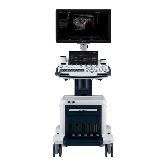
Console Overview System_Front View There are the main components of your system: Figure 1-1 X-CUBE 70 System (Front view) Component Component Monitor Control panel swivel button LED lamp Transducer cable holder Touch screen Control panel up/down button Gel warmer Speaker... -
Page 20: System_Rear View
System_Rear View Figure 1-2 X-CUBE 70 System (Rear view) Component Component Transducer holder I/O panel Endocavity transducer holder gystem On/Off switch AC outlet AC inlet NOTE When connecting an external monitor to your system, use the monitor with 1366 x 768 or higher resolution. -
Page 21: System_Side View
System_Side View Figure 1-3 X-CUBE 70 System (Side view) Component Component Monitor arm gide tray (Option) Rear handle Body base Speakers Caster lock Body cover Caster Console Overview... -
Page 22: Monitor And Touch Screen
Monitor and Touch Screen Figure 1-4 Monitor buttons Component Component LED lamp button Down ( ) button Up ( ) button Touch screen Brightness buttons Mode/gelect ( ) button CAUTION The LED lamp may overheat. Be careful not to directly touch it to avoid injury. Getng gtarted... - Page 23 Adjusting the monitor's contrast and brightness To adjust the brightness of the monitor, Press the Mode/Select ( ) button on the monitor once. To increase the brightness, press the Up ( ) button. Press the Down ( ) button to decrease the brightness.
-
Page 24: Control Panel
Control Panel The control panel can be used for controlling the system. Figure 1-5 Control panel layout Power on/off key TGC slides USB port QWERTY keyboard goft keys Trackball 1-10 Getng gtarted... - Page 25 Table 1-2 Key description Control Control Name Description SLEEP Activate gleep mode. Access user-defined functions. User-Defined The function for each key can be assigned in Utility > Setup Keys (U1–U6) > SystemPreset > User Setting > User Defined Key. Activate M mode. Activate PW mode.
- Page 26 Control Control Name Description Set or Cursor function may be assigned to these keys. The function for each key can be assigned in Utility > Setup > SystemPreset > System > Control Panel > Key > Set the Set/Cur Cursor and Set Keys. •...
-
Page 27: Qwerty Keyboard
QWERTY Keyboard The QWERTY keyboard is available which you can enter text or perform special functions. Figure 1-5 QWERTY keyboard Using the special keys Table 1-3 Special key description Control Control Name Description Quick ID Access the Quick ID screen. Patient Browser Access the E-View screen. - Page 28 Control Control Name Description Help Access the electronic manual. Biopsy ghow the biopsy guideline. Speaker Volume Turn up/down the speaker volume. Reverse Flip the image 180 degrees left/right. Clear All Clear your input or cancel your selection. Hide Hide the current menu screen. Activate Xpeed to automatically optimize image Xpeed parameters on the live screen.
-
Page 29: Touch Screen
Touch Screen Your ultrasound system has the touch screen that enables you to easily access menus or adjust options on the current monitor display. With the touch screen, you can also enter text instead of using the QEWRTY keyboard. gimply touch the menu or option you want. Figure 1-6 Touch screen Table 1-4 Touch screen description Control... - Page 30 Control Description Display the labels for the current functions of the soft keys. gome modes and applications have two rows of labels, while some have no soft keys. Soft Key Labels You can select the functions assigned to the soft keys by touching the labels or by pressing or rotating the knob below the label.
-
Page 31: Image Display
Image Display The image display consists of an ultrasound image, application information, patient information, and indicators. Figure 1-7 Image display Hospital logo & name Image area Current date & time Image parameter Patient ID, Patient name Clipboard indicator Operator ID, Transducer name Image clipboard Mechanical index, Thermal index gtatus bar: gymbol lock, Caps lock,... -
Page 32: System Start-Up
System Start-Up Power On Make sure that the power cord is plugged into the power outlet. CAUTION Make sure that the system power is supplied from a separate and properly rated power outlet. Push the System On/Off switch to turn on the system power on the bottom rear of the system. -
Page 33: Transducer
Transducer Connecting the Transducer You can connect the transducer to the transducer port when the system is powered off or on. Make sure that you press the [Freeze] key on the control panel before connecting the transducer. CAUTION Do not touch the patient when connecting or disconnecting a transducer. Check if you press the [Freeze] key on the control panel. -
Page 34: Activating The Transducer
Activating the Transducer Use the following procedure to activate the transducer and application. Touch Transducer on the touch screen. The dialog box for transducer and application selection appears. gelect the desired transducer, application and preset on the touch screen. NOTE Default transducer for the selected preset or default preset for the selected transducer is selected automatically. -
Page 35: System Preset
System Preset In each preset menu, you can configure different default setngs for its submenus. System Preset Display Figure 1-8 System preset display System presets Exit Preset menus gave & Exit System Preset 1-21... -
Page 36: System Preset Menus
System Preset Menus To access preset menus, select the desired menu on the touch screen. Figure 1-9 System preset touch screen Preset menu Description Customize the system configurations such as general setngs, control System panel, peripheral, patient info, and monitor calibration. Annotation Customize the comment and body pattern setngs. -
Page 37: General Workflow
General Workflow To change system parameters, Touch Utility on the touch screen. Touch Setup on the touch screen. Touch the SystemPreset tab on the touch screen. The System Preset screen appears. Select the appropriate preset you want to specify. Select the preset menu on the touch screen. Change values for the parameters you want to change. -
Page 38: Configuring Connectivity
Configuring Connectivity You use Connectivity preset to configure the network connection and DICOM protocols. DICOM is an abbreviation of Digital Imaging and Communications in Medicine. This is a standard protocol for handling, storing, printing, and transmitng information in medical imaging. Using the DICOM option, you can send or print images after connecting the system and PACS. - Page 39 Network The Network menu allows you to set up Internet protocol. You need a separate IP address for your system. NOTE To set up Internet Protocol, contact your hospital’s network administrator. Local Area ❚ gpecify the following IP address setngs: •...
- Page 40 Network Storage The Network Storage menu allows you to customize options for sending backup data to ghared directory. You can add and edit a network storage device. To enter the Network Storage menu, – Go to General menu and click Network Storage on the bottom right of the display. To add a network storage device, Click New.
- Page 41 CubeNote The CubeNote menu allows you to set up the network options for accessing to the CubeNote Control Server. You can add and edit a CubeNote Control server device. To enter the CubeNote menu, – Go to General menu and click CubeNote on the bottom right of the display. To add a Control gerver device, Enter a hospital code in the Hospital Code field.
- Page 42 Common DICOM service parameters There are certain parameters that may need to be set up for each DICOM service. The parameters are described on the following DICOM services. NOTE • DICOM is an optional service. To use this service, you need DICOM installation. •...
- Page 43 Verify ❚ gelect a destination. Click Verify to start verification. When the verification is completed, the one of the following icons is shown. Icon Description Successfully connected Failed in connection In progress View ❚ View allows you to view the connectivity architecture of your system such as configured DICOM service and network structured tree.
- Page 44 Properties ❚ • Enable Structure Report: get to send a report with images. • Enable Raw data of Compact 3D/4D (Image Arena™): get to send a 3D/4D image with raw data for Image Arena™. • Enable Multiframe: get to save multi-frame Cine images in the DICOM gtorage. •...
- Page 45 Search Criteria ❚ • DICOM Tag: gelect information type that you want to define for search parameters such as Modality and Referring Physician’s name. • Value: Enter the value of the selected tag item. • Add to list: Add tag and value to the list of search criteria. •...
-
Page 47: Performing An Exam
Performing an Exam This chapter introduces the followings: Beginning an Exam ....................... 2-2 Optimizing the Image ....................2-7 Managing Image and Patient Data ................2-31 Measurement and Report ..................2-36... -
Page 48: Beginning An Exam
Beginning an Exam Patient Screen The following components are shown on the screen: Figure 2-1 Patient screen Assistant Exam information Function selection Patient list/Study list Patient information Save & Exit, Exit Application selection Performing an Exam... -
Page 49: Starting A New Patient
Starting a New Patient Touch Patient on the touch screen. The Patient screen appears. The cursor positions on the Patient ID field. Enter the patient information using the alphanumeric keyboard. NOTE To automatically generate a patient ID with current date and time, –... -
Page 50: Quick Id
Quick ID Press the [Quick ID] key on the QWERTY keyboard. Or select Quick Register on the touch screen. The Quick ID screen appears. Enter Patient ID, Name, Birth Date, and Sex. Only OB application shows the LMP and EDD fields. -
Page 51: Starting A New Exam On An Existing Patient
Starting a New Exam on an Existing Patient NOTE When you register a patient, the study list appears on the display. If the patient is not registered, the patient list appears instead. Touch Patient on the touch screen. The Patient screen appears. Select a search criteria (Patient ID, Patient Name, Birth Date, Sex, Exam Date, and Locked) from the Search drop-down list and enter a search keyword. -
Page 52: Ending An Exam
Ending an Exam When you end an examination, all images of the current study are saved in the local hard disk. – Touch End Exam on the touch screen to save the current study. – You can also end a study by selecting New Patient on the Patient screen. NOTE You can return to the Patient screen after ending the current study. -
Page 53: Optimizing The Image
Optimizing the Image 2D Mode Controls Gain Gain allows you to Increase or decrease in the amount of echo information displayed in an image. It may have the effect of brightening or darkening the image if sufficient echo information is generated. To increase or decrease overall gain, rotate the [2D] key on the control panel. - Page 54 Focus Convex array, linear array, and phased array transducers support multiple transmit focus zones, which you can select in 2D-mode images. Focal zone markers display on the left side of the image screen. Focus Num ❚ To increase or decrease the number of focal zones, press the [Focus] key on the control panel and then rotate the key clockwise or counter-clockwise.
- Page 55 Angle Steer In 2D mode, you can tilt an image left or right by using a linear transducer. To adjust the angle steer, rotate the [Angle] key clockwise or counter- clockwise on the control panel. The each level of the angle increment/decrement is 5 degrees. Harmonic Tissue Harmonic Imaging (THI) is a system feature that can enhance the contrast resolution with fine tissue differentiation, benefiting patients with poor images.
- Page 56 EX-FOV On endocavity transducers, EX-FOV provides wide angle field of view. To activate or deactivate EX-FOV, select the EX-FOV icon ( ) on the touch screen. Virtual Convex On linear transducers, virtual convex provides a larger field of view in the far field. To activate or deactivate the virtual convex, select Virtual on the touch screen.
- Page 57 Strain Elastography (Option) Strain Elastography is a non-invasive method used to help detect or classify tumors. It shows the spatial distribution of tissue elasticity properties in a region of interest by estimating the strain before and after tissue distortion caused by external or internal forces. For more information, please refer to "Strain Elastography"...
- Page 58 Needle Vision™ Plus (Option) Needle Vision™ Plus is a needle enhancement feature that can enhance viewing of the needle to assist you in guiding the needle to the target anatomy. For more information, please refer to "Needle Vision™ Plus" in User Manual. To perform Needle Vision™...
- Page 59 Full SRI™ Full SRI™ is a more powerful SRI feature that allows you to adjust the SRI level according to your image condition or imaging mode. The full SRI feature is available in 2D, 3D, and 4D modes. To adjust the full SRI, select < or > of FullSRI on the touch screen. Spatial Compound Spatial compound allows you to combine different steering frames to form a single frame at real-time frame rates.
- Page 60 Colorize Colorize is the colorization of a conventional 2D mode image or Doppler Spectrum to enhance the user's ability to discern 2D mode, M mode, and Doppler mode intensity valuations. Colorize is NOT a Doppler mode. To adjust the colorize, rotate the Colorize soft key clockwise or counter-clockwise.
-
Page 61: M Mode Controls
M Mode Controls Cine In M mode, image trace information can be recalled. When freezing an image, a certain time frame (M information of the last examination sequence) is stored in the loop memory. The sequence can be reviewed second by second. Full Timeline Full timeline expands the display to full timeline display. - Page 62 M mode zoom When the system is in M mode, you can magnify a portion of the reference image using M mode zoom function. To adjust the M mode zoom, In M mode or 2D mode with the M-line displayed, press the [Zoom] key on the control panel to activate Write zoom.
-
Page 63: Cf Mode Controls
CF Mode Controls Positioning, sizing, and steering the ROI When you press the [CF] key in 2D mode, the color window or ROI appears on the image. The initial location and the shape of the window depend on the active transducer and default imaging depth. - Page 64 Adaptive Blend Adaptive Blend superimposes a translucent color image over a 2D image in the color image area. You can adjust the transparency of the color image easily to demonstrate the tissues behind the color. To activate or deactivate this function, select Adaptive Blend on the touch screen.
- Page 65 Ensemble Ensemble allows you to select the density of the scan line. With increasing the number of ensemble, the frame rate decreases. To adjust the ensemble, rotate the Ensemble soft key clockwise or counter-clockwise. Wall Filter Wall filter filters out clutter signals caused from vessel movement. To raise or lower the wall filter, rotate the WF soft key clockwise or counter-clockwise.
-
Page 66: Pd Mode Controls
PD Mode Controls Micro Vascular Imaging (Option) MVI aims to visualize low velocity and small diameter blood vessel. To activate or deactivate MVI mode, select X+ MicroView on the touch screen. Directional power Doppler Imaging (DPDI) DPDI (Directional power Doppler Imaging) function shows information on the intensity and direction of blood flow. - Page 67 Flow State Flow State adjusts the PRF of the color image. To adjust this function, select < or > of Flow State on the touch screen. Angle Steer In Power Doppler mode, you can tilt an image left or right by using a linear transducer. To adjust the angle steer, select <...
-
Page 68: Pwd Mode Controls
PWD Mode Controls PW Doppler angle Angle between the direction of reflector motion and the direction of propagation of the ultrasound beam. PW Doppler effect Phenomenon whereby there is a change in the perceived frequency of a sound source relative to the transmitted frequency when there is a relative motion between a sound source and the listener. - Page 69 Doppler sample volume length Size the sample volume gate. To increase or decrease the gate size, select < or > of SV on the touch screen. You can adjust the sample volume gate length whenever the sample volume gate appears on the display. AutoCalc Activate the calculation automatically when the system is in a state of freeze or live.
- Page 70 Sensitivity Sensitivity is used to adjust the trace to follow the waveform for signal strength. To adjust the sensitivity, select < or > of Sensitivity on the touch screen. Sound CAUTION Doppler audio sounds may change abruptly. Adjust the volume of sound in smaller increments to avoid startling the patient.
-
Page 71: Cwd Mode Controls
CWD Mode Controls Update (D pause) In simultaneous mode of 2D and Doppler modes, you can pause a Doppler image and move the image to the 2D live screen by adjusting the Doppler gate. To activate the update, press the [Uptate] key on the control panel. -
Page 72: 3D And 4D Modes Operation Controls
3D and 4D Modes Operation Controls Description In 3D/4D setup mode, press to obtain a 3D or 4D image. Freeze In 3D mode, press to switch to 3D/4D setup mode. In 4D mode, press to switch to 3D mode. Press again to return to 4D mode. In 3D or 4D mode, rotate the X axis;... - Page 73 Performing 3D image scanning In 3D mode, you can acquire 3D images through an acquisition interface. Obtain a 2D image and optimize the image for the best quality. On the control panel, press the [3D/4D] key. Touch the 3D tab on the touch screen. The yellow-colored ROI and soft menus for 3D mode appear.
-
Page 74: Other Controls
Other Controls Zooming an image You can magnify a region of interest (ROI) in a live image or in Cine mode. The zoom option magnifies the ROI on the display. There are two zoom functions that you can use: Read zoom and Write zoom –... - Page 75 Annotating an image Press the [Text] key on the control panel to activate Annotation mode. To configure the default position of the comment cursor, use [Trackball] to place the comment cursor to the desired location of the image screen and select Set Home on the touch screen.
- Page 76 Body Pattern To insert a body pattern, To activate Body Pattern, press the [Body Pattern] key on the control panel. A list of body patterns appears on the touch screen. A default body pattern is displayed automatically when Body Pattern is activated. NOTE The body pattern list can be configured in Utility >...
-
Page 77: Managing Image And Patient Data
Managing Image and Patient Data Clipboard Capturing onto the clipboard Press the [P1] key to capture images onto the clipboard. You can see thumbnail images on the clipboard. NOTE The print key is programmable. You can assign the P1, P2, P3 and P4 key functions in Utility > Setup >... -
Page 78: E-View
E-View The system provides the E-View feature that allows fast and easy image management. The E-View feature allows you to view the whole patient from local database or removable media, export/import, save as with PC friendly format and send DICOM images to remote server over the network. - Page 79 Patient Browser/Send To CD/DVD, USB/USB HDD, Network ❚ Select Local HDD from the Source drop-down list. Select the patient(s) from the patient list. Insert your removable media to the media tray properly. Select Send To on the touch screen, or select Send To on the function selection. The dialog box appears.
- Page 80 PACS ❚ PACS allows you to transfer patient(s) data to the DICOM device such as DICOM storage or DICOM Print. To send from the local HDD to a DICOM device, Select Local HDD from the Source drop-down list. Select the patient(s) from the patient list. Select Send To on the touch screen, or select Send To on the function selection.
- Page 81 Reviewing an image Select an image and select Review on the touch screen. The image is shown on the scan screen. Ending a study To end a study immediately, – Touch End Exam on the touch screen. Managing Image and Patient Data 2-35...
-
Page 82: Measurement And Report
Measurement and Report Basic Measurement Operations To begin the measurement, On the control panel, press the [Caliper] key. Use [Trackball] to move the point. Press the [Set] key to fix the point. To modify a measurement, Click the result value you want to change from the Result window. The caliper is activated. -
Page 83: Basic Measurements
Basic Measurements The basic measurements are available in the following imaging modes: • 2D mode • M mode • Doppler mode 2D mode measurements Distance ❚ 1 Distance Select Distance on the touch screen. The start point appears. Use [Trackball] to move the marker to the start point. Press the [Set] key to fix the point. - Page 84 Circumference and Area ❚ Ellipse Select Ellipse on the touch screen. The start point appears. Use [Trackball] to move the marker to the start point, and press the [Set] key. The first point is fixed, and the second point appears. Use [Trackball] to move the marker to the second point, and press the [Set] key.
- Page 85 Angle ❚ Angle 3 Points Select Angle on the touch screen. The start point appears. Use [Trackball] to move the marker to the start point, and press the [Set] key. The first point is fixed, and the second point appears. Use [Trackball] to move the marker to the second point.
- Page 86 %Stenosis ❚ Two diameters percent stenosis calculation Select %Stenosis on the touch screen. The start point appears. Measure the larger diameter (D1) of the stenosis using [Trackball], and press the [Set] key. Measure the smaller diameter (D2) of the stenosis using [Trackball], and press the [Set] key.
- Page 87 Volume ❚ 3 Distance volume Select Volume on the touch screen. The start point appears. Use [Trackball] to move the marker to the start point, and press the [Set] key. The first point is fixed, and the second point appears. Use [Trackball] to move the marker to the second point, and press the [Set] key again.
- Page 88 Disk Volume ❚ Trace Select DiskVolume on the touch screen. The start point appears. Use [Trackball] to move the marker to the start point, and press the [Set] key. The first point is fixed, and the second point appears. Use [Trackball] to create a trace of the structure with the second point. Press the [Set] key to complete the trace.
- Page 89 A/B Ratio ❚ Two diameters ratio Select A/B Ratio on the touch screen. The start point appears. Measure the first diameter (D1) of the ratio using [Trackball], and press the [Set] key. Measure the second diameter (D2) of the ratio using [Trackball], and press the [Set] key.
- Page 90 Elasto Size Compare ❚ NOTE Elasto Size Compare is only available to use on freezing in Elastography mode. Select Elasto on the touch screen to enter Elastography mode. Live Dual mode is displayed. Perform the scan. Proper manual compression/decompression is displayed by the colored strain map.
- Page 91 Elasto Strain Ratio ❚ NOTE Elasto Strain Ratio is only available to use on freezing in Elastography mode. Select Elasto on the touch screen to enter Elastography mode. Live Dual mode is displayed. Perform the scan. Proper manual compression/decompression is displayed by the colored strain map.
- Page 92 M mode measurements Distance ❚ 1 Distance Select Distance on the touch screen. The vertical line and the horizontal line are perpendicular to each other. Use [Trackball] to move to the point of intersection, and press the [Set] key. The start point is fixed, and the end point appears. Use [Trackball] to move the point, and press the [Set] key again.
- Page 93 Slope ❚ Select Slope on the touch screen. The vertical line and the horizontal line are perpendicular to each other. Use [Trackball] to move to the point of intersection, and press the [Set] key. The start point is fixed, and the end point appears. Use [Trackball] to move the point, and press the [Set] key again.
- Page 94 A/B Ratio ❚ Distance ratio Select A/B Ratio and then select Distance on the touch screen. The start point appears. The vertical line and the horizontal line are perpendicular to each other. Measure the first vertical diameter (D1) of the ratio using [Trackball], and press the [Set] key.
- Page 95 D mode measurements Velocity ❚ Select Velocity on the touch screen. The vertical line and the horizontal line are perpendicular to each other. Use [Trackball] to move to the point of intersection, and press the [Set] key. The measured value is fixed. The velocity (Vel) and pressure gradient (PG) are shown on the Result window.
- Page 96 Resistivity Index (RI) ❚ Select RI on the touch screen. The vertical line and the horizontal line are perpendicular to each other. Use [Trackball] to move to the point of intersection, and press the [Set] key. The start point is fixed, and the end point appears. Use [Trackball] to move the point and press the [Set] key again.
- Page 97 A/B Ratio ❚ Velocity ratio Select A/B Ratio on the touch screen. And select A/B Ratio and then select Velocity on the touch screen. The vertical line and the horizontal line are perpendicular to each other. Measure the first point (V1) of the ratio using [Trackball], and press the [Set] key. Measure the second point (V2) of the ratio using [Trackball], and press the [Set] key.
- Page 98 Heart Rate (HR) ❚ Select HR on the touch screen. The vertical line and the horizontal line are perpendicular to each other. Use [Trackball] to move to the point of intersection, and press the [Set] key. The start point is fixed, and the end point appears. Use [Trackball] to move the point, and press the [Set] key again.
-
Page 99: Viewing And Editing A Worksheet
Semi Auto Trace ❚ In PW mode, select the desired measurement item and then select Semi Auto Trace on the touch screen. The start point appears. Use [Trackball] to move the marker to the start point of the waveform and press the [Set] key. - Page 100 If a worksheet has more data on a second page, to view the next page, – Rotate the Select Page soft key. To exit the worksheet page and return to the scan mode, do one of the following: – Press the Exit key on user-defined key. –...
- Page 101 To select a method, Use [Trackball] to move the cursor over the value in the Method column and press the [Set] key. Select a method from the drop-down list. • Last: Last measurement that was taken • Aver: Average of the measurements taken •...
- Page 102 Printing a report To print a report via a standard printer, – Select Print on the touch screen. To capture the report screen, – Press the [P1], [P2], [P3] or [P4] key on the control panel. NOTE • A default standard printer can be configured in Utility > Setup > SystemPreset > System > Peripheral >...
-
Page 103: After The Exam Is Over
After the Exam is Over This chapter introduces the followings: Data Backup........................3-2 System Care and Maintenance ..................3-4 Transducer Care and Maintenance ................3-6... -
Page 104: Data Backup
Data Backup Youraxyrloitruiteritttingiroerpxtitn r nfoeaxtionrfiltiriuctrxirpxtitn ’irbxi cr nfoeaxtionrxndr icxnntdr axgtirbtcxuitrofrptyi cxlritockir or ttrpeoduc roer n tenxlrteeoei.rTttetfoet,ryour itouldrbxckrupruiteritttingirxndrpxtitn r nfoeaxtionrdx xronrxretgulxerbxi i. Backup/Restore The Backup/Restorerpetit rxllowiryour orbxckuprxndreti oetrpxtitn rdx x,riyi tarxndruite- dtfintdrconfiguextioni.rYourcxnritltc rxri oexgtratd xr(CD,rDVD,rUSBrflxitrde Ot,rUSBrtxedr d ik,rxndrnt woekri oexgt)r orptefoear ttrbxckup.r NOTE TorixOtr axgtirpteaxntn ly,rxOo drui ngr ttrlocxlrtxedrd ik.rRtgulxelyrbxckrupr ttr axgtr xect Otr orxri oexgtratd x. - Page 105 Toreti oetr ttruiterpetit rdx x, NOTE Mxktriuetr tx r ttriofwxetrOtei onrofr ttrdx xr ir ttrixatrxir ttriyi ta’iriofwxetrOtei on.r IfrN T,ryouraxyrno rptefoear ttreti oextion. Inite rxratd xronryoueriyi ta. Stltc r ttruiterpetit (i)ryourwxn r oreti oet. Ifryoueratd xr irUSBrflxitrde Ot,ritltc r ttruiterpetit (i)ryourwxn r oreti oetrfeoar ttr bxckuprl i .
-
Page 106: System Care And Maintenance
System Care and Maintenance I r ir ttretiponi b l yrofr ttruiter orOte fyr tx r ttrul exioundriyi tar irixftrfoerd xgnoiticr optextionronrxrdx lyrbxi i.r xctrdxy,rpe oer orui ngr ttriyi ta,rptefoeartxctrofr ttri tpir nr ttr daily checklist. CAUTION • Tttriyi tardotirno rcon x nrxnyroptex oeriteO ctxbltr n tenxlrcoapontn i.r niuetr tx r unauthorized personnel do not tamper with the unit. -
Page 107: Monthly Maintenance
Monthly Maintenance WARNING Wttnr ttrL Drlxaprnttdir orbtretplxctd,rcon xc r ttrALPINI NriteO ctretpetitn xtiOt. CAUTION TorxOo drtltc e cxlritockrtxzxed,rdorno retaoOtrpxntliroercoOteirfeoar ttrconiolt.rTt ir iteO ctraui rbtrptefoeatdrbyrquxl fitdriteO ctrpteionntl.rFx luetr ordoriorcouldrcxuitrxr serious injury. NOTE Torax n x nr ttrixft yrxndrfunctionxl yrofr ttrul exioundriyi ta,rax n tnxnctraui rbtr ptefoeatdrtOteyr12raon ti.r ltc e cxlrixft yr ti iraui rxliorbtrptefoeatdrx retgulxer n teOxlirxiriptc fitdrbyrlocxlrixft yretgulxtioni.rRtfter or ttriteO ctraxnuxlrfoer ttrtltc e cxlr leakage test. -
Page 108: Transducer Care And Maintenance
Transducer Care and Maintenance Cleaning and Disinfecting Transducers WARNING • TorxOo drtltc e cxlritockrxndrdxaxgtr or ttriyi ta,rd iconntc r ttr exniducterbtfoetr cltxn ngrxndrd i nftcting. • Alwxyiruitrpeo tctiOtrtytwtxerxndrgloOtirwttnrcltxn ngrxndrd i nftctingr exniductei. • Cttckr ttrtoui ng,ri ex nretl tf,rltnirxndritxlrfoerdxaxgt,rxndrcttckrfoerxnyrfunctionxlr peobltarxftercltxn ngrxndrd i nftctingr ttr exniducte. CAUTION •... - Page 109 Disinfecting the transducer WARNING • Ifrxrpet-a Etdriolutionr iruitd,rbtriuetr orobiteOtr ttriolutionrtEp extionrdx t. • Tttr yptrofrtiiiutr rw llrcon xc rdue ngruitrd c x tir ttrltOtlrofrd i nftctionretqu etdrfoer xrdtO ct.r niuetr tx r ttriolutionri etng trxndrduextionrofrcon xc rxetrxppeope x trfoer d i nftction. CAUTION •...
-
Page 110: Cable Handling
Approved List of Disinfectant, Pre-Cleaner, and Ultrasound Gel Anrxppeope x triubi xnctritouldrbtritltc tdrbxitdronr ttrl i rofrcoapxtibltrd i nftc xn i,r pet-cltxntei,rxndrgtli.rFoerfue tter nfoeaxtionrxbou rxppeoOtdrul exioundrgtl,rcltxn ng,rxndr d i nftc xn rpeoduc i,rpltxitretfter or ttretltOxn rctxp teir nr ttrUiterMxnuxl. Cable Handling Txktr ttrfollow ngrpetcxutionirw tr exniductercxblti: •... -
Page 111: Safety
Safety This chapter introduces the followings: Safety Precautions ......................4-2 Equipment and Personnel Safety ................. 4-3 Patient Safety ....................... 4-6 Anti-Virus Program ....................... 4-8 Transducer Safety ......................4-9 System Symbols and Labels ..................4-11... -
Page 112: Safety Precautions
You should make sure the safety precautions during all phases of operation, service, and repair of the X-CUBE 70 ultrasound system. If you fail to comply with these safety precautions or specific warnings in this manual, you violate safety standards in terms of design, manufacture, and intended use of this system. -
Page 113: Equipment And Personnel Safety
Equipment and Personnel Safety The concerns listed below can seriously affect the safety of equipment and personnel during a diagnostic ultrasound examination. Do not use the equipment if a safety problem is known to exist. Have the unit repaired and performance verified by qualified service engineer before returning to use. - Page 114 WARNING For patient safety, you must locate the system to easily unplug the power cord from the power outlet when a malfunction or an error occurs. WARNING Always use peripherals and accessories approved by ALPINION. You must securely connect peripherals and accessories to the system. WARNING The ultrasound diagnostic system is not intended to be used as a data storage device.
-
Page 115: Caution For Moving The System
Caution for Moving the System Be careful when moving the system. Failure to follow these precautions can result in serious injury and/or system damage. CAUTION To avoid serious injury and/or system damage when transporting from one area of use to another: •... -
Page 116: Patient Safety
Patient Safety The precautions listed can seriously affect the safety of patients undergoing diagnostic ultrasound examinations. Patient Identification When entering patient data, always ensure that the patient's name and ID number are correct. Make sure that all saved data and hard copy prints contain the patient ID correctly. Identity errors could lead to incorrect diagnosis. -
Page 117: Mechanical Hazards
CAUTION Be certain to ensure the patients' privacy data and confidentiality. Mechanical Hazards The use of damaged transducers or improper use and manipulation of the endocavity transducers may result in injury or increase the risk of infection. Inspect transducer often for sharp, pointed, or rough surface damage that could cause injury or tear protective barriers. -
Page 118: Anti-Virus Program
Finally, a few points as to why ALPINION MEDICAL SYSTEMS Co., LTD do not use the anti-virus software. Commercial anti-virus software is commonly used on general-purpose computers to detect the presence of malicious software (e.g. -
Page 119: Transducer Safety
Transducer Safety The following recommendations help to prevent preventable transducer damage and serious injuries. Handling and Care Precautions Care precautions CAUTION Failure to follow the precautions listed below can result in transducer damage and/or electric shock due to damaged electrical insulation. •... -
Page 120: Special Handling Instructions
WARNING Do not immerse the transducer into any liquid beyond the immersion level. Never immerse the transducer connector into any liquid. WARNING Do not kink, tightly coil, or apply excessive force on the transducer cable. There is a risk of electric shock due to damaged electrical insulation. -
Page 121: System Symbols And Labels
System Symbols and Labels System Symbols and Labels The following is a list of system symbols and labels for safety. They indicate that you must refer to the manual for specific information to avoid personal injury or damage to the product. Safety Symbols/ Labels Location Explanation... - Page 122 Safety Symbols/ Labels Location Explanation On the rating label for overseas: Alternating current in accordance Adjacent to the AC power and with IEC 60878-01-14 the AC power outlet Adjacent to the AC power Push-push button outlet Adjacent to the AC power Equipotentiality On the right side of the touch Universal Serial Bus...
- Page 123 Safety Symbols/ Labels Location Explanation Be very careful not to injure On the LCD caution label yourself or damage the system when rotating the monitor arm. Rear of the LCD monitor Caution label Care against pinch shall be taken. Top of the monitor arm (In accordance with IEC 60878) Rear of the system body Multi-caution label...
- Page 124 Safety Symbols/ Labels Location Explanation Bottom of the control panel System rating label for domestics On the cable port of the gel Gel warmer voltage label warmer Rear of the gel warmer Gel warmer label Name of transducer manufacturer, WEEE symbol, Transducer indicating separate collection, Certification mark...
- Page 125 5FL, I Dong, 77, Heungan-daero 81beon-gil, Dongan-gu, Anyang-si, Gyeonggi-do, Republic of Korea +82.2.3282.0903 +82.2.851.5593 www.alpinion.com Copyright © ALPINION MEDICAL SYSTEMS Co., Ltd, All rights reserved. Reproduction, adaptation, or translation without prior written permission is prohibited, except as allowed under the copyright laws.
Need help?
Do you have a question about the X-CUBE 70 and is the answer not in the manual?
Questions and answers