Download Print this page

Advertisement

Quick Links

O
O
O
S
S
S
O
S
O
S
O
S
O
S
O
S
O
S
O S
This publication supplements TO 1C-5M-2-1, dated 20 April 2017. Reference to this supplement will be made on
the title page of the basic manual by personnel responsible for maintaining the publication in current status.
O
COMMANDERS ARE RESPONSIBLE FOR BRINGING THIS SUPPLEMENT TO THE ATTENTION OF ALL AFFECTED AF PERSONNEL
S
DISTRIBUTION STATEMENT D - Distribution authorized to the Department of Defense and U.S. DoD contractors only (Administrative or
Operational Use) (10 September 2009). Other requests for this document shall be referred to AFLCMC/WLSA, 235 Byron St., Suite 19A,
O
S
Robins AFB, GA 31098-1670. Questions concerning technical content shall be referred to AFLCMC/WLSE, 235 Byron St., Suite 19A, Robins
AFB, GA 31098-1670.
O
WARNING - This document contains technical data whose export is restricted by the Arms Export Control Act (Title 22, U.S.C., Sec 2751, et
S
seq.) or the Export Administration Act of 1979, as amended, Title 50, U.S.C., App. 2401 et seq. Violations of these export laws are subject to
severe criminal penalties. Disseminate in accordance with provisions of DoD Directive 5230.25.
O
S
HANDLING AND DESTRUCTION NOTICE - Comply with distribution statement and destroy by any method that will prevent disclosure of
contents or reconstruction of the document.
O S
O
S
O
S
O
S
O
S
O
S
O
O
O S
S
S
O
O
O
S
S
S
OPERATIONAL SUPPLEMENT
TECHNICAL MANUAL
ORGANIZATIONAL LEVEL
GROUND HANDLING AND SERVICING
Published Under Authority of the Secretary of the Air Force
OPERATIONAL SUPPLEMENT
O
O
O
S
S
S
O
O
O
S
S
S
MAINTENANCE
USAF SERIES
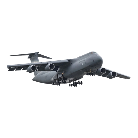
C-5M AIRCRAFT
(ATOS)
O
O
O
S
S
S
O
O
O
S
S
S
TO 1C-5M-2-1S-2
19 MAY 2017
O
O
O
S
S
S
O
O
S
S
O
S
O
S
O
S
O
S
O
S
O
S
O S
O
S
O
S
O
S
O
S
O
S
O
S
O
S
O
S
O
S
O
S
1
O
O
S
S

Advertisement

loading

Summary of Contents for Lockheed USAF Series

  • Page 1 TECHNICAL MANUAL MAINTENANCE ORGANIZATIONAL LEVEL GROUND HANDLING AND SERVICING USAF SERIES C-5M AIRCRAFT (ATOS) This publication supplements TO 1C-5M-2-1, dated 20 April 2017. Reference to this supplement will be made on the title page of the basic manual by personnel responsible for maintaining the publication in current status.
  • Page 2 TO 1C-5M-2-1S-2 1. Page xvi, LIST OF TIME COMPLIANCE TECHNICAL ORDERS of the basic manual is amended, as a result of TO 35D3-3-84-503, to add the following: TO No. Date Title 35D3-3-84-503 29 July 2016 Modification of C-5M Engine Handling System from Part Number A5441-20FRK to Final Configuration MA9441-20FJR 2.
  • Page 3 TECHNICAL MANUAL MAINTENANCE ORGANIZATIONAL LEVEL GROUND HANDLING AND SERVICING USAF SERIES C-5M AIRCRAFT (ATOS) This supplement supersedes Operational Supplement TO 1C-5M-2-1S-14, dated 20 November 2015. This publication supplements TO 1C-5M-2-1, dated 20 April 2017. Reference to this supplement will be made on the title page of the basic manual by personnel responsible for maintaining the publication in current status.
  • Page 4 TO 1C-5M-2-1S-1 3.14.6 Lavatory Servicing. (See Figure 3-34.) Crew lavatory is installed on the right side of the airplane aft of relief crew seats and forward of the galley. Troop compartment lavatory, consisting of two separate toilet units, is installed on forward right end of troop compartment (except on AF68-0213 and AF68-0216). A service truck capable of supplying fresh water is required to fill the water storage tank behind the crew galley between FS 844 and FS 864.
  • Page 5 TO 1C-5M-2-1S-1 CAUTION If the airplane is inactive and is to be exposed to freezing temperatures, drain the waste tank as soon as possible after flight termination. Pre-charge waste tank immediately prior to next scheduled flight. Failure to comply could cause serious damage to tank. Pre-charge the waste tank by adding 3 to 5 gallons of rinse water from the service truck.
  • Page 6 TO 1C-5M-2-1S-1 CAUTION The service truck waste suction pump must be off prior to closing ACFT waste tank drain valve. Failure to comply could result in damage to the airplane. Stop the waste truck suction pump after all water has been drained from waste line. Push the drain cable handle (6) fully in to close the waste tank drain valve.
  • Page 7 TO 1C-5M-2-1S-1 WARNING Ensure over flow vent area is clear. Failure to comply may cause injury to personnel and/or damage to equipment. Pump water from the service truck until water begins to flow out of the overflow vent (1) on the lower fuselage of the aircraft, then stop the flow of water from the service truck.
  • Page 8 TO 1C-5M-2-1S-1 NOTE Soaking allows for efficient vinegar saturation in the waste lines while also allowing the toilet bowl and flush valve disk to be soaked. It is very important that crushed ice is used because it will scrape away waste and mineral build-up.
  • Page 9 TO 1C-5M-2-1S-1 3.14.11 Lavatory Water Tank Disinfection. (See Figure 3-34.) Disinfect the water tank in accordance with the following instructions. Refer to Table 3-9 for materials and equipment required for lavatory water tank disinfection. CAUTION Use only fresh water to service the lavatory water tank. Do not use water/ MiraBowl Q mixture (blue water).
  • Page 10 TO 1C-5M-2-1S-1 Drain water tank in accordance with paragraph titled Water Tank Draining Procedure. Service water tank in accordance with paragraph titled Lavatory Water Tank Servicing. If electrical power is no longer required, disconnect the electrical power source from the airplane in accordance with paragraph titled Disconnecting External Electrical Power.
  • Page 11 TO 1C-5M-2-1S-1 3.16 PRESSURIZED WATER SYSTEM SERVICING (AF83-1285 AND UP). 15. Page 3-113 through page 3-115, Paragraph 3.16.1 through Paragraph 3.16.3 of the basic manual are amended, as a result of TO 1C-5M-544, to be deleted in their entirety. 16. Page 3-187, Figure 3-34, Crew Lavatory Waste Servicing (AF68-0213, AF68-0216, and AF69-0024) (Sheet 1 of 2) of the basic manual is amended, as a result of TO 1C-5M-544, to be replaced with page 12 of this supplement.
  • Page 12 TO 1C-5M-2-1S-1 Figure 1-21. Circuit Breaker Locations (Sheet 6)
  • Page 13 TO 1C-5M-2-1S-1 Figure 1-21. Circuit Breaker Locations (Sheet 13)
  • Page 14 TO 1C-5M-2-1S-1 Figure 3-34. Crew Lavatory Waste Servicing (AF68-0213, AF68-0216, and AF69-0024)
  • Page 15 TO 1C-5M-2-1S-1 Figure 3-34.1. Tank Cleaning Adapter...
  • Page 16 TO 1C-5M-2-1S-1 Figure 3-34.2. Toilet Maintenance Switch...
  • Page 17 SUPPLEMENTS MAINTENANCE ORGANIZATIONAL LEVEL GROUND HANDLING AND SERVICING USAF SERIES C-5M AIRCRAFT This revision supersedes TO 1C-5M-2-1, dated 17 February 2012. This publication incorporates Operational Supplements TO 1C-5M-2-1S-17, dated 15 March 2016, TO 1C-5M-2-1S-19, dated 21 April 2016, TO 1C-5M-2-1S-20, dated 5 May 2016, and TO 1C-5M-2-1S-24, dated 16 September 2016.
  • Page 18 TO 1C-5M-2-1 INSERT LATEST CHANGED PAGES. DESTROY SUPERSEDED PAGES. LIST OF EFFECTIVE PAGES NOTE The portion of the text affected by the changes is indicated by a vertical line in the outer margins of the page. Changes to illustrations are indicated by shaded or screened areas, or by miniature pointing hands.
  • Page 19 TO 1C-5M-2-1 TABLE OF CONTENTS Chapter Page LIST OF ILLUSTRATIONS ........... . . LIST OF TABLES .
  • Page 20 TO 1C-5M-2-1 TABLE OF CONTENTS - CONTINUED Chapter Page 1.5.2 Condition: Blowing Sand or Dust ......... . 1-33 1.5.3 Condition: Heavy Rain .
  • Page 21 TO 1C-5M-2-1 TABLE OF CONTENTS - CONTINUED Chapter Page 2.5.7 FS 524 and 1964 Jacking Adapter Removal ........2-28 2.5.8 FS 524 and FS 1964 Jacking Adapter Installation .
  • Page 22 TO 1C-5M-2-1 TABLE OF CONTENTS - CONTINUED Chapter Page 2.8.7 Aft Cargo Center Door Hoisting Procedure for Installation or Removal on the Airplane (AF69- 0024 and AF83-1285 and Up) ......... . 2-59 2.8.8 Aft Cargo Center Door Half Hoisting Procedure for Installation or Removal on the Airplane...
  • Page 23 TO 1C-5M-2-1 TABLE OF CONTENTS - CONTINUED Chapter Page 2.10.4 NLG and MLG Wheel Protective Cover ........2-71 2.10.5 APU Inlet Duct Protective Plug .
  • Page 24 TO 1C-5M-2-1 TABLE OF CONTENTS - CONTINUED Chapter Page 3.5.2 MLG Shock Strut De ation Procedure........3-41 3.5.3 MLG Shock Strut Primary (Upper) Chamber In ation Procedure .
  • Page 25 TO 1C-5M-2-1 TABLE OF CONTENTS - CONTINUED Chapter Page 3.14.5 Cleaning and Disinfecting the Crew Galley Potable Water System (AF68-0213, AF68-0216, and AF69-0024) ........... . 3-104 3.14.6 Crew Lavatory Servicing .
  • Page 26 TO 1C-5M-2-1 TABLE OF CONTENTS - CONTINUED Chapter Page LUBRICATION ............. Types of Lubrication.
  • Page 27 TO 1C-5M-2-1 LIST OF ILLUSTRATIONS Number Title Page Airplane Dimensions............1-42 Major Component Weights.
  • Page 28 TO 1C-5M-2-1 LIST OF ILLUSTRATIONS - CONTINUED Number Title Page 2-19 Wing Jacking Points ............2-99 2-20 Landing Gear Jacking Points .
  • Page 29 TO 1C-5M-2-1 LIST OF ILLUSTRATIONS - CONTINUED Number Title Page 2-74 APU Inlet Duct Protective Plug ..........2-171 2-75 APU Exhaust Duct Cover .
  • Page 30 TO 1C-5M-2-1 LIST OF ILLUSTRATIONS - CONTINUED Number Title Page 3-48 Cargo Winch (Part No. 4PF90020-101A) (AF83-1285 and Up) ......3-214 3-49 Upper Deck Floor Covering Repair .
  • Page 31 TO 1C-5M-2-1 LIST OF TABLES - CONTINUED Number Title Page Pressure ............. . . Torque .
  • Page 33 TO 1C-5M-2-1 INTRODUCTION 1 PURPOSE. This manual is one of a series of specialized maintenance manuals for the C-5M airplane. It provides the information necessary for ground handling and servicing at the organizational maintenance level. No instructions are included in this manual for maintenance which must be performed at the intermediate or depot maintenance levels.
  • Page 34 TO 1C-5M-2-1 3.4 Removal and Installation. Provides detailed instructions for the removal and installation of all line replaceable units if the procedure for the removal and installation of these units is not obvious. For those line replaceable units that can be removed and installed at the organizational level of maintenance, illustrations are provided locating each unit in the airplane.
  • Page 35 TO 1C-5M-2-1 Center Drive Unit Center of Gravity CMDS Cockpit Management Display System Direct Current Directional Control Valve Embedded Diagnostic System Electro Explosive Devices EPCR Electrical Power Control Rack ESDS Electrostatic Discharge Sensitive Fault Description Fault Isolation Fuselage Stations Fire Suppression System Integrated Drive Generator IRCM Infrared Countermeasures System...
  • Page 36 TO 1C-5M-2-1 Table 1. Approved Cleaning Solvents Cleaning Process Approved Solvents Prior to Painting Isopropyl Alcohol (TT-I-735) Methyl Isobutyl Ketone (ASTM D-1153) Prior to Sealing Aliphatic Naphtha (TT-N-95) Dry Cleaning Fluid (MIL-PRF-680, Type II or Type III) DS-108 (Commercial) Isopropyl Alcohol (TT-I-735) Shopmaster RC (Commercial) Prior to Adhesive Bonding Acetone (ASTM D-329)
  • Page 37 TO 1C-5M-2-1 SAFETY SUMMARY 1 GENERAL SAFETY INSTRUCTIONS. This manual describes physical and chemical processes which may cause injury or death to personnel, or damage to equipment if not properly followed. Comply with all warnings and cautions to prevent accidental injury to personnel or damage to equipment.
  • Page 38 TO 1C-5M-2-1 5.1 Maintenance Coordination. All coordination with the mechanics in the ight station, cargo compartment, center wing rear and front beams, and hydraulic and electrical power controls require a positive response that these mechanics properly understand the action to be taken; repeat back the action to be taken; and con rm that the action is complete. Failure to comply could cause injury to personnel.
  • Page 39 TO 1C-5M-2-1 • A radiation hazard exists when the color weather radar system is operated on the ground. The hazard area is a semicircle of 46-foot radius forward of the color weather radar antenna. Care must be taken to ensure that the exposed area up to 34 feet is clear of personnel and electro-explosive devices and the exposed area up to 46 feet is clear of any fueling operations before operating the color weather radar, and that the area remains clear during operation.
  • Page 41 TO 1C-5M-2-1 CHAPTER 1 GENERAL INFORMATION 1.1 GENERAL AIRPLANE INFORMATION. 1.1.1 Airplane Description. The Model C-5 airplane is a high-speed, long-range, high sweptback wing, T-tailed mono- plane. The airplane is designed for transportation of general cargo, wheeled vehicles, or palletized cargo for aerial delivery. It is adaptable to personnel transportation and can accommodate 75 troops in the troop compartment, 270 troops in the cargo compartment when the palletized seat kit is installed, 8 persons in the troop/courier compartment, 7 persons in the relief crew compartment, and a maximum of 7 ight crew personnel in the ight deck.
  • Page 42 TO 1C-5M-2-1 no-step areas. The walkways are selected for the structural capability to withstand more weight than other areas. The walkway areas are clearly marked on the airplane. Do not walk or step in an area that is not designated as a walkway. The no-step areas are so designated because the structure is not designed to withstand a person’s weight.
  • Page 43 TO 1C-5M-2-1 Area Classification Radome Plug Access Wing Tip Access (R&R) NOTE: PR = Permit Required, NPR = Non-Permit 1.1.10 Access Provisions. (See Figure 1-7 through Figure 1-13.) Required access doors and panels are provided through- out the airplane for easy access to critical areas, ller caps, drain valves, test connections, etc. These doors and panels are secured with various types of fasteners which range from screws to spring-loaded hinges, depending upon the location and use of the door or panel.
  • Page 44 TO 1C-5M-2-1 Table 1-1. Metric Conversion Data - Continued No. Of Multiplied By Equals No. Of Pounds per square foot 04.882 Kilograms per square meter TORQUE Inch-pounds 1.153 Centimeters-Kilograms Foot-pounds 0.138 Meter-Kilograms FLOW RATE Gallons per minute 3.785 Liters per minute VELOCITY Feet per second 0.305...
  • Page 45 TO 1C-5M-2-1 Table 1-3. Area - Continued Square Inches = Square Centimeters Square Feet = Square Meters 387.120 5.580 451.680 6.510 516.160 7.440 580.680 8.370 645.200 9.300 Table 1-4. Volume Cubic Inches = Cubic Centimeters Cubic Feet = Cubic Meters 16.387 0.028 32.774...
  • Page 46 TO 1C-5M-2-1 Table 1-5. Liquid Capacity - Continued Ounces = Millimeters = Liters Pints = Liters Quarts = Liters Gallons = Liters 2,365.920 2.366 37.840 75.680 302.800 2,661.660 2.662 42.570 85.140 340.650 2,957.400 2.957 47.300 94.600 378.500 Table 1-6. Weight Ounces = Grams Pounds = Kilograms 28.350...
  • Page 47 TO 1C-5M-2-1 Table 1-7. Temperature - Continued °F = °C °F = °C °F = °C 4.448 204.608 10.008 260.208 Table 1-8. Pressure Pounds Per Square Inch = Kilograms Per Square Centime- Pounds Per Square Foot = Kilograms Per Square Meter 0.700 4.882 1.400...
  • Page 48 TO 1C-5M-2-1 Table 1-9. Torque - Continued Inch-Pounds = Centimeter Kilograms Foot-Pounds = Meter Kilograms 115.300 13.800 Table 1-10. Flow Rate Gallons Per Minute = Liters Per Minute Gallons Per Minute = Liters Per Minute 3.785 37.850 7.570 56.775 11.355 75.700 15.140 94.625...
  • Page 49 TO 1C-5M-2-1 1.3 GENERAL MAINTENANCE INFORMATION. (Not applicable to AF68-0213 and AF68-0216) Uninsulated LN2 tubing is located in the cargo compartment ceiling area from FS1420 to FS1490, LBL105 to RBL140. Under certain operational conditions the temperatures generated by LN2 ow internal to the tubing can cause cryogenic material to accumulate on the external surface of the tubing.
  • Page 50 TO 1C-5M-2-1 Failure to comply with Step a and Step b could result in injury to personnel. NOTE Any item noted in Step a and Step b which affects proper use of harness will be cause to reject harness assembly as unserviceable.
  • Page 51 TO 1C-5M-2-1 • Failure to secure a safety strap to the airplane before attempting to get on top of the airplane could result in falling off while attempting to get on top of the airplane or while attempting to secure the safety strap to the airplane.
  • Page 52 TO 1C-5M-2-1 (4) Place clevis (4) onto aft fan case attachment point (6). (5) Insert pin (2) into clevis (4) and aft fan case attachment point (6). (6) Install safety pin (3) with streamer (1) attached. (7) Attach self-locking hook of lanyard to hoist ring (5). b.
  • Page 53 TO 1C-5M-2-1 b. Use the following procedures to remove the personal fall protection devices and safety web strap (7) from quadrapod attach point (1, 2): (1) Remove lifeline lanyard snap hook (3) from safety web strap D ring (6). (2) Remove safety web strap (7) from quadrapod truss (1, 2). 1.3.5 Performing Maintenance Using a Workstand.
  • Page 54 TO 1C-5M-2-1 On airplanes modi ed by TO 1C-5-799, IRCM GROUND TEST switch must in NORMAL and IRCM GND light is ON to prevent accidental IRCM system activation. Failure to comply may result in injury to personnel or damage to equipment. NOTE IRCM GND light will only be ON when Core Power is applied.
  • Page 55 TO 1C-5M-2-1 Before external power is applied to the airplane, APU battery must have a charge of no less than 22.5 volts. If voltage is less than 22.5 volts, replace battery in accordance with TO 1C-5M-2-7-1, Chapter 3. Failure to comply could result in damage to equipment or airplane.
  • Page 56 TO 1C-5M-2-1 • SPIN UP 1 • SPIN UP 2 (3) Flight Engineer Panel No. 2, BATTERY BUS • SAI BACKUP (4) Flight Engineer Panel No. 3, FWD MAIN AC BUS NO. 3 • CASTER/PWR BACK CONTR BOX PWR • CASTER/PWR BACK MON LVDT PWR (5) Flight Engineer Panel No.
  • Page 57 TO 1C-5M-2-1 When outside temperature is above 60 °F, do not connect external electrical power to the airplane for more than 15 minutes with the EXT PWR switch OFF and AVAIL light on. Failure to comply will result in inoperative Electrical Power Control Rack (EPCR) cooling fans and damage to the Bus Power Control Unit (BPCU) may occur if no other electrical power is applied to the airplane.
  • Page 58 TO 1C-5M-2-1 NOTE APU BATTERY ISO CONTACTOR CLOSED light will be defaulted to NVIS (very dim) until core processing system power is applied. ag. Place APU BATTERY CHARGER switch (1) to BYPASS. DC VOLTS meter should indicate a steady 28 (±3) volts. Ensure APU BATTERY ISO CONTACTOR CLOSED light (2) comes on.
  • Page 59 TO 1C-5M-2-1 • VIA 1 FAN • AIU 1 FAN • VIA 2 FAN ALT • AIU 2 FAN ALT (2) Pilot emergency circuit breaker panel, EMER DC BUS • VIA 2 ALT • AIU 2 ALT (3) Pilot emergency circuit breaker panel, EMERGENCY DC BUS •...
  • Page 60 TO 1C-5M-2-1 • PILOT RIGHT MFDU • PILOT MCDU • COPILOT CENTER MFDU (9) Navigator circuit breaker panel No. 1, AVIONICS DC BUS 1 • AVIONICS DC BUS 1A (10) Navigator circuit breaker panel No. 1, AVIONICS ISO AC BUS PH A •...
  • Page 61 TO 1C-5M-2-1 • NAV MFDU (if installed) • NAV CCP (if installed) • NAV MCDU (if installed) (17) Navigator circuit breaker panel No. 2, AVIONICS DC BUS 2A • VIA 2 • AIU 2 • COPILOT CCD • COPILOT CNP •...
  • Page 62 TO 1C-5M-2-1 NOTE The Multifunction Display Unit (MFDU) default displays are as follows: Pilot Left - Nav Display Pilot Center - PFD Display Pilot Right - ATC Com Display Copilot Left - Engine Format Copilot Center - PFD Display Copilot Right - NAV Display Flight Engineer - FE Engine Format Navigator - Nav Display (provisional) h.
  • Page 63 TO 1C-5M-2-1 • AIU 1 OVERTEMP • VIA 2 OVERTEMP • AIU 2 OVERTEMP • AIU 1 SYNC FAIL • AIU 2 SYNC FAIL • BACKUP MODE • BIP OVERTEMP • FMS FAIL • CCDL FAULT (2) Advisories - White: •...
  • Page 64 TO 1C-5M-2-1 p. Close the following circuit breakers. • AMC POWER - ight engineer circuit breaker panel No. 3, FWD MAIN AC BUS NO. 4 • PCIU - ight engineer circuit breaker panel No. 5, MAIN DC BUS NO. 2 q.
  • Page 65 TO 1C-5M-2-1 ad. On PCIU, select AUXILIARY BUS tab. ae. Con rm that Chan Status indicates Good for both Channel A and Channel B by verifying 1553 status of AMC. af. On PCIU, select EDS STATUS tab. ag. Con rm that AMC Bus Monitor Status indicates Active Channel A and B for Pilot Bus, Copilot Bus, Left US Bus, and Right US Bus.
  • Page 66 TO 1C-5M-2-1 Prior to disconnecting external electrical power, ensure that all ight control switches on pilot overhead panel are in NORM or AUTO, as required, except that INBD ELEVATOR LEFT SYS 3 and RIGHT SYS 2 are in OFF. Failure to comply could result in damage to the airplane. a.
  • Page 67 TO 1C-5M-2-1 Step g must be followed carefully. Failure to comply will result in damage to the airplane. g. Carefully line up the external power cart plug with the airplane receptacle (8). Place the plug directly on the receptacle. Do not wiggle or twist the plug. h.
  • Page 68 TO 1C-5M-2-1 Before connecting external pneumatic power, ensure that a warning tag is not attached to the external pneumatic receptacle. Failure to comply could cause injury to personnel. a. Obtain the A/M32A-60 (or equivalent) power cart. b. Remove the dust cover from the airplane pneumatic receptacle. c.
  • Page 69 TO 1C-5M-2-1 Prior to pressurizing any hydraulic system, ensure that all personnel and equipment are clear of ight control surfaces, ight control actuation mechanisms, landing gear doors, and landing gear actuation mechanisms. When pressure is applied, aps and slats move to the position selected by the control handle; aileron, elevator, and spoiler surfaces snap to neutral;...
  • Page 70 TO 1C-5M-2-1 Table 1-12. Tools and Test Equipment Required - Continued Figure and In- Nomenclature An Type Designation or Alternate Use and Application dex No. Part No. Radio Set NSN 5820-00-034-7403 Used for communication between crew members of the truck- mounted spraying unit 1.4.1 Safety Precautions.
  • Page 71 TO 1C-5M-2-1 b. To prevent damage to thin aluminum skins or honeycomb surfaces, keep the spray nozzle at least 10 feet away from the surface being sprayed. Position the anti-ice, deice spray at a direct contact angle of 45 degrees or less to minimize the impact pressure on the surface being sprayed.
  • Page 72 TO 1C-5M-2-1 b. Anti-ice, deice uid should be applied in a ne spray pattern and not in a solid ooding stream, to prevent excessive drainage and uid waste. c. At the completion of spraying operations, all lines must be ushed with cold uid to prevent damage due to freezing. 1.4.3 Anti-Icing, Deicing, and Snow and Frost Removal Procedures.
  • Page 73 TO 1C-5M-2-1 OFF, gust lock protection is not available. To prevent possible damage to the ight control surfaces, ensure that all ight control switches on the pilot overhead panel are left in NORM or AUTO, as required, except that INBD ELEVATOR LEFT SYS 3 and RIGHT SYS 2 are in OFF.
  • Page 74 TO 1C-5M-2-1 (3) Set temperature controls to AUTO and COOL. (4) For AF69-0024 and AF83-1285 and up, close troop compartment valve. (5) Open all gasper nozzles. (6) Close all compartment doors, hatches, and windows. b. For AF69-0024 and AF83-1285 and up, after 20 to 30 minutes of operation, the forward upper deck should be cooled sufficiently to open up the troop compartment valve.
  • Page 75 TO 1C-5M-2-1 1.5.5.3 External Electrical Power. Before connecting external electrical power at temperatures of -45 °F (-43 °C) and below, apply heat to the bus protection panel in the aft load center for 15 minutes. 1.5.5.4 Batteries. If airplane is exposed to temperatures below -15 °F (-26 °C) for more than 1 hour or temperatures below 0 °F (-18 °C) for more than 4 hours, remove aircraft and APU batteries and store in heated, protected area.
  • Page 76 TO 1C-5M-2-1 1.5.5.6 Engines. • Engine heat on shutdown melts ice accumulated during ight and the resulting moisture will refreeze in the lower sections of the front stator and rotor blades. An attempted engine start may result in starter failure. If engine is not free to rotate, external heat must be applied to forward engine sections to produce thawing.
  • Page 77 TO 1C-5M-2-1 The electric suction boost pump must be on for a minimum of 1 minute prior to starting the ATM and must remain on during operation. Failure to do so will damage the hydraulic pump. b. When operating the ATM at temperatures of -40 °F (-40 °C) and below, hydraulic pressure surges may be encountered. Pressure surges can be avoided or reduced to an acceptable level by using the following procedure: (1) Operate electric suction boost pumps for hydraulic systems 1 and 4 for at least 10 minutes prior to starting the ATM.
  • Page 78 TO 1C-5M-2-1 1.5.5.14 Airplane Surfaces. During freezing weather, movement along the top surfaces of the airplane may be hazardous due to frost or ice patches which may not be visible. Remove frost and ice in accordance with paragraph title Anti-Icing, Deicing, and Snow and Frost Removal.
  • Page 79 TO 1C-5M-2-1 1.5.5.22 Starter Air Valve. If cold temperatures prevent opening of the starter air valve, the valve can be opened manually by inserting an extension through an access hole in the bottom of the engine cowl into the 3/8-inch manual override socket drive built into the valve.
  • Page 80 TO 1C-5M-2-1 b. The systems should be operated under automatic control. Automatic control provides the maximum available duct air temperature during warm-up and allows compartment temperature to stabilize with a minimum of overshoot. If manual control is used, control valves are driven fully open, and the duct overheat switch may trip and drive the control valves closed.
  • Page 81 TO 1C-5M-2-1 LH TORQUE BOX NO. 6 SQUIB Main DC No. 1 Flight Engineer No. 6 LOGIC POWER Main DC No. 1 Flight Engineer No. 6 CDU POWER Main DC No. 1 Flight Engineer No. 6 RH FORWARD SQUIB Main DC No. 1 Flight Engineer No.
  • Page 82 TO 1C-5M-2-1 Figure 1-1. Airplane Dimensions 1-42...
  • Page 83 TO 1C-5M-2-1 Figure 1-2. Major Component Weights (Sheet 1 of 3) 1-43...
  • Page 84 TO 1C-5M-2-1 Figure 1-2. Major Component Weights (Sheet 2) 1-44...
  • Page 85 TO 1C-5M-2-1 Figure 1-2. Major Component Weights (Sheet 3) 1-45...
  • Page 86 TO 1C-5M-2-1 Figure 1-3. Airplane Stations (Sheet 1 of 8) 1-46...
  • Page 87 TO 1C-5M-2-1 Figure 1-3. Airplane Stations (Sheet 2) 1-47...
  • Page 88 TO 1C-5M-2-1 Figure 1-3. Airplane Stations (Sheet 3) 1-48...
  • Page 89 TO 1C-5M-2-1 Figure 1-3. Airplane Stations (Sheet 4) 1-49...
  • Page 90 TO 1C-5M-2-1 Figure 1-3. Airplane Stations (Sheet 5) 1-50...
  • Page 91 TO 1C-5M-2-1 Figure 1-3. Airplane Stations (Sheet 6) 1-51...
  • Page 92 TO 1C-5M-2-1 Figure 1-3. Airplane Stations (Sheet 7) 1-52...
  • Page 93 TO 1C-5M-2-1 Figure 1-3. Airplane Stations (Sheet 8) 1-53...
  • Page 94 TO 1C-5M-2-1 Figure 1-4. Danger Areas (Sheet 1 of 17) 1-54...
  • Page 95 TO 1C-5M-2-1 Figure 1-4. Danger Areas (Sheet 2) 1-55...
  • Page 96 TO 1C-5M-2-1 Figure 1-4. Danger Areas (Sheet 3) 1-56...
  • Page 97 TO 1C-5M-2-1 Figure 1-4. Danger Areas (Sheet 4) 1-57...
  • Page 98 TO 1C-5M-2-1 Figure 1-4. Danger Areas (Sheet 5) 1-58...
  • Page 99 TO 1C-5M-2-1 Figure 1-4. Danger Areas (Sheet 6) 1-59...
  • Page 100 TO 1C-5M-2-1 Figure 1-4. Danger Areas (Sheet 7) 1-60...

This manual is also suitable for:

C-5m