
Summary of Contents for MFC SPEED CREED
- Page 1 ROLLER SCREED OPERATION & PARTS MANUAL 3334 North Booth Street, Milwaukee WI 53212 U.S.A. 414.964-4550 I REV.03 414-964-4503 EMAIL: info@metalforms.com I WEBSITE:...
- Page 3 Metal Forms Corporation (MFC). MFC assumes no responsibility or liability for any errors or inaccuracies that may appear in this manual.
-
Page 4: Table Of Contents
Table of Contents Table of Contents ............................................... 2 Manual Information ..............................................4 Serial Number Identification ............................................5 Spare/Replacement Parts Ordering Information ....................................... 6 Machine Specifications .............................................. 7 MACHINE ................................................7 HYDRAULIC SYSTEM ............................................7 ROLLER/SLINGER TUBES ..........................................7 SUPPORT FRAMES ............................................7 SPRAY SYSTEM .............................................. - Page 5 Hydraulics Assembly – Pump/Motors ........................................ 34 Hydraulics Assembly – Pump/Filter/Manifold/Cooler/Tank ................................35 Hydraulics Assembly – Pump/Filter/KS Manifold/Kick Stand ................................36 Hydraulics Assembly –Kick Stand ........................................37 Hydraulics Assembly – Tandem Pump ......................................38 Hydraulics Assembly – Proportional Control Manifold..................................39 Hydraulics Assembly –...
-
Page 6: Manual Information
Manual Information This manual is meant to provide safety, operation, and maintenance procedures for your Speed Screed Roller machine. For your own safety and protection from personal injury, carefully read, understand, and observe the safety instructions described in the following sections. Keep this manual with the machine at all times. -
Page 7: Serial Number Identification
Serial Number Identification If you need to order parts, you will be asked for your machine serial number. The serial number found on the identification plate is a twelve-digit number and corresponds to the below breakdown: R-121381-03-19-1 R – Roller Screed Order Year Month... -
Page 8: Spare/Replacement Parts Ordering Information
Spare/Replacement Parts Ordering Information The Parts section of this manual gives detailed assembly drawings and Bill of Materials (BOMs) to aid in finding replacement parts for your machine. Please note that all the information, specifications, and illustrations in this manual are subject to change without notice and are based on the latest information available at the time of printing. -
Page 9: Machine Specifications
Machine Specifications MACHINE Machine weight (15’): 3,537 lbs. [1604kg] Approximate weight per foot for additions: 119 lbs. [54kg] Hydraulic Oil Reservoir (ISO 46): 10 gallons [37.85L] Available machine lengths (in 1’ increments): 10’-30’ [3m-9.1m] Fuel Reservoir: 12 gal. [45.42L] HYDRAULIC SYSTEM Hydraulic motor attachment to each tube: Direct drive via keyed bushing &... -
Page 10: Engine Specifications
Engine Specifications HONDA GX690 22hp V-TWIN Engine Type Air-cooled 4-stroke OHV Bore x Stroke 78 mm X 72 mm Displacement 42 in [688 cm Net Power Output* 22.1 bhp [16.5 kW] @ 3,600 rpm Net Torque 35.6 lb-ft [48.3 Nm] @ 2,500 rpm PTO Shaft Rotation Counterclockwise [from PTO shaft side] Compression Ratio... -
Page 11: Engine Wiring Diagram
Engine Wiring Diagram 26A CHARGING SYSTEM REV.03_9/2021... -
Page 12: Machine Dimensions
Machine Dimensions REV.03_9/2021... -
Page 13: Safety Section
SAFETY Safety Section State/Federal Regulations REV.03_9/2021... -
Page 14: Safety Information
SAFETY Safety Information Make sure to read this manual in its entirety BEFORE operation or servicing of this machine. Safety precautions must be followed at all times when operating this equipment. Failure to read and understand the safety messages and operating instructions could result in injury to yourself and others. -
Page 15: Safety Symbols
SAFETY Safety Symbols Potential hazards associated with the operation of this equipment will be referenced with hazard symbols which may appear throughout this manual in conjunction with safety notes. SYMBOL SAFETY HAZARD Lethal exhaust gas hazards Explosive fuel hazards Burn hazards Rotating parts hazards Crush hazards Hydraulic fluid hazards... -
Page 16: General Safety Guidelines
SAFETY NOTICE General Safety Guidelines • Operator concentration is always an important factor when using mechanical equipment and anything that distracts the operator during operation is a clear and present danger. • Familiarity and proper training are required for the safe operation of all Metal Forms Corporation™... - Page 17 SAFETY CAUTION • NEVER touch the hot exhaust manifold, muffler, or cylinder. Allow these parts to cool before servicing equipment. NOTICE • NEVER run engine without an air filter or with a dirty air filter. Severe engine damage may occur. Service air filter frequently to prevent engine malfunction. •...
- Page 18 SAFETY DANGER • DO NOT drop the battery. There is a possibility that the battery will explode. • DO NOT expose the battery to open flames or sparks. The battery contains combustible gases and liquids. If these gases and liquids come in contact with a flame or spark, an explosion could occur.
- Page 19 SAFETY CAUTION • ALWAYS disconnect the negative battery terminal before performing service on the equipment. • ALWAYS keep battery cables in good working condition. Repair or replace all worn cables. • Walk around the machine before starting it to see if any items are worn, damaged, leaking, etc.
-
Page 20: Machine Operation
OPERATION Machine Operation Machine Basics The Speed Screed™ Roller (SSR) is a variable length triple tube roller system that allows users to easily swap rollers and extension frames between jobs that require different pour widths. With rollers and extensions available from 10’ to 30’ in single foot increments, almost any job can be easily handled with this machine. -
Page 21: Startup Procedure
OPERATION Startup Procedure NOTICE BEFORE you start the machine, refer to the images on the following page for location and identification of the operational and visual controls pertaining to the operation of the machine. Once you have identified all locations, check the following prior to start-up: 1. -
Page 22: Controls/Features
OPERATION Controls/Features Horn Hydraulic Oil Spray Kickstand Slinger On/Off Fill Cap On/Off Drive Control Lever Lever Hour Hydraulic Oil Meter Level Indicator Ignition Throttle Engine Control Oil Light Fuse Fuel Tank Block Owner’s On/Off Manual Engine Oil Dipstick/Fill Fuel Gauge Hydraulic Oil Filter REV.03_9/2021... -
Page 23: Machine Operation
OPERATION Machine Operation Starting Machine Operation 1. Once you have followed the Startup Procedure outlined above, increase the throttle to approximately 80%-90% of the maximum RPM. NOTE: The machine should never be in operation with the throttle set less than 75%. 2. -
Page 24: Service & Adjustments
SERVICE Service & Adjustments Height Adjustment on Slinger The front slinger roller tube is adjustable from 0”-1” [0-25mm] above the drive rollers. In order to adjust how much concrete passes under this roller follow the procedure listed below. 1. Loosen the (4) 3/8” nuts/bolts on the hydraulic motor (A) and the (2) 3/8” nuts/bolts on the idler side bearing (B). -
Page 25: Changing Length & Tubes
SERVICE Changing Length & Tubes Each of the three rollers utilize a bolting flange and are symmetrical which makes changing machine length quick and easy. The rollers can be orientated in either direction and can be mounted in any position. To replace or swap roller lengths follow the below procedures. 1. -
Page 26: Maintenance
SERVICE Maintenance Below is an outline of general machine maintenance schedule. Please refer to your Honda Owner’s Manual for a complete list of engine maintenance recommended by the manufacturer. Daily Maintenance Spray form release oil on any surfaces that will be in contact with concrete Check for loose roller connection hardware Check fuel level Check engine oil level... -
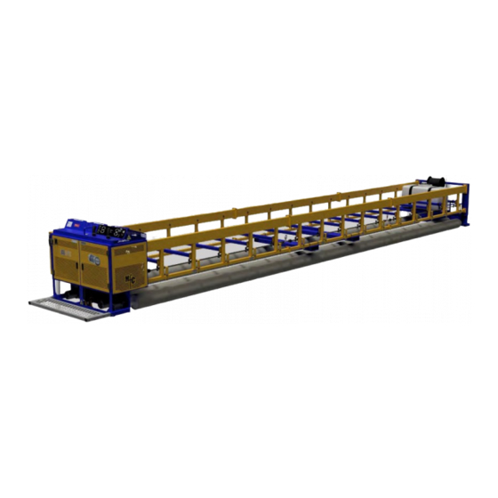
Page 27: Parts
PARTS Parts Full Assembly Full Assembly – BOM REV.03_9/2021... -
Page 28: End Frame - Power Assembly
PARTS End Frame – Power Assembly REV.03_9/2021... -
Page 29: End Frame - Power Assembly (Continued)
PARTS End Frame – Power Assembly (Continued) REV.03_9/2021... -
Page 30: End Frame - Power Assembly Bom
PARTS End Frame – Power Assembly BOM END FRAME - POWER ASSEMBLY PART LIST (780-204) ITEM QTY PART NUMBER DESCRIPTION PAGE# 780-204.1 END FRAME WELDMENT, POWER, RS 780-204.2 ENGINE ASSEMBLY, 22HP HONDA iGX700 29-30 780-204.3 HYDRAULIC SYSTEM ASSEMBLY 31-36 780-204.4 FUEL SYSTEM ASSEMBLY 27-38 780-204.5... -
Page 31: Engine Assembly
PARTS Engine Assembly REV.03_9/2021... -
Page 32: Engine Assembly Bom
PARTS Engine Assembly BOM ENGINE ASSEMBLY PARTS LIST (780-204.2) ITEM QTY PART NUMBER DESCRIPTION 780-63 ENGINE ASSEMBLY, 22HP HONDA, IGX700 ROLLER SCREED 780-63.1 ENGINE, 22.0 H.P. HONDA iGX700 780-63.2 SIZE 18 PMM SAE "A" 2-BOLT, 5-3/4" ENG PILOT, 6.5" BCD 780-63.3 28/38 PM "B"... -
Page 33: Hydraulics Assembly
PARTS Hydraulics Assembly REV.03_9/2021... -
Page 34: Hydraulics Bom
PARTS Hydraulics BOM HYDRAULIC ASSEMBLY PARTS LIST (780-204.3) ITEM QTY PART NUMBER DESCRIPTION PAGE# 780-204.3.1 TANK, HYDRAULIC, 10gal. 780-204.3.2 KICKSTAND ASSEMBLY 780-274.3.3 PUMP, TANDEM ASSY, w/ FITTINGS 780-274.3.4 PROPORTIONAL CONTROL MANIFOLD ASSEMBLY 780-274.3.5 HYDRAULIC MOTOR ASSEMBLY 780-274.3.6 HYDRAULIC COOLER ASSEMBLY 780-274.3.7 HYDRAULIC MANIFOLD, KICKSTAND 780-274.3.8... -
Page 35: Hydraulic Assembly - Tank
PARTS Hydraulic Assembly - Tank ITEM QTY PART NUMBER DESCRIPTION 780-204.3.1.1 HYDRAULIC TANK WELDMENT, 10gal. 780-274.3.1.2 FILLER BREATHER CAP, 3/4" NPT 780-274.3.1.3 HYDRAULIC OIL LEVEL & TEMP GAUGE 780-274.3.1.4 SUCTION STRAINER, TANK MOUNTED, 1-1/2" TO 1" NPT 020-485 SCREW, CAP, HEX HEAD, 3/8"-16 X 1", GR.A, FT, ZPS 780-274.3.1.6 FITTING, HYD, STRAIGHT NPT-JIC, 6-8 780-255... -
Page 36: Hydraulics Assembly - Pump/Motors
PARTS Hydraulics Assembly – Pump/Motors ITEM QTY PART NUMBER DESCRIPTION 780-274.3.3 PUMP, TANDEM ASSY, w/ FITTINGS 780-274.3.5 HYDRAULIC MOTOR ASSEMBLY 780-274.3.23 HOSE ASSEMBLY, MOTOR-DRIVE-1 (A) - PUMP (A2) 780-274.3.24 HOSE ASSEMBLY, MOTOR-DRIVE-1 (B) - MOTOR-DRIVE-2 (A) 780-274.3.25 HOSE ASSEMBLY, MOTOR-DRIVE-2 (B) - PUMP (B2) 780-274.3.26 HOSE ASSEMBLY, MOTOR-SLINGER (B) - PUMP (A1) 780-274.3.27... -
Page 37: Hydraulics Assembly - Pump/Filter/Manifold/Cooler/Tank
PARTS Hydraulics Assembly – Pump/Filter/Manifold/Cooler/Tank ITEM QTY PART NUMBER DESCRIPTION 780-204.3.1 TANK, HYDRAULIC, 10gal. 780-274.3.3 PUMP, TANDEM ASSY, w/ FITTINGS 780-274.3.4 PROPORTIONAL CONTROL MANIFOLD ASSEMBLY 780-274.3.6 HYDRAULIC COOLER ASSEMBLY 780-274.3.8 FILTER ASSEMBLY 780-274.3.14 HOSE ASSEMBLY, FILTER (OUT-2) - PILOT (P) 780-274.3.18 HOSE ASSEMBLY, PILOT (T) - TANK (2) 780-274.3.19... -
Page 38: Hydraulics Assembly - Pump/Filter/Ks Manifold/Kick Stand
PARTS Hydraulics Assembly – Pump/Filter/KS Manifold/Kick Stand ITEM QTY PART NUMBER DESCRIPTION 780-204.3.2 KICKSTAND ASSEMBLY 780-274.3.3 PUMP, TANDEM ASSY, w/ FITTINGS 780-274.3.6 HYDRAULIC COOLER ASSEMBLY 780-274.3.7 HYDRAULIC MANIFOLD, KICKSTAND 780-274.3.8 FILTER ASSEMBLY 780-274.3.10 CLAMP, TIGHT SEAL, BOLT, 1-3/8"-1-1/2"ID 780-274.3.11 HOSE ASSEMBLY, CHARGE PUMP (IN) - TANK (OUT) 780-274.3.12 HOSE ASSEMBLY, CHARGE PUMP (OUT) - FILTER (IN) 780-274.3.13... -
Page 39: Hydraulics Assembly -Kick Stand
PARTS Hydraulics Assembly –Kick Stand ITEM QTY PART NUMBER DESCRIPTION 780-249 HYDRAULIC CYLINDER, 2-1/2" BORE, 16" STROKE 780-204-3.2.2 KICKSTAND, FOOT ASSEMBLY 046-675 CLEVIS PIN, 1" X 4-1/2", ZPS 046-215 COTTER PIN, 3/16" x 1-3/4", ZPS 780-274.3.2.5 FITTING, HYD, 90 DEG, ORB-JIC, 6-8 014-290 PIPE. -
Page 40: Hydraulics Assembly - Tandem Pump
PARTS Hydraulics Assembly – Tandem Pump ITEM QTY PART NUMBER DESCRIPTION 780-274.3.3.1 PUMP, BONDIOLI, TANDEM 780-274.3.3.6 FITTING, HYD, 37 DEG. FLARE, JIC SWIVEL, 90DEG, 4-4 780-274.3.3.3 FITTING, HYD, STRAIGHT ORB-JIC, 8-8 780-274.3.3.8 FITTING, HYD, 90 DEG. ORB, JIC, 8 780-274.3.3.7 FITTING, HYD, LOW PRESSURE BEADED INSERT, 12-16 780-274.3.7.9 FITTING, HYD, 90 DEG, ORB-JIC, 8-10... -
Page 41: Hydraulics Assembly - Proportional Control Manifold
PARTS Hydraulics Assembly – Proportional Control Manifold ITEM QTY PART NUMBER DESCRIPTION 780-204.3.4.1 PROP MANIFOLD RISER PLATE 780-274.3.4.2 THOMAS MAGNETE PROPORTIONAL CONTROL BLOCK 780-274.3.4.3 FITTING, HYD, STRAIGHT ORB-JIC, 4 780-274.3.4.4 FITTING, HYD, STRAIGHT ORB-JIC, 6 780-274.3.4.5 FITTING, HYD, 90 DEG. ORB, JIC, 6 780-274.3.3.6 FITTING, HYD, 37 DEG. -
Page 42: Hydraulics Assembly - Motor
PARTS Hydraulics Assembly – Motor ITEM QTY PART NUMBER DESCRIPTION 780-077 HYDRAULIC MOTOR, ROLLER SCREED, PARKER-TF-LSHT 780-274.3.3.4 FITTING, HYD, STRAIGHT ORB-JIC, 8-10 020-532 SCREW, CAP, HEX HEAD, 1/2"-13x3-1/4", GR.5, ZPS 040-150 NUT, HEX, 1/2"-13, GR.5, ZPS REV.03_9/2021... -
Page 43: Hydraulics Assembly - Hydraulic Cooler
PARTS Hydraulics Assembly – Hydraulic Cooler ITEM QTY PART NUMBER DESCRIPTION 780-204.3.6.1 HYDRAULIC COOLER BRACKET, R 780-204.3.6.2 HYDRAULIC COOLER BRACKET, L 780-204.3.6.3 HYDRAULIC OIL HEAT EXCHANGER 780-204.3.6.4 FITTING, HYD, STRAIGHT ORB-JIC, 8-16 020-906 SCREW, CAP, HEX HEAD, M8-1.25 X 12mm, FT, ZPS REV.03_9/2021... -
Page 44: Hydraulics Assembly - Kickstand Manifold
PARTS Hydraulics Assembly – Kickstand Manifold ITEM QTY PART NUMBER DESCRIPTION 780-274.3.7.1 MANIFOLD, DAMAN, STD. FLOW, PARALLEL, ASSEMBLY 780-274.3.7.3 PRESSURE RELIEF VALVE, ARGO-HYTOS 780-274.3.7.6 FITTING, HYDRAULIC, PLUG, -10 780-274.3.3.4 FITTING, HYD, STRAIGHT ORB-JIC, 8-10 780-274.3.7.9 FITTING, HYD, 90 DEG, ORB-JIC, 8-10 780-274.3.7.7 FITTING, HYD, STRAIGHT ORB-JIC, 6-8 780-274.3.7.2... -
Page 45: Hydraulics Assembly - Filter
PARTS Hydraulics Assembly – Filter ITEM QTY PART NUMBER DESCRIPTION 780-274.3.8.1 FILTER, HYDRAULIC, MEDIUM PRESSURE 780-274.3.8.2 FITTING, HYD, STRAIGHT ORB-JIC, 8-12 780-256 SPACER, ALUMINUM, 5/16" ID x 3/4" OD x 1/2" LONG 022-313 SCREW, MACHINE, 5/16"-18 x 1", PHP, FH, ZPS 780-274.3.8.5 FITTING, HYD, TEE, ORB-JIC, 8-12-8 780-274.3.8.6... -
Page 46: Fuel System Assembly
PARTS Fuel System Assembly REV.03_9/2021... -
Page 47: Fuel System Bom
PARTS Fuel System BOM FUEL SYSTEM PARTS LIST (780-204.4) ITEM QTY PART NUMBER DESCRIPTION 780-259.1 12 GALLON CARB ASSY KIT 780-259.1.1 TANK, FUEL, 12gal. 780-259.1.2 FUEL GAUGE WITH SEAL (INSTALLED) 780-259.1.3 FUEL CAP, 12 GAL. (INSTALLED) 780-259.1.4 FUEL FITTING, 1/4" ROV (INSTALLED) 780-259.1.5 TANK, STRAPS, 12GAL. -
Page 48: Battery Assembly
PARTS Battery Assembly Battery BOM BATTERY ASSEMBLY PARTS LIST ITEM QTY PART NUMBER DESCRIPTION 780-230 BATTERY, 12V, ROLLER SCREED 780-261 LARGE-CELL BATTERY HOLD-DOWN 780-263 BATTERY TERMINAL, MIL SPEC, TOP POST SET w/ COVER 780-264 BATTERY CABLE, 6' X 4AWG, 3/8" RING TERMINALS 043-002 CABLE TIE, 6"... -
Page 49: End Frame - Control Panel Assembly
PARTS End Frame – Control Panel Assembly REV.03_9/2021... -
Page 50: End Frame - Control Panel Bom
PARTS End Frame – Control Panel BOM CONTROL PANEL ASSEMBLY PARTS LIST ITEM QTY PART NUMBER DESCRIPTION 780-204.6.1 CONTROL PANEL WELDMENT 780-204-6.2 CONTROL PANEL, GUSSET 580-930 SERIAL NO. PLATE "SPEED SCREED EQUIPMENT DIV." 047-216 RIVET - BLIND - 3/16" DIA. X .25-.375 LG- ALUMINUM 017-903 DECAL: HAND CRUSH 017-904... -
Page 51: Display Panel Assembly
PARTS Display Panel Assembly Display Panel BOM DISPLAY PANEL ASSEMBLY PARTS LIST ITEM QTY PART NUMBER DESCRIPTION 780-239 DISPLAY PANEL MOUNTING PLATE 020-424 NUT, LOCK, EXTERNAL-TOOTH, 1/4"-20, ZPS 020-103 SCREW, BUTTON HEAD, 1/4"-20 x 3/8", ZPS 040-409 NUT, LOCK, EXTERNAL-TOOTH, #6-32, ZPS 022-152 SCREW, BUTTON HEAD, #6-32 x 3/8", ZPS 780-274.X... -
Page 52: Platform Assembly
PARTS Platform Assembly Platform BOM PLATFORM ASSEMBLY PARTS LIST ITEM QTY PART NUMBER DESCRIPTION 780-246 PLATFORM, PLANK GRATING, STAIR TREAD 013-225 TUBE, 2" SQ., TELESCOPING, GALVANIZED x 23-3/4" 780-245 CAP, END, 2"X2" 020-427 SCREW, CAP, HEX HEAD, 3/8"-16 x 2-3/4", GR.5, ZPS 041-138 WASHER, FLAT, 3/8"... -
Page 53: End Frame - Lite (Idler) Assembly
PARTS End Frame – Lite (Idler) Assembly REV.03_9/2021... -
Page 54: End Frame - Lite (Idler) Bom
ROLLER ADJUSTMENT COVER 022-163 SCREW, BUTTON HEAD, #10-24 x 1/2", ZPS 780-245 CAP, END, 2"X2" 580-818 DECAL: MANUFACTURED BY MFC 040-938 NUT, RIVET, 3/8"-16, ZPS 780-44 BEARING, FLANGE MOUNT, 1-1/4" BORE 020-426 SCREW, CAP, HEX HEAD, 3/8"-16 X 1-3/4", ZPS 040-438 NUT, LOCK, 3/8"-16, GR.A, ZPS... -
Page 55: Support Frame Assembly
PARTS Support Frame Assembly Support Frame BOM SUPPORT FRAME ASSEMBLY PARTS LIST ITEM PART NUMBER DESCRIPTION 780-005.1 FRAME, SUPPORT, SIDE, 5' EXT 780-006.1 FRAME, SUPPORT, SIDE, 6' EXT 780-007.1 FRAME, SUPPORT, SIDE, 7' EXT 780-008.1 FRAME, SUPPORT, SIDE, 8' EXT 780-009.1 FRAME, SUPPORT, SIDE, 9' EXT 780-010.1... -
Page 56: Roller Assembly
PARTS SUPPORT FRAME ASSEMBLY PARTS LIST ITEM QTY PART NUMBER DESCRIPTION 780-005.1 FRAME, SUPPORT, SIDE, 5' EXT 780-006.1 FRAME, SUPPORT, SIDE, 6' EXT 780-007.1 FRAME, SUPPORT, SIDE, 7' EXT 780-008.1 FRAME, SUPPORT, SIDE, 8' EXT 780-009.1 FRAME, SUPPORT, SIDE, 9' EXT 780-010.1 FRAME, SUPPORT, SIDE, 10' EXT 780-005.2... -
Page 57: Spray System, Tank/Pump Assembly (Option)
PARTS Spray System, Tank/Pump Assembly (Option) Spray System, Tank/Pump Assembly BOM SPRAY SYSTEM PUMP/TANK ASSEMBLY PARTS LIST (780-100) ITEM QTY PART NUMBER DESCRIPTION 780-100P SPRAY SYSTEM, TANK/PUMP COMPONENTS 780-100.1 SPRAY SYSTEM, TANK SKID WELDMENT 780-100.2 SPRAY SUPPORT BRACKET 780-100.3 BANJO 4-BOLT EXTENDED BALL VALVE BRACKET 044-702 BOLT, U (SHAPED SQ-BEND W/ NUTS), 3/8"-16 x 2"(C) x 3"(L), ZPS 020-475... -
Page 58: Spray System, Tank/Pump Components Assembly (Option)
PARTS Spray System, Tank/Pump Components Assembly (Option) REV.03_9/2021... -
Page 59: Spray System Tank/Pump Components Bom
PARTS Spray System Tank/Pump Components BOM SPRAY SYSTEM TANK/PUMP COMPONENTS PARTS LIST (780-100P) ITEM QTY PART NUMBER DESCRIPTION 780-100P.1 TANK, 50 GALLON, PCO 780-100P.2 TANK STRAP, 50gal, PCO 780-100P.3 BULKHEAD FITTING, 1" NPT, FEMALE 780-100P.4 BANJO CLOSE NIPPLE, 1" 780-100P.5 STRAINER, 1"... -
Page 60: Spray System, Boom Assembly (Option)
PARTS Spray System, Boom Assembly (Option) SPRAY SYSTEM BOOM LENGTH PARTS NUMBERS PART NUMBER DESCRIPTION 780-105 SPRAY SYSTEM, BOOM ASSEMBLY, 5’ 780-106 SPRAY SYSTEM, BOOM ASSEMBLY, 6’ 780-107 SPRAY SYSTEM, BOOM ASSEMBLY, 7’ 780-108 SPRAY SYSTEM, BOOM ASSEMBLY, 8’ 780-109 SPRAY SYSTEM, BOOM ASSEMBLY, 9’... -
Page 61: Spray System, Boom Assembly Bom
PARTS Spray System, Boom Assembly BOM SPRAY BOOM ASSEMBLY, 5' PARTS LIST (780-105) ITEM QTY PART NUMBER DESCRIPTION 780-105P SPRAY BOOM, 5', PURCHASED 780-105P.2 BANJO 3/4" MALE COUPLER x 1/2" FEMALE THREAD 780-105P.3 BANJO 3/4" FEMALE COUPLER x 1/2" FEMALE THREAD 780-105P.4 QUICK TEEJET NOZZLE ASSEMBLY, 110 DEG. -
Page 62: Spray System, Boom Assembly Bom (Continued)
PARTS Spray System, Boom Assembly BOM (Continued) SPRAY BOOM ASSEMBLY, 8' PARTS LIST (780-108) ITEM QTY PART NUMBER DESCRIPTION 780-108P SPRAY BOOM, 8', PURCHASED 780-105P.2 BANJO 3/4" MALE COUPLER x 1/2" FEMALE THREAD 780-105P.3 BANJO 3/4" FEMALE COUPLER x 1/2" FEMALE THREAD 780-105P.4 QUICK TEEJET NOZZLE ASSEMBLY, 110 DEG. -
Page 63: Walkway Assembly, 5' (Option)
PARTS Walkway Assembly, 5’ (Option) Walkway Assembly, 5’ BOM WALKWAY ASSEMBLY, 5' PARTS LIST (780-305) ITEM PART NUMBER DESCRIPTION 780-305.1 WALKWAY, 5' ASSEMBLY 780-305.3 WALKWAY, BALLAST ASSEMBLY, 5' REV.03_9/2021... -
Page 64: Walkway Assembly, 10' (Option)
PARTS Walkway Assembly, 10’ (Option) Walkway Assembly, 10’ BOM WALKWAY ASSEMBLY, 10' PARTS LIST (780-310) ITEM PART NUMBER DESCRIPTION 780-310.1 WALKWAY, 10' ASSEMBLY 780-305.3 WALKWAY, BALLAST ASSEMBLY, 5' REV.03_9/2021... -
Page 65: Walkway, 5' (Option)
PARTS Walkway, 5’ (Option) Walkway, 5’ BOM WALKWAY, 5' PARTS LIST (780-305.1) ITEM PART NUMBER DESCRIPTION 780-305.2 WALKWAY, BRACKET ASSEMBLY 780-347 STEEL PLANK, 12"w x 5', GALV. 041-191-FT WALKWAY, RAIL, TOP, 5' 780-302 WALKWAY, FITTING, 90DEG ELBOW 043-012 WASHER, PLANK GRATING, 3/8" BOLT 024-498 SCREW, CARRIAGE, 3/8"-16 x 2-1/2", FULL-THREAD, GR.A, ZPS 041-138... -
Page 66: Walkway, 10' (Option)
PARTS Walkway, 10’ (Option) Walkway, 10’ BOM WALKWAY, 10' PARTS LIST (780-310.1) ITEM PART NUMBER DESCRIPTION 780-305.2 WALKWAY, BRACKET ASSEMBLY 780-346 STEEL PLANK, 12"w x 10', GALV. 041-191-FT WALKWAY, RAIL, TOP, 10' 780-302 WALKWAY, FITTING, 90DEG ELBOW 780-303 WALKWAY, FITTING, TEE 043-012 WASHER, PLANK GRATING, 3/8"... -
Page 67: Walkway Ballast Assembly, 5' (Option)
PARTS Walkway Ballast Assembly, 5’ (Option) Walkway Ballast Assembly, 5’ BOM WALKWAY, BALLAST ASSEMBLY, 5' PARTS LIST (780-305.3) ITEM QTY PART NUMBER DESCRIPTION 780-305.3.1 WALKWAY, BALLAST WELDMENT, 5' 780-305.3.2 WALKWAY, BALLAST, BRACKET WELDMENT 044-702 BOLT, U (SHAPED SQ-BEND W/ NUTS), 3/8"-16 x 2"(C) x 3"(L), ZPS 780-752 PIPE FITTING, CAP, EXT. -
Page 68: Walkway Bracket Assembly (Option)
PARTS Walkway Bracket Assembly (Option) Walkway Bracket Assembly BOM WALKWAY BRACKET ASSEMBLY PARTS LIST (780-305.2) ITEM QTY PART NUMBER DESCRIPTION 780-305.2.1 WALKWAY, BRACKET WELDMENT 780-301 WALKWAY, BASE FLANGE, RD. ALUM. 780-305.2.3 WALKWAY, RAIL, VERTICAL, 42" 044-702 BOLT, U (SHAPED SQ-BEND W/ NUTS), 3/8"-16 x 2"(C) x 3"(L), ZPS 020-392 SCREW, CAP, HEX HEAD, 5/16"-18 x 1-1/4", GR.5, ZPS 040-431...
Need help?
Do you have a question about the SPEED CREED and is the answer not in the manual?
Questions and answers