Table of Contents
Advertisement
Quick Links
Advertisement
Table of Contents

Summary of Contents for FineTek RCU
- Page 1 Remote Control Unit Operation Manual FineTek Co., Ltd. No.16, Tzuchiang St., Tucheng Industrial Park, New Taipei City 23678 Tel: 886-2-22696789 Fax: 886-2-22686682 Website: http://www.fine-tek.com E-mail:info@fine-tek.com 08-RCU-B0-EK,08/04/2021...
-
Page 2: Table Of Contents
6.4 Wiring Up & Display Instructions ............ 11 7. OPERATION ................... 13 7.1 RCU Flowchart (Parameters) ............13 7.2 Panel Function Description and Flowchart (single data mode) ..14 7.3 Panel Function Description and Process (4 data mode) ....16 7.4 RCU Parameter-changing flowchart .......... - Page 3 7.6 ROI Region of Interest ..............28 7.7 ModBus address table ..............30 7.8 RCU Connection Diagram .............. 36 7.9 How to Set Up ................37 8. Maintenance ................... 39 8.1 Daily Maintenance ................39 9. Troubleshoot ..................39...
-
Page 4: Reading Labels
1. Reading Labels Thanks for purchasing FineTek’s Product. This operation manual describes the product features, working principles, operation and maintenance methods. It makes the user fully understand how to use the product correctly, so as to prevent dangerous situations such as device damage or operator injury. -
Page 5: Product Warranty
2. Product Warranty 2.1 New Product Warranty We don’t charge for the inspection, part/s and repair for the product of the company that has a defect within 12 months from the delivery date and meets the warranty terms. If the product defect is not due to human error during its transportation, user may change to a new unit from the company within 7 days from delivery date. -
Page 6: Service Network
No. 451, Duhui Road, Zhuanqiao Co., Ltd. Township, Minhang District, +86 021-64907260 +86 021-6490-7276 (China) Shanghai City 201109 FineTek Pte Ltd. 37 Kaki Bukit Place, Level 4 +65 6452-6340 +65 6734-1878 (Singapore Branch) Singapore 416215 Bei den Kämpen 26 FineTek GmbH... -
Page 7: Product Introduction
RCU, as a Middle Master, can transfer the data to the PC. Smart and easy-to-use, the RCU allows users to efficiently revise parameters of instruments/ sensors and then monitor. With ModBus Potocol and FineTek’s unique Auto ID, the RCU is designed to be used in any of our company’s sensors. -
Page 8: Product Testing & Protection
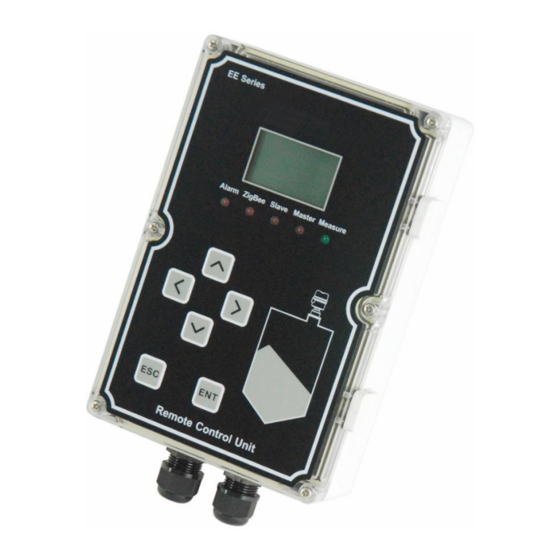
3.4 Product Testing & Protection Protection Level: IP65 (IEC60529) High Voltage Test: IEC60947-2 Insulation Resistance Test: IEC60092-504 Power Supply Test: IEC60092-504 Power Supply Failure Test: IEC60092-504 3.5 Structure RCU Structure Overview... -
Page 9: Specification
4. SPECIFICATION 4.1Technical Specifications ITEM DESCRIPTION POWER SUPPLY DC/AC 20V~250V MAXIMUM 200mA~250mA( Condition:contect 128 sensor ) CURRENT AMBIENT -40℃ - 85℃ TEMPERATURE OPERATION -40℃ - 85℃ TEMPERATURE PROTECTION IP65 STANDARD BODY MATERIAL DISPLAY LCM 128*64 dots Graphic Display SPDT 3A/250V X 1 RELAY OUTPUT (Sensor_alarm*1 (Sending an alarm signal) 1、RS-485(Master) -
Page 10: Ordering Information
4.5 Alarm Alert Description The relay will detect the abnormal status of all sensors connected to the RCU. The abnormal status is defined by the sensor. For example, when the hammer is connected, it will detect any abnormal status during embedding, disconnection, feed protection etc. -
Page 11: Dimension
4.6 DIMENSION BODY COVER... -
Page 12: Product Inspection
5. PRODUCT INSPECTION 5.1 Opening the box Before opening the package, please check that the outer packaging is not deformed or damaged. If there are any package deformities or damage, please take photos or videos as evidence during submission of claims. ... -
Page 13: Installation Instructions
6. INSTALLATION INSTRUCTIONS 6.1 Installation Location 6.1.1 Choose a location where sunlight will not directly fall on the RCU as it may result in user being unable to read the LCD panel clearly. shelter or concrete wall 6.1.2 A proper shelter from rain is needed. Continuous corrosion from rain will cause deterioration and permeation of water. -
Page 14: Precautions
Avoid opening the cover unless there is an emergency. 6.4 Wiring Up & Display Instructions 6.4.1 System Flowchart The RCU is equipped with three RS-485 terminals and one relay output terminal. Usage and definitions are as follows: Power Input: 20~250Vdc/Vac ... - Page 15 RS485 RS-485轉 to RS232 RS-232 Sensor Alarm converter S485- Sensor error Commulication Disconnect COM1 M485+ M485- Rcu電路板 Circuit board M485+ 20~250VAC M485- 20~250VDC 6.4.3 Description and Precautions Terminal no. Item Description S485 RS-485 terminal for the PC (S485+ S485-) 3.4.5.6...
-
Page 16: Operation
7. OPERATION 7.1 RCU Flowchart (Parameters) -
Page 17: Panel Function Description And Flowchart (Single Data Mode)
Shows all the connected 所有ALARM狀態 Sensor alarm state. 進入RCU設定參數 Into RCU’s parameter 的密碼頁面 Password page. Below -- SENSOR Verify the implementipon 顯示下一SENSOR Sensor is connected into 確認是否執行掃瞄頁面 To scan the sensor page. 進入RCU所連接的SENSOR the RCU to set parameter Password page. 設定參數密碼頁面... - Page 18 ID of sensor Display Value Current value of sensor Prompts when sensor sends an alarm signal。 Alarm The measuring unit used by RCU (in both display & setting). Two types of measuring Display Unit units: meter or feet Alarm Alarm signal detected...
-
Page 19: Panel Function Description And Process (4 Data Mode)
Alarm ZigBee Slave Master Measure ITEM DESCRIPTION Supplier Finetek Co Ltd Alarm Signal Displayed while the sensor sends an alarm signal Sensor ID ID of sensor currently being displayed. Value & Unit The value and unit of current sensor. Measurement... -
Page 20: Rcu Parameter-Changing Flowchart
YES>> The RCU now is refreshing hardware. Parameters under UUC will be cleared. NO>> Get to the next page Remark: The RCU will directly jump to the next page provided that there is no action for 10 seconds Click to get... - Page 21 Format: One datum/ one Scan Number to the sensor: 20 page Unit: Meter BaudRate to the PC: 9600 LCM backlight: 120 SEC RCU ID for PC: 001 Language: English Format for PC: RTU ROI:Cleared Move the cursor by using . Click to get to the next page.
- Page 22 (1)CONNECT DEVICE) To do the communication settings between the RCU and the sensors connected. The RCU serves as a Master here. (2)PC(CONNECT PC) To do the communication settings between the RCU and the PC. The RCU serves as a Slave here.
- Page 23 (2-1-1)INTERFACE) Choose INTERFACE and click to do the settings. to choose the interface, and click to confirm. Click to get back to the last page without saving. Remark: default RS-485 (2-1-2)BAUDRATE) Choose BAUDRATE and click to do the settings. to choose, and then click to save.
- Page 24 Below are the various parameter setting options: (1)ADDRESS To set up the ID of the RCU itself for the PC to read data. (2)BAUDRATE BaudRate to the PC. (3)FORMAT Format of the connection to the PC.
- Page 25 (2-2-1)ADDRESS Choose ADDRESS and then click to do the settings. to move onto the digit that is to be adjusted. Use to increase or decrease the digits, ranged from 1~255. Click to confirm; click to get back to the last page without saving. Remark: default 001 (2-2-2)BAUDRATE Choose BAUDRATE and click to do the settings.
- Page 26 (2-2-3)FORMAT Choose FORMAT and then click to do the settings. to choose the preferred format, and click to confirm. Click to get back to the last page without saving. Remark: Default RTU (For PC) (3)MAIN DIS MODE Choose MAIN DIS MODE and click to do the settings.
- Page 27 (3-1) DISPLAY RATE Choose DISPLAY RATE and click to do the settings. to choose the preferred option, and click to confirm. Click to get back to the last page without saving. Remark: default 6 seconds (3-3)DISPLAY UNIT Choose DISPLAY FORMAT and click to do the settings.
- Page 28 Choose PASSWORD CHANGE and click to do the settings. The PASSWORD CHANGE page provides the following setting options (1) RCU PASSWORD To get the access to the RCU parameters. (2) USER PASSWORD To get the access to the sensor parameters.
- Page 29 Remark: Default2123 # After changing the RCU password, please remember the password to avoid losing access to the RCU parameter setting. (4-2) USER PASSWORD Choose the USER PASSWORD and click to do the settings.
- Page 30 (5)LANGUAGE) Select (LANGUAGE) by pressing key on the settings page. You can use button to select the desired system language. Press to save the setting. Press to save the setting. Press ESC to return to the previous page without changing the setting. The default language is English. (6) DEFAULT Choose DEFAULT and click to do the settings.
-
Page 31: Roi Region Of Interest
7.5 ROI Region of Interest 7.6 ROI Region of Interest Click while in the main page to enter Click to set up ROI or clear ROI. Click t o confirm or click to get back to the last page. - Page 32 (1) New ROI On the ROI settings page, select Add ROI and click to enter. Click to choose the ID region (Region) you want to set. In principle, adding ROI starts from the first group, and the system can set 10 groups. Press to show the ID settings.
-
Page 33: Modbus Address Table
7.7 ModBus address table (ex : 10 DEVICE by AUTO ID) Address Variable Remark Item 0x1000 Company Code 1 auto_id 'FI' 0x1001 Company Code 2 'NE' 0x1002 Company Code 3 '-T' 0x1003 Company Code 4 'EK' 0x1004 Product type stc_pfc_auto_id 0x1005 Product No. - Page 34 DEVICE_1(AUTO ID) DEVICE_2(AUTO ID) 0x1020 device_1 Company Code 1 'FI' 4161 0x1040 device_2 Company Code 1 'FI' 0x1021 device_1 Company Code 2 'NE' 4162 0x1041 device_2 Company Code 2 'NE' 0x1022 device_1 Company Code 3 '-T' 4163 0x1042 device_2 Company Code 3 '-T' 0x1023 device_1 Company Code 4...
- Page 35 DEVICE_3(AUTO ID) DEVICE_4(AUTO ID) 'FI' 0x1060 device_3 Company Code 1 'FI' 4225 0x1080 device_4 Company Code 1 'NE' 0x1061 device_3 Company Code 2 'NE' 4226 0x1081 device_4 Company Code 2 '-T' 0x1062 device_3 Company Code 3 '-T' 4227 0x1082 device_4 Company Code 3 'EK' 0x1063 device_3 Company Code 4...
- Page 36 DEVICE_5(AUTO ID) DEVICE_6(AUTO ID) 0x1100 device_5 Company Code 1 'FI' 0x1120 device_6 Company Code 1 'FI' 0x1101 device_5 Company Code 2 'NE' 0x1121 device_6 Company Code 2 'NE' 0x1102 device_5 Company Code 3 '-T' 0x1122 device_6 Company Code 3 '-T' 0x1103 device_5 Company Code 4 'EK'...
- Page 37 DEVICE_7(AUTO ID) DEVICE_8(AUTO ID) 0x1140 device_7 Company Code 1 'FI' 0x1160 device_8 Company Code 1 'FI' 0x1141 device_7 Company Code 2 'NE' R 0x1161 device_8 Company Code 2 'NE' 0x1142 device_7 Company Code 3 '-T' 0x1162 device_8 Company Code 3 '-T' 0x1143 device_7 Company Code 4...
- Page 38 DEVICE_9(AUTO ID) DEVICE_10(AUTO ID) 0x1180 device_9 Company Code 1 'FI' 4417 0x1200 device_10 Company Code 1 'FI' 0x1181 device_9 Company Code 2 'NE' 4418 0x1201 device_10 Company Code 2 'NE' 0x1182 device_9 Company Code 3 '-T' 4419 0x1202 device_10 Company Code 3 '-T' 0x1183 device_9 Company Code 4...
-
Page 39: Rcu Connection Diagram
7.8 RCU Connection Diagram RS-485轉 RS-485 to RS-232 RS-232 converter RS-485 ModBus Slave RS-485 ModBus Master... -
Page 40: How To Set Up
The existing ROI parameter settings will also be cleared. The default number of devices that RCU will scan is 128 units. If the actual number of connections of IDs is not 128, please change the setting for number of scans to the appropriate number. - Page 41 Setting Up 2 Back to main menu page Back to the main page and proceed with the following steps: Start to set up the 8013 parameters, each setting is for ID 5-10, 21-23, 26-30 Setting Up 3 Back to main menu page Operate the Modbus Poll at the PC for connection.
-
Page 42: Maintenance
8. Maintenance 8.1 Daily Maintenance 8.1.1 A regular check on the structure is necessary. Make sure each component is firmly fixed, especially when the RCU is used in humid, dusty facilities. 9. Troubleshoot Possible Failure Trouble Inspection Solution Cause Wiring failure or no...
Need help?
Do you have a question about the RCU and is the answer not in the manual?
Questions and answers