
Related Manuals for Cormach SUPER VIGOR 2450


Summary of Contents for Cormach SUPER VIGOR 2450
- Page 1 SMONTAGOMME TYRE CHANGER SUPER VIGOR 2450 02/2010 MANUALE USO E MANUTENZIONE USE AND MAINTENANCE MANUAL...
- Page 2 ...
-
Page 3: Table Of Contents
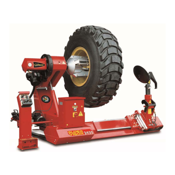
ISTRUZIONI ORIGINALI TRANSLATION OF ORIGINAL INSTRUCTIONS INDICE CONTENTS DESTINAZIONE D’USO INTENDED USE NORME GENERALI DI SICUREZZA GENERAL SAFETY RULES TRASPORTO TRANSPORT DISIMBALLO UNPACKING INSTALLAZIONE INSTALLATION MONTAGGIO E MESSA IN SERVIZIO ASSEMBLY AND COMMISSIONING ACCANTONAMENTO LAY-OFFS ROTTAMAZIONE SCRAPPING DATI TECNICI TECHNICAL DATA 10 CARATTERISTICHE D’IMPIEGO 10 SERVICE CHARACTERISTICS 11 DATI DI TARGA... - Page 4 1 Interruttore generale 1 Master switch 2 Mandrino 2 Turntable 3 Utensile 3 Tool 4 Carrello porta utensile 4 Tool-holder carriage 5 Disco stallonatore 5 Bead breaker disk 6 Braccio porta utensile 6 Tool-holder arm 7 Leva alzatalloni 7 Bead lifting lever 8 Manipolatore 8 Control lever...
- Page 5 Dimensioni d’ingombro Overall dimensions...
-
Page 6: Destinazione D'uso
CONSULTAZIONE DA PARTE DEGLI OPERATORI. TION BY THE OPERATORS. Lo smontagomme Mod. SUPER VIGOR 2450 è stato The Mod. SUPER VIGOR 2450 tyre changer is con- realizzato per essere utilizzato nello smontaggio e structed for use to remove the tyres of trucks, agricultural montaggio di pneumatici d’autocarri, trattori agricoli e... -
Page 7: Norme Generali Di Sicurezza
2 NORME GENERALI DI SICUREZZA 2 GENERAL SAFETY RULES L’uso dell’apparecchiatura è consentito solo a personale The machine must only be used by specially trained and speciically authorised personnel. Any tampering with appositamente addestrato e autorizzato. Ogni e qual- siasi manomissione o modiica dell’apparecchiatura non or modiication to the equipment not authorised by the preventivamente autorizzate dal costruttore sollevano manufacturer in advance relieves the manufacturer of... -
Page 8: Trasporto
3 TRASPORTO 3 TRANSPORT Tutti i movimenti della macchina ancora imballata devo- While the machine is still in its packaging, it may only be no essere effettuati tramite un transpallet o un carrello handled using a pallet truck or a fork-lift truck, inserting elevatore, inforcando le pale di questi nelle apposite the forks in the slots provided underneath the packag- feritoie poste sotto all’imballo o alla cassa. -
Page 9: Disimballo
ATTENZIONE CAUTION Per evitare danneggiamenti non sovrapporre altri To avoid damage, never place other items on top of colli sull’imballo. the packaging. E’ assolutamente vietato utilizzare appigli Gripping the various projecting parts of impropri sui vari organi sporgenti della the structure in a manner not recommen- struttura. -
Page 10: Installazione
5 INSTALLAZIONE 5 INSTALLATION ATTENZIONE CAUTION Al momento della scelta del luogo di installazione When choosing the installation site, comply with the è necessario osservare le normative in uso della current regulations as regards safety at work. Each machine must be installed on a stable, rigid loor. sicurezza sul lavoro. -
Page 11: Montaggio E Messa In Servizio
6 MONTAGGIO E MESSA IN SERVIZIO 6 ASSEMBLY AND COMMISSIONING Dopo aver liberato i vari componenti dall’imballaggio After unpacking the various components and checking e aver controllato lo stato di integrità e la mancanza di them for damage or any anomalies, follow the instructions eventuali anomalie, seguire le seguenti istruzioni per provided below to assemble the various components. -
Page 12: Accantonamento
7 ACCANTONAMENTO 7 LAY-OFFS In caso di accantonamento per un lungo periodo è ne- If the machine is to be out of use for a long period, cessario scollegare le fonti di alimentazione, svuotare disconnect it from the power sources, empty the tank containing the hydraulic luid, and protect those parts il serbatoio contenente il liquido di funzionamento, e provvedere alla protezione di quelle parti che potreb-... -
Page 13: Technical Data
Hydraulic luid: irst-aid guidance. Olio: indicazioni di pronto soccorso. Ingestione: non è necessario nessun trattamento di Swallowing: no treatment is needed. cura. Aspiration of liquid: in case of spontaneous vomiting, Aspirazione di liquido: in caso di vomito spontaneo, take the affected person to hospital urgently. trasportare il colpito d’urgenza all’ospedale. -
Page 14: Nameplate Data
- Phone 0039-0522-631274 - fax 0039-0522-631284 - marchio CE - CE mark - anno di costruzione : - year of construction: - modello: SUPER VIGOR 2450 - model: SUPER VIGOR 2450 12 MANUTENZIONE ORDINARIA 12 ROUTINE MAINTENANCE Per garantire l’eficienza dell’apparecchio, e per il suo To guarantee the machineís eficiency and correct op-... -
Page 15: Troubleshooting Table
13 TABELLA DI RICERCA EVENTUALI GUASTI INCONVENIENTE POSSIBILE CAUSA RIMEDIO 1 Controllare i ili 1 Filo di linea a massa Muovendo i manipolatori i fu- 2 Invertitore in corto 2 Sostituire invertitore sibili saltano 3 Motore in corto 3 Sostituire il motore 1 Tubo idraulico pompa in granaggi 1 Sostituire tubo Il cilindro stallonatore ha poca... -
Page 16: Instructions For Use
14 INSTRUCTIONS FOR USE ATTENZIONE CAUTION Il modello SUPER VIGOR 2450 deve essere utilizzato The SUPER VIGOR 2450 model must only be used solo da personale autorizzato. Si ricorda che even- by authorised personnel. tuali utilizzi da parte di persone non a conoscenza... - Page 17 FUNZIONE DEI 3 LED VISIBILI SULLA SCATOLA FUNCTIONS OF THE 3 LEDS ON THE CONTROL DEL MANIPOLATORE LEVER BOX FUNZIONAMENTO DEL MANIPOLATORE CON CONTROL LEVER BOX OPERATION IN CABLE CAVO MODE Come aiuto visivo per l’utilizzatore, sul manipolatore è As a visual aid to the user, the control lever box has a presente un led di colore verde che realizza il monito- green LED which monitors the system which transmits raggio del sistema di trasmissione dei comandi impartiti...
- Page 18 Quando questo led bianco è spento non è impossibile MACHINE OPERATION IN RADIO MODE (optional) inviare comandi alla macchina dal manipolatore. RECEPTION MONITORING VIA EXTERNAL LED FUNZIONAMENTO DELLA MACCHINA CON RADIO (optional) As a visual aid to the user, the door of the electrical cabinet mounts a white LED which monitors the radio MONITORAGGIO DELLA RICEZIONE PER MEZZO DI control reception system.
- Page 19 POSIZIONAMENTO / BLOCCAGGIO RUOTA POSITIONING/CLAMPING THE WHEEL - Ribaltare all’indietro il braccio portautensile - Tip the tool-holder arm back - Sistemare la ruota in posizione verticale sul pianale - Place the wheel vertical on the machine bed della macchina - Operate the turntable to load and clamp the wheel - Azionare l’autocentrante in modo opportuno per il caricamento e bloccaggi della ruota ATTENZIONE...
- Page 20 ROTAZIONE UTENSILE E DISCO STALLONATORE ROTATING THE TOOL AND BEAD BREAKER DISK (Fig. 5-6) (Fig. 5-6) Per passare dall’utilizzo dell’utensile (A) al disco stallo- To pass from use of the tool (A) to use of the bead natore (B) ruotare il gruppo di 180°, ribaltare il gruppo breaker disk (B), turn the assembly through 180°...
- Page 21 Far salire la ruota in corrispondenza della rampa di Raise the wheel to the ascent ramp using the control lever salita, agendo sul manipolatore (3 Fig. 4), avvicinare il (3, Fig. 4), and move the turntable towards the wheel. mandrino alla ruota. Posizionare il mandrino coassiale Position the turntable on the same axis as the centre of con il centro della ruota in modo da poter bloccare il the wheel, so that the rim can be blocked on the inside...
- Page 22 SMONTAGGIO E MONTAGGIO RUOTE TUBELESS REMOVING AND FITTING TUBELESS TYRES Dopo aver bloccato la ruota sul mandrino agendo sui After clamping the wheel on the turntable using the comandi (4 Fig. 4) alzare la ruota agendo sui comandi controls (4 Fig. 4), raise the wheel using the controls (3 Fig.
- Page 23 Per il montaggio del pneumatico issare il morsetto sul To it the tyre, ix the clamp on the edge of the rim in the bordo del cerchio nella posizione alta, appoggiarvi so- high position, place the two beads on it and operate the pra i due talloni, con il disco agire contro il pneumatico disk against the tyre (after lubricating the beads and the (dopo aver lubriicato i talloni e il bordo del cerchio)
- Page 24 Per lo smontaggio del secondo bordo, portare il braccio To remove the second edge, bring the tool-holder arm utensile dalla parte interna della ruota girando l’utensile to the inside of the wheel, turning the tool, and insert it e inserendolo tra il tallone e il cerchio, si ripete l’opera- between the bead and the rim, then repeat the previous zione precedente di smontaggio (Fig.
- Page 25 SMONTAGGIO RUOTE A CERCHIETTO REMOVING TYRES FROM WHEELS WITH SPLIT RING Posizionare il disco stallonatore a ilo del cerchio dalla Place the bead breaker disk against the rim from the parte esterna, far ruotare il mandrino e avanzare contem- outside, rotate the turntable and at the same time move poraneamente li carrello da destra verso sinistra in modo the carriage from right to left so that the tyre is pushed da spingere verso l’interno il pneumatico (Fig.
- Page 26 MONTAGGIO RUOTE A CERCHIETTO FITTING TYRES ON WHEELS WITH SPLIT RING Dopo aver lubriicato con l’apposito grasso la supericie After lubricating the surface of the rim and the tyre beads with the special grease, it the tyre complete with inner del cerchio e i talloni del pneumatico introdurre il pneu- matico completo di camera d’aria e laps nel cerchio, tube and laps onto the wheel.
-
Page 27: Fire-Fighting Equipment
15 MEZZI ANTINCENDIO DA UTILIZZARE 15 FIRE-FIGHTING EQUIPMENT La macchina è formata da parti molto diverse tra loro, per The machine consists of a variety of very different parts, so the measures to be taken in case of ire must also questo motivo anche le misure antincendio da adottare dovranno essere diverse. - Page 28 dere gratuitamente un altro apparecchio a ine vita a A disposal of the product different from what described condizione che sia di tipo equivalente ed abbia svolto above will be liable to the penalties prescribed by the le stesse funzioni del prodotto acquistato. national provisions in the country where the product is disposed of.
-
Page 29: Extraordinary Maintenance
16 MANUTENZIONE STRAORDINARIA (per soli 16 EXTRAORDINARY MAINTENANCE (for REPAIR TECNICI RIPARATORI) ENGINEERS only) a) After the irst few working hours, check and tighten a) Dopo le prime ore di lavoro controllare e serrare (se è necessario), raccorderia e bulloneria secondo le coppie unions, bolts and nuts (if necessary) using the driving di serraggio come indicato in tabella torques stated in the table. - Page 30 CAP. 17 SCHEMA ELETTRICO CHAP. 17 ELECTRIC WIRING SUPER VIGOR 2450 CHAP. 17 SCHEMA ELECTRIQUE KAP. 17 ELEKTRISCHER SCHALTPLAN CAP. 17 ESQUEMA ELECTRICO 00027963...
- Page 31 CAP. 17 SCHEMA ELETTRICO CHAP. 17 ELECTRIC WIRING SUPER VIGOR 2450 CHAP. 17 SCHEMA ELECTRIQUE KAP. 17 ELEKTRISCHER SCHALTPLAN CAP. 17 ESQUEMA ELECTRICO SCHEDA EPPB EPPB CIRCUIT BOARD SCHEDA HTCCB HTCCB CIRCUIT BOARD RADIO MODEM Radio modem FUSIBILI FUSES FUSIBILI...
- Page 32 CONNECTOR POLARISATION CARRIAGE CARRIAGE TURNTABLE TURNTABLE TURNTABLE TURNTABLE TOOL CLOCKWISE ANTICLOCKWISE TOOL TRAVEL TRAVEL OPENING CLOSING ROTATION ROTATION ROTATION RAISE/LOWER SECOND SPEED NOTE: Pin 1 of SA1 must point upwards. VERSION VERSION ONLY ONLY...
- Page 33 CAP. 17 SCHEMA ELETTRICO CHAP. 17 ELECTRIC WIRING SUPER VIGOR 2450 CHAP. 17 SCHEMA ELECTRIQUE KAP. 17 ELEKTRISCHER SCHALTPLAN CAP. 17 ESQUEMA ELECTRICO SCHEDA SPMI-24C SPMI-24C CIRCUIT BOARD RADIO MODEM RADIO MODEM GB1 BATTERIA GB1 BATTERY SA1 COMANDO TRASLAZIONE CARRO...
- Page 34 Cap. 17 SCHEMA IDRAULICO Chap. 17 HYDRAULIC DIAGRAM SUPER VIGOR 2450 Chap. 17 SCHEMA HYDRAULIQUE Kap. 17 HYDRAULIKSCHALTPLAN Cap. 17 ESQUEMA HIDRAULICO 00018998...
- Page 35 Cap. 17 SCHEMA IDRAULICO Chap. 17 HYDRAULIC DIAGRAM SUPER VIGOR 2450 Chap. 17 SCHEMA HYDRAULIQUE Kap. 17 HYDRAULIKSCHALTPLAN Cap. 17 ESQUEMA HIDRAULICO SERBATOIO TANK FILTRO FILTER POMPA PUMP GIUNTO COUPLING MOTORE ELETTRICO ELECTRIC MOTOR VALVOLA DI MASSIMA RELIEF VALVE ELETTROVALVOLA TRASLAZIONE CARRELLO...
- Page 36 Cap. 17 SCHEMA COLLEGAMENTO TUBAZIONI IDRAULICHE Chap. 17 HYDRAULIC PIPING CONNECTION DIAGRAM SUPER VIGOR 2450 Chap. 17 SCHEMA RACCORDEMENT TUYAUTERIES HYD. Kap. 17 ANSCHLUSSPLAN HYDRAULISCHE LEITUNGEN Cap. 17 ESQUEMA DE CONEXIONES TUBERIA HID. DENOMINAZIONE LUNGHEZZA CODICE TUBO FLEX 3/16” L=1800...
- Page 38 CORMACH S.r.l. via A. Pignedoli, 2 42015 CORREGGIO (RE) ITALY Tel. +39 0522 631274 - Fax +39 0522 631284 e-mail: cormach@cormachsrl.com www.cormachsrl.com ...
Need help?
Do you have a question about the SUPER VIGOR 2450 and is the answer not in the manual?
Questions and answers