Advertisement
Quick Links
Advertisement

Summary of Contents for ABS Provides
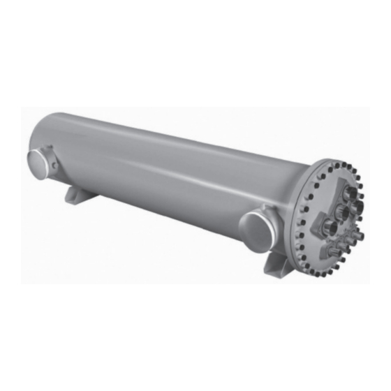
- Page 1 Operating Instructions Flooded Heat Exchangers...
-
Page 2: Our Products
OUR PRODUCTS... - Page 3 Index INDEX Declaration of conformity to ASME Preliminary remarks Introduction Material inspection Handling and transportation Storage Installation Set-up Start-up and utilization Maintenance and controls by the user Safety Disposal Warranty Appendix...
- Page 4 1. Declaration of conformity to ASME DECLARATION OF CONFORMITY TO ASME ALL PRESSURE VESSELS MANUFACTURED BY PROVIDES US, INC. MEET ALL OF THE REQUIREMENTS OF ASME BOILER AND PRESSURE VESSEL CODE. THE DATA PLATE ON EACH VESSEL WILL BE MARKED WITH THE APPROPRIATE CODE MARKINGS AND REQUIRED INFORMATION.
-
Page 5: Preliminary Remarks
• inadequate utilization of the pressure equipment • modifcations to or tampering with the pressure equipment • modifcations to the pressure equipment issued by personnel not authorized by Provides US, Inc. • non-observance of what is written in this Operating Instruction manual... - Page 6 INTRODUCTION 3.1 FLOODED EVAPORATOR The main application of PROVIDES flooded heat exchangers (from here simply “Flooded EV”) is into HVAC plants, in which through the thermal cycle of condensation and evaporation of the refrigerant, intended as the primary fluid, transfers heat to the secondary fluid (generally water) condensing or evaporating itself.
-
Page 7: Material Inspection
4. Material inspection MATERIAL INSPECTION Before undergoing any operation on the heat exchanger make sure that the delivered equipment is what you have ordered, verifying the correctness of the nameplate. The general nameplate is located onto the shell and it is possible to read the model of the heat exchanger, the serial number, the year of construction, the design and test temperatures and pressures, the volumes and the fluid types. -
Page 8: Handling And Transportation
5. Handling and transportation HANDLING AND TRANSPORTATION PROVIDES heat exchangers are internally charged with nitrogen so as to guarantee their perfect conservation, also in corrosive environments. In case of sea freight the heat exchangers are individually wrapped. On request it is possible to supply heat exchangers in wooden cases in compliance with the enforced norms of the delivering country. - Page 9 (water and refrigerant). 6.1 Rust prevention PROVIDES heat exchangers’ external surface is protected by a rustproof primer and by a final color coat. On request it is possible to supply adhesive insulation that covers the whole surface of the evaporator.
-
Page 10: Installation
The correct installation of refrigerant and water connections is described in the following figures. 7.1.1 Refrigerant side PROVIDES Flooded EV can have 1 to “n” refrigerant circuits. The standard layout of 1 circuit flooded consists in one gas outlet on the top of the shell, one liquid inlet on the bottom of the shell and a series of welded fittings for safety and service accessories. - Page 11 7. Installation The standard layout of “n” circuits flooded evaporator consists in “n” refrigerant chambers, each provided with a series of welded fittings for safety and service accessories. 2 CIRCUITS (DUAL) – EVAPORATOR MODEL The connections can be positioned according to client request and constructive feasibility. Refrigerant connections may be different, depending on the model of flooded and will be mounted with bolted flanges.
- Page 12 The correct installation of refrigerant and water connections is described in the following figures. 7.2.1 Refrigerant side PROVIDES condensers can have 1 or “n” refrigerant circuits. The standard layout of 1 circuit condensers consists in one gas inlet on the top of the shell, one liquid outlet on the bottom of the shell and a series of welded fittings to be used for safety accessories, pressure gauges and cocks.
- Page 13 7. Installation The standard layout of “n” circuits condensers consists in “n” independent refrigerant side circuits, each equipped with refrigerant inlets and outlets and a series of welded connections. 2 CIRCUITS (DUAL) GAS INLET GAS INLET FITTINGS FOR ACCESSORIES FITTINGS FOR ACCESSORIES LIQUID OUTLET LIQUID OUTLET Refrigerant connections may be placed in different positions (longitudinally) depending on the Client request...
- Page 14 7. Installation 7.2.2 Water Side Water side of condensers can vary from 1 up to 4 passes, on tube bundle condensers, while “n” circuits in the case of compact condensers. The headers can be in cast or iron or carbon steel. On 1 Pass models the inlet connection is placed on one header and the outlet is on the opposite header.
- Page 15 7. Installation On models with both condensing and heat recovery circuits, (1 Pass + 2 Passes) the inlet connection of the heat recovery circuit is on the same side of the inlet connection of the condensing circuit (the last one is placed in the lower side of the header), while the outlet connection of the heat recovery circuit is placed on the opposite header of the condenser.
- Page 16 7. Installation Victaulic® kits (see appendix fig. 14.2) Victaulic® kits consist of 2 coupling connections supplied with EPDM gaskets on the inside and 2 connection pipes. For the installation of the kit follow the steps below: • loosen the coupling connection and extract the gasket. •...
- Page 17 7. Installation 7.7 Warnings • Do not expose the heat exchanger to localized loadings due to supports (different from the mounting lugs), stiffening and connection pipes. • Do not expose the heat exchanger to dynamic and/or localized loads; dynamic overpressures and water head could damage it.
- Page 18 START-UP AND UTILIZATION In the case of SILICONE FREE units, PROVIDES declares that to the best of it’s knowledge and based on previous findings and information available from it’s suppliers at the time of the request, that the heat exchanger does not intentionally contain silicone, although there might be traces due to impurities in the raw materials.
- Page 19 10. Maintenance and controls by the user MAINTENANCE AND CONTROLS BY THE USER DO NOT REMOVE REFRIGERANT FROM PRIMARY CIRCUIT WITHOUT HAVING A FLOW IN THE SECONDARY CIRCUIT - IF THIS IS NOT POSSIBLE MAKE SURE THAT THE SECONDARY CIRCUIT IS COMPLETELY EMPTY TO AVOID FREEZING. DO NOT OPEN THE HEAT EXCHANGER UNDER PRESSURE Use, when necessary, inhibited brine antifreeze solutions and verify them periodically, avoiding their contact with air.
- Page 20 10. Maintenance and controls by the user • Always install a filter in the water inlet circuit, in order to reduce the entry of solid particles; • Drain totally the vessel before doing any maintenance operations; • Do not clean the flooded with non-suitable mechanical systems, e.g. drills or too high pressure jets; •...
- Page 21 10. Maintenance and controls by the user RECOMMENDATION FOR THE SUSTAINABILITY OF COPPER AND CuNi TUBES WITHIN WATER CONTENT SUBSTANCES CONCENTRATION COPPER CuNi [-] o [mg/l] < 6 pH-Value 6 - 8 > 8 < 10 10 - 100 Chloride (CI-) 100 - 1000 >...
- Page 22 10. Maintenance and controls by the user 10.2 Header assembly and gasket replacement Proceed as follow in order to disassemble the header: • Remove pipeline; • Always be sure to totally drain the water before removing the header; • Remove insulation from the front side of the heat exchanger (if present); •...
- Page 23 10. Maintenance and controls by the user FIG. 10.2.1 FIG. 10.2.2 TORQUE FOR BOLTS 20 Nm / 14.8 ft. lbf. 35 Nm / 25.8 ft. lbf. 80 Nm / 59 ft. lbf. 140 Nm / 103.3 ft. lbf. 180 Nm / 132.8 ft. lbf. 200 Nm / 147.5 ft.
- Page 24 10. Maintenance and controls by the user 10.3 Summary of periodical checks The following is a list of recommended maintenance and inspections and their frequency. FREQUENCY FLOODED PERIODICAL IF NECESSARY Check the effective working conditions in compliance Every 3 years with Producer indications and/or start-up declaration) Check the functioning of safety accessories Every 3 years...
- Page 25 IN CASE OF LEAKAGE, STOP IMMEDIATELY THE OPERATION OF THE PRESSURE EQUIPMENT DISPOSAL This pressure equipment contains recyclable materials (carbon steel, copper, plastics, etc.). At the end of its useful lifetime get information about the laws in force in your country regarding recycling. PROVIDES pressure equipment is supplied with recyclable packaging.
-
Page 26: Warranty
Any eventual anomalies in materials and/or defects in manufacture found during the period of warranty, will engage Provides US, Inc. to repair or, to its judgment, to replace and to test, in the shortest possible time, those parts that are not suitable for the use for which they are designed. - Page 27 The Client shall not sell or market Products not in compliance with the Laws and Regulations mentioned under letter H and I above. In the case of the contrary, the Client shall exclude any liability for Provides US, Inc. for any damage or loss suffered by the latter, due to any third party’s and/or authority’s claim raised as a consequence of the manufacture by Provides US, Inc.
- Page 28 14. Appendix APPENDIX Fig. 14.2 VICTAULIC® CONNECTION BOLTS GASKET COUPLINGS...
- Page 29 14. Appendix...
- Page 32 Provides US Inc. P.O Box 917 45 Sutton Road, Verona, Va. 24482 Tel. 540-569-3434 - Fax 540-466-5831 e-mail: sales@providesus.com - www.providesus.com...
Need help?
Do you have a question about the Provides and is the answer not in the manual?
Questions and answers