Table of Contents

Related Manuals for ProGear 225

Summary of Contents for ProGear 225
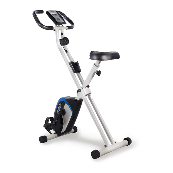
- Page 1 Folding Upright Bike with Pulse IMPORTANT: Read all instructions carefully before using this product. Retain this owner’s manual for future reference. The specifications of this product may vary from this photo, subject to change without notice. 3102.6-020620...
- Page 2 PLEASE DO NOT RETURN THIS PRODUCT TO THE STORE. STOP and contact customer service if you have any questions regarding assembly or proper operation of the machine Email us at: Service@paradigmhw.com Or call us at: 1-844-641-7920 Hours: 8:00 am to 5:00 pm (PST) Monday thru Friday...
-
Page 3: Table Of Contents
TABLE OF CONTENT SERVICE -------------------------------------------------------------------------- 2 LABEL PLACEMENT ---------------------------------------------------------- 3 PRODUCT SAFETY------------------------------------------------------------ 4 OVERVIEW DRAWING ------------------------------------------------------- 6 PARTS LIST ---------------------------------------------------------------------- 7 HARDWARE & TOOLS Pack ------------------------------------------------ 9 ASSEMBLY ----------------------------------------------------------------------- 10 COMPUTER ---------------------------------------------------------------------- 16 STORAGE ------------------------------------------------------------------------ 17 ADJUSTMENTS ----------------------------------------------------------------- 18 TRANSPORTING THE BIKE ------------------------------------------------ 20 TROUBLE SHOOTING &... -
Page 4: Service
SERVICE IMPORTANT: FOR NORTH AMERICA ONLY For damaged or defective product, questions, replacement parts or any other service support, please contact our customer service department (8:00 AM - 5:00 PM Pacific Standard Time, Monday thru Friday) by the below methods: For The Best Service, please Email: service@paradigmhw.com Response Time: 1-2 Business Days... -
Page 5: Label Placement
LABEL PLACEMENT... -
Page 6: Product Safety
PRODUCT SAFETY Basic precautions should always be followed, including the following safety guidelines when using this equipment. Read all of the guidelines before using this equipment. Before exercising and to avoid injuring your muscles, it is highly recommended that you perform warm-up exercises for each muscle group. - Page 7 PRODUCT SAFETY WARNING: Before using this equipment you should consult with your personal physician to see if the product is appropriate for you. Do not use this equipment without your physician’s approval. Do not use this equipment if you have any of the following conditions or ailments: ...
-
Page 8: Overview Drawing
OVERVIEW DRAWING... -
Page 9: Parts List
PARTS LIST No. Description No. Description Front Frame 29 Curved Washer Ø8xØ20x1.5t 30 Flat Washer Φ8×25×2.0t Rear Frame 31 Flat Washer Φ18×5×1.5t Seat Post Handlebar 32 Screw M5x20 Front Stabilizer 33 Hexagon Socket Bolt M8×15 34 Flat Washer Φ8×16×1.5t Rear Stabilizer Magnet Bracket 35 Nut M8 36 Axle Φ16×95... - Page 10 PARTS LIST No. Description No. Description 54 Crank Plug Ø63 67 Crank Cover 55 Adjustment Knob M16 68 Bearing Bracket 56 Seat Cushion 69 Belt Wheel with Crank Axle 57 Seat Post Plastic Bushing 70 Computer 58 Rear Stabilizer End Cap 71 Sensor with Wire 59 Front Stabilizer End Cap 72 Sensor Magnet...
-
Page 11: Hardware & Tools Pack
HARDWARE LIST & TOOLS... -
Page 12: Assembly
ASSEMBLY Step 1 1A. Remove the Safety Pin (49) from the Rear Frame (2). Stand up the base of the Rear & Front Frames (2, 1) by pulling them apart from each other. Align the upper pin holes on both frames and then insert the Safety Pin (49) into the uppers holes of the frames to lock the frames in place. - Page 13 ASSEMBLY Tool: 13-19mm Wrench 1PC Step 2 2A. Remove four Cap Nuts (26), four Spring Washers (28), four Curved Washers (29) from the Front Stabilizer (5) and the Rear Stabilizer (6). 2B. Attach the Front Stabilizer (5) with the transport wheels onto the Front Frame (1) with two Cap Nuts (26), two Spring Washers (28), and two Curved Washers (29).
- Page 14 ASSEMBLY Tool: 13-19mm Wrench 1PC Hardware: (55) Adjustment Knob Step 3 3A. Remove three Flat Washers (34) and Three Nuts (35) from the Seat Cushion (56). 3B. Align the bolt holes on the underside of the Seat Cushion (56) with the holes on top of the Seat Post (3).
- Page 15 ASSEMBLY Tool: 13-19mm Wrench 2PCS Step 4 4A. Remove the Left Nylon Nut (52L) and Right Nylon Nut (52R) from the Left Pedal (64L) and Right Pedal (64R). Attach the Left Pedal Strap (79) onto the Left Pedal (64L) and the Right Pedal Strap (80) onto the Right Pedal (64R).
- Page 16 ASSEMBLY Tool: 5mm Allen Wrench with Phillips Screwdriver Step 5 5A. Attach the Handlebar (4) to the Rear Frame (2) with two Hexagon Socket Bolts (27), two Spring Washers (28) and two Curved Washers (29). Tighten the bolts with the 5mm Allen Wrench with Phillips Screwdriver provided.
- Page 17 ASSEMBLY Tool: 5mm Allen Wrench with Phillips Screwdriver Step 6 6A. Remove two Screws (12) from the back side of the Computer (70). 6B. Attach the Computer (70) to the Handlebar (4) with the two Screws (12) that were previously removed.
-
Page 18: Computer
COMPUTER SPECIFICATIONS: TIME --------------------------------------- 0:00-99:59 MIN: SEC SPEED ------------------------------------ 0.0-99.9 ML/H DISTANCE ------------------------------- 0.00-99.99 ML CALORIE --------------------------------- 0.0-999.9 KCAL ODOMETER ----------------------------- 0.00-999 ML PULSE RATE----------------------------- 40-206 BEATS/MIN 1. Press the MODE button until the “ ”appears above the following: a. -
Page 19: Storage
STORAGE For your convenience, the bike can be folded up for storage. 1. Remove the Safety Pin (49) from the upper pin hole of the bike. 2. Fold the Rear Frame (2) and the Front Frame (1) together until the lower pin holes are aligned. -
Page 20: Adjustments
ADJUSTMENTS Tension Control Knob (62) Adjusting the Tension Control Knob To increase the tension, turn the Tension Control Knob (62) in a clockwise direction. To decrease the tension, turn the Tension Control Knob (62) in a counterclockwise direction. Seat Post (3) Adjustment Knob (55) Adjusting the Seat Height Removed the Adjustment Knob (55) by turning it in a counterclockwise direction until the Seat... - Page 21 ADJUSTMENTS Adjusting the Pedal Strap L mark The Left Pedal Strap (79) with marked with a L on the strap (see Figure 1). Snap the three hole end into the inside edge of the Left Pedal (79). See Fig 2 & 3. Select one of the adjustment holes which allow your foot to be easily removed from the pedal.
-
Page 22: Transporting The Bike
TRANSPORTING THE BIKE Transporting the Bike Standing in front of the bike, hold the Handlebar (4) and tilt the machine towards yourself until the wheels on the Front Stabilizer (59) make contact with the floor. Push or pull the unit to the desired location, then gently lower the Rear Stabilizer (2) back down to the ground. -
Page 23: Trouble Shooting& Maintenance
TROUBLE SHOOTING& MAINTENANCE MAINTENANCE Cleaning The bike can be cleaned with a soft clean damp cloth. Do not use abrasives or solvents on the plastic parts. Wipe your perspiration off the bike after each use. Be careful not to get excessive moisture on the computer display panel as this might cause an electrical hazard or electronics to fail. -
Page 24: Warranty
WARRANTY MANUFACTURER’S LIMITED WARRANTY Paradigm Health & Wellness guarantees to the original purchaser that this product is free from defects in material and workmanship when used for the purpose intended, under the conditions that it has been installed and operated in accordance with Paradigm’s Owner’s Manual. Paradigm’s obligation under this warranty applies to the following: COMPONENT LENGTH OF WARRANTY Structural Frame... -
Page 25: Part Request Form
PARTS REQUEST FORM 5. Date of Purchase Paradigm Health & Wellness, Inc. EMAIL THIS FORM WITH YOUR RECEIPT OF PURCHASE TO Service@paradigmhw.com NAME:_____________________________________________________________________________________ ADDRESS:__________________________________________________________________________________ CITY:________________________ STATE:_____________ ZIP:_______________________________________ TELEPHONE: (Day)__________________________________________________________________________ (Night)________________________________________________________________________ SERIAL#:___________________________________________________________________________________ MODEL#:___________________________________________________________________________________ PURCHASE DATE:___________________________________________________________________________ PLACE OF PURCHASE:_______________________________________________________________________ PART # DESCRIPTION “YOUR ORDER WILL BE PROCESSED WITHIN 3 BUSINESS DAYS”...
Need help?
Do you have a question about the 225 and is the answer not in the manual?
Questions and answers