Table of Contents
Advertisement
INSTALLATION GUIDE
MODELS RS1100/RS1100E, RS114
CONTENTS
System Features.......................................
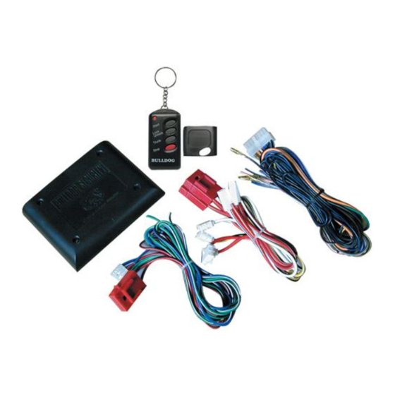
System Components .....................................
Required Tools ........................................
Technical Assistance ..................................
Before You Begin ......................................
Precautions...........................................
Using your Test Probe ................................. 2
Locating & Making Connections........................ 4-6
Neutral Safety Switch ................................. 6
Connecting Wiring Harness ............................. 6
Antenna Placement .....................................
Anti-Theft System .....................................
Optional Features ...................................
Operator Programming Instructions ................... 9-10
How to use Your Remote Transmitter.................. 10-11
All tech personnel are expertly qualified to answer any technical questions.
Technicians are available Monday through Friday from 9:00 a.m. until 8:00 p.m. and Saturday 10:00 a.m. until 4:00 p.m.
OWNER'S GUIDE
REMOTE STARTER
Technical Assistance
Address
288 Canton Avenue • Wintersville, Ohio 43953
Telephone
Phone: 740-264-4710 • 800-878-8007 • Fax: 740-264-7306
•
1
1
1
1
2
2
3
7
7
7-9
Advertisement
Table of Contents

Related Manuals for Bulldog Security RS1100


Summary of Contents for Bulldog Security RS1100
-
Page 1: Table Of Contents
INSTALLATION GUIDE OWNER’S GUIDE MODELS RS1100/RS1100E, RS114 CONTENTS System Features... System Components ... Required Tools ... Technical Assistance ... Before You Begin ... Precautions... Using your Test Probe ... 2 Making Connections ... Locating & Making Connections... 4-6 Neutral Safety Switch ... 6 Connecting Wiring Harness ... -
Page 2: System Features
SYSTEM FEATURES Four-Button Extended Range Remotely start your car to run the heater, air conditioning or defroster from an extended Remote Control distance. Keyless Entry Remotely locks and unlocks your power door locks. Trunk Release/Sliding Door Remotely open your power trunk or your power sliding van door with a push of a button. Remote Programmable Run Time Remotely program your vehicle to run 5 to 15 minutes. -
Page 3: Before You Begin
It is computer controlled and manufactured in the U.S.A. The dependability and variety of features make Bulldog Security the leader in the industry. Enjoy your new remote starter for years to come! This remote system is designed to start your vehicle by sending a command signal from the remote transmitter or by programming automatic temperature start. -
Page 4: Making Wiring Connections
MAKING WIRING CONNECTIONS NOTE: In most cases you should not cut your vehicle wire in two. 1. Strip back two inches of insulation on the wire from the remote starter. 2. Strip back one inch of insulation on the wire you need to connect to. 3. -
Page 5: Locating & Making Connections
2. Twist upper wires together, twist lower wires together as shown. 3. Lay upper twisted pair of wires over right wire as shown. Bring lower twisted pair of wires up to meet the left wire as shown. 4. Use electrical tape to wrap, be sure to cover about 2 inches on either side of connection. Secure with wire ties as shown. - Page 6 1. If your vehicle has only one (1) ignition wire, as most 1993 and older domestic and import vehicles do, connect the heavy gauge WHITE wire to it. 2. If your vehicle has two (2) ignition wires, as most 1994 and newer vehicles do, connect the heavy gauge RED with WHITE stripe wire to the Ignition 2 wire.
-
Page 7: Neutral Safety Switch
PARKING LIGHTS (+12V only with parking lights on) Turn the parking lights to the ON position. (NOT YOUR HEADLAMPS). Probe the wire(s) coming from your headlamp control switch. The correct wire will show +12V and the RED light will glow bright only when the parking lights are ON. Connect the BROWN wire from the 16-pin harness to this wire. -
Page 8: Antenna Placement
ANTENNA PLACEMENT ANTENNA For best results, run the antenna (YELLOW WIRE WITH BLACK TIP from the back of the unit) as high up in the dash and as straight as possible. Do not place the antenna next to any metal parts or the vehicle’s main computer control module. - Page 9 on the switch and test the unlock wire. The correct wire will test (-) negative and the GREEN light will glow bright. Release the unlock button and this wire should again glow both GREEN and RED (dimly). Your vehicle has a “Type B” door locking system. Make sure to mark which wire is lock and unlock.Make sure to mark which wire is lock and unlock.
-
Page 10: Operator Programming Instructions
TRUNK RELEASE AND SLIDING VAN DOOR RELEASE (+) Locate the trunk release or sliding van door release wire coming from the back of the release switch. To determine if your release is tripped by a (+) positive or a (-) negative (most trunk release or van door release switches are (+) positive). -
Page 11: How To Use Your Remote Transmitter
To check programmed runtime, press and release Button #4 (stop), the parking lights will flash for the programmed length of time. Each flash will equal 5 minutes of runtime. Example: Three parking light flashes represents 15 minutes of runtime. RS1100/RS1100E: Starts your vehicle. Locks and unlocks your power door locks.
Need help?
Do you have a question about the RS1100 and is the answer not in the manual?
Questions and answers