Table of Contents
Advertisement
Quick Links
Instruction for user,
Installation &
Servicing
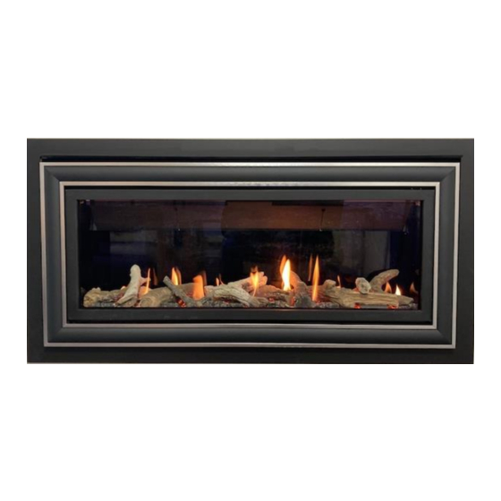
890 HDBF
IMPORTANT
This appliance is guaranteed for 12 months subject to conditions. The 5 year extended parts
warranty will only be valid if the annual service recommended in this manual has been
completed and appliance has been registered online.
Keep this booklet for service log and future reference
Video guides found at http://www.charltonandjenrick.co.uk/infinity-set-up-guides/
Advertisement
Table of Contents

Subscribe to Our Youtube Channel
Summary of Contents for Infinity 890 HDBF
- Page 1 This appliance is guaranteed for 12 months subject to conditions. The 5 year extended parts warranty will only be valid if the annual service recommended in this manual has been completed and appliance has been registered online. Keep this booklet for service log and future reference Video guides found at http://www.charltonandjenrick.co.uk/infinity-set-up-guides/...
-
Page 2: Table Of Contents
Contents EXTENDED FIVE YEAR PARTS WARRANTY ..............................1 Benchmark Scheme ....................................2 Introduction ......................................3 Consumer Protection Information ................................3 Lighting the Appliance & General Operation of Control ........................5 Handset set up video ....................................5 Auto (Thermostatic) Control ..................................7 Menu features...................................... -
Page 3: Benchmark Scheme
Benchmark Scheme Charlton and Jenrick Ltd is a licensed member of the Benchmark Scheme which aims to improve the standards of installation and commissioning of domestic heating and hot water systems in the UK and to encourage regular servicing to optimise safety, efficiency and performance. Benchmark is managed and promoted by the Heating and Hotwater Industry Council. -
Page 4: Introduction
890 HD BF USERS INSTRUCTIONS Introduction The 890 HD BF has been designed and tested to the requirements of EN 613 and is suitable for use in Great Britain. 890 HD BF incorporates a single gas valve which selects ignition pilot, with variable setting between low and high setting and is operated via remote control hand device or optional smart app device. - Page 5 890 HD BF USERS INSTRUCTIONS Important Information The appliance is for use on Natural Gas (G20 @ 20mbar) In Great Britain, the appliance must be installed by a competent person whose name appears on the gas safe register. All Gas Safe engineers should possess an ID carrying the logo below. The glass front of this appliance acts as a dress guard, conforming to BS 1945 (1997) however a fireguard to BS6539 (1997) must be used to protect young children, the elderly or infirm.
-
Page 6: Lighting The Appliance & General Operation Of Control
890 HD BF USERS INSTRUCTIONS Lighting the Appliance & General Operation of Control Handset set up video http://www.charltonandjenrick.co.uk/handsetguide/ Display overview Press to awaken the handset from its dormant sleep mode at any time. Fig 1 shows the display neutral, ready to turn on. Turn on (start up). - Page 7 890 HD USERS INSTRUCTIONS Flame height adjustment Once the fire has been started (after a period of 10 minutes) the flame height can be decreased by moving your finger clockwise or decreased moving your finger anti-clockwise using the selector wheel. Once the desired flame level is set, remove your finger from the selector wheel to transmit your selection to the receiver.
-
Page 8: Auto (Thermostatic) Control
890 HD BF USERS INSTRUCTIONS Note: The handset contains a sensitive temperature measurement device. To achieve the best thermostatic efficiency do not place the handset near the heat source, avoid covering, direct sunlight or near a draft or open window etc. Place the handset at a midpoint in the room or area being heated. -
Page 9: Menu Features
890 HD BF USERS INSTRUCTIONS Menu features The menu can be accessed by pressing and holding the button (approx. 5 seconds) until the menu graphic completes (see fig 6). Use the selector wheel to highlight one of the available options. Press enter the required option. -
Page 10: Cleaning The 890 Hd Bf Appliance
890 HD BF USERS INSTRUCTIONS Cleaning the 890 HD BF Appliance Ensure the appliance is cold before proceeding. The outer metalwork frame should be cleaned using a dry duster. To clean the glass panel, Loosen the bottom 5 M4 nuts but do not remove completely. Remove the remaining M4 nuts and glass clamps (See Fig 8). -
Page 11: Fuel Bed Layout
890 HD BF USERS INSTRUCTIONS Fuel Bed Layout The Log & bark shapes must be positioned in accordance to the following instructions to give the correct flame picture & reduce the risk of glass staining. Place a thin layer of vermiculite across the burner taking care around the pilot area. Insert the front grill into the gap between the burner and front edge of the box. - Page 12 890 HD BF USERS INSTRUCTIONS No 5 log should be located Place a small amount of emberglow in the highlighted below. Excessive amount of the first wire fibre can effect the flame appearance and the cross lighting of the burner Place a further two log shapes as shown, No 5 shape will need to be located first.
-
Page 13: Technical Specification
890 HD BF INSTALLATION INSTRUCTIONS Technical Specification NOTE: The efficiency of this appliance has been measured as specified in BS EN613-2001 and the result is 81.8%. The gross calorific value of the fuel has been used for this efficiency calculation. Gastec have certified the test data from which it has been calculated. -
Page 14: Siting The Appliance
890 HD BF INSTALLATION INSTRUCTIONS Packaging Check List 1 x Glass Panel 1 x Boxed Fuel Bed 1 x Transformer Plug 1 x Battery Holder 1 x Emergency Power Battery Adaptor 1 x RF Handset 4 x AAA 1.5V Batteries Siting the Appliance Regulation and warnings This appliance must only be installed in Great Britain and Eire. - Page 15 890 HD BF INSTALLATION INSTRUCTIONS Prior to installation ensure that the local distribution conditions (identification of the type of gas and pressure) and adjustment of the appliance are compatible G20 @ 20 mbar only. The front of the fire act as a dress guard, conforming to BS 1945 (1971) and satisfies the heating appliance regulations (1991).
- Page 16 890 HD BF INSTALLATION INSTRUCTIONS Please note with early cavity wall design prior to 1970. The minimum depth requirement may well be difficult to obtain. This could result in the need for the firebox to be spaced further from the internal surface of the plaster and to achieve this larger rebated surround maybe necessary.
- Page 17 890 HD BF INSTALLATION INSTRUCTIONS Ensure that the transit bolts are removed from the top of the firebox before installation. Remove the 2 off M4 x 50mm transit bolts from the top of the firebox as show above. These bolts are used to secure the explosion relief flaps in transit.
- Page 18 890 HD BF INSTALLATION INSTRUCTIONS INSTALLING THE APPLIANCE INTO CAVITY WALL Ensure the is a suitable outside wall constructed of non-combustible materials and that the flue position meets the requirements previously described. Mark a vertical line on the wall at the intended centre of the appliance up from the horizontal line for a height of 476mm.
- Page 19 890 HD BF INSTALLATION INSTRUCTIONS Open the firebox aperture as of the sizes stipulated in the previous section. Please note the firebox height from the floor may well vary dependent on the finished height the customer wishes to achieve or the fireplace that it is being installed with.
- Page 20 890 HD BF INSTALLATION INSTRUCTIONS A-Hole in the wall with non-combustible slips or heat resistant plaster edge finish. Please note:- We recommend the use of heat resistant board and finishing plaster directly around the edge of the slip plate assembly. This will reduce the risk of cracking of the plaster finish around the appliance but will not remove the chance of settle cracks appearing over a period of time.
- Page 21 890 HD BF INSTALLATION INSTRUCTIONS Following the guidance above fit non-combustible board and heat resistant finishing plaster directly around the appliance. Fit plaster board to the remaining chimney front. If a plaster edge finish is required, the fire box will need to be recessed against the internal masonry wall. Please Note :-The minimum width of the slips required to cover the slip plate will be 100mm.
- Page 22 890 HD BF INSTALLATION INSTRUCTIONS B- Within a 25mm rebated fireplace. Determine the hight that the firebox needs to be installed at from the floor level. This can be acheieved by measuring the bottom slip and hearth height less 187mm. You will need to allow for the hearth bedding material.
- Page 23 890 HD BF INSTALLATION INSTRUCTIONS C-Hole in the wall Zero Clearance Kit (Dimensions) Hole in the wall Zero Clearance Kit. Please note the Zero clearance kit is designed to work in conjunction with standard Plaster and skim plaster finish. This doesn’t remove the possibility of settlement which could result in cracking of the plaster finish over a period of time.
- Page 24 890 HD BF INSTALLATION INSTRUCTIONS It is recommended to open out a larger area of plaster around the Zero kit outer box opening. This will reduce the chance of settlement cracking during operation of the appliance. Issue No 2 P a g e | 23...
- Page 25 890 HD BF INSTALLATION INSTRUCTIONS Before installing the zero kit outer box consideration must be taken into the routing of the gas connection and mains cable. The gas connection should be run through the rear of the box using the entry hole provided.
- Page 26 890 HD BF INSTALLATION INSTRUCTIONS Slide the main Fire appliance engine within the Zero kit outer box making sure the flue pipes are fully engaged with the inner and outer flue spigot connections. Please refer to sections flue connect, mains cable and gas connection guidance as this stage on pages 29 and 30 of these instructions.
- Page 27 890 HD BF INSTALLATION INSTRUCTIONS Attach the Zero kit front plate using the 9 x No6 screws provided. Finish the wall now to the front edge of the sides and bottom of the zero clearance box assembly using plasterboard and plaster skim. Please note a 26mm gap needs to be maintained between the deflector plate and the plaster board edge.
- Page 28 890 HD BF INSTALLATION INSTRUCTIONS Attach the top and bottom cover plates using the 8 x No6 screws provided within the kit as shown below. Locate the outer trim within the internal studs as shown. Issue No 2 P a g e | 27...
- Page 29 890 HD BF INSTALLATION INSTRUCTIONS Position the four block magnets upon the trim top bracket and the bottom cover plate with the raised areas as shown below. Locate the inner fascia below the deflector plate and within the outer trim assembly. Issue No 2 P a g e | 28...
- Page 30 890 HD BF INSTALLATION INSTRUCTIONS Gas supply routing. Remove the three 4m screws from along the rear edge of the burner assembly. Carefully lift the burner up from the right hand side to clear the injector tip and remove completely from the main body. The Gas Connection can be made by removing the lower inspection cover located on the base of the firebox sump.
- Page 31 890 HD BF INSTALLATION INSTRUCTIONS The battery manual override option is a back-up supply in case of a power failure / power cut to the property. The battery holder and adaptor lead are provided within the packing of the appliance. (Please note that the “C”...
-
Page 32: Commissioning The Appliance
890 HD BF INSTALLATION INSTRUCTIONS Commissioning the Appliance Checking gas soundness and running pressure. Note:- to carry out the following check the lower inspection cover will need to be removed with the burner assembly in place. Run the pressure gauge hose through the inlet slot along of the fire box. Turn on the supply to the appliance and check for soundness in accordance with the current codes of practice. - Page 33 890 HD BF INSTALLATION INSTRUCTIONS Fitting the glass fascia. Using the guides shown below engage the glass fascia within the slots present within the fire box assembly. Issue No 2 P a g e | 32...
-
Page 34: Annual Service Requirement
890 HD BF INSTALLATION INSTRUCTIONS Advise the Customer. The glass front of this fire acts as a dress guard conforming to BS 1945 (1997) and satisfies the heating appliance regulations (1991) however; a fireguard conforming to BS6539 (1997) must be used to protect young children, the elderly, or infirm. - Page 35 890 HD BF SERVICE / FAULT FINDING INSTRUCTIONS Issue No 2 P a g e | 34...
-
Page 36: Maintenance
890 HD BF SERVICE / FAULT FINDING INSTRUCTIONS Maintenance Issue No 2 P a g e | 35... - Page 37 890 HD BF SERVICE / FAULT FINDING INSTRUCTIONS Issue No 2 P a g e | 36...
- Page 38 890 HD BF SERVICE / FAULT FINDING INSTRUCTIONS Issue No 2 P a g e | 37...
- Page 39 890 HD BF MAINTENANCE INSTRUCTIONS Replacement of Gas Control 1. Remove the inner front fascia. 2. Slacken the lower retaining bracket but do not remove it completely. Remove the 3 off glass retaining brackets positioned on both sides and top of the glass panel and remove the glass panel. 3.
- Page 40 890 HD BF MAINTENANCE INSTRUCTIONS Replacement of the EDB Unit 1. Repeat operations 1-4 for removal of gas control. 2. Remove the fixing screws from the lower inspection cover and remove along with its gasket. 3. Remove all the wires and connections from the E.D.B. taking great care not to pull on the wires. 4.
-
Page 41: Short Spares List
890 HD BF MAINTENANCE INSTRUCTIONS If the handset not pairing try breaking the power link from the transformer – then get the handset to pairing stage and then reconnect the transformer To delete Pairing Press and hold (approx. 5 seconds) until the menu graphic Completes (see Fig 3). This will access the menu (see Fig 4). -
Page 42: Your Fire Years Parts Extended Warranty
The appliance has not been subject to misuse or accident or been modified or repaired by any person than the authorized representative of Charlton and Jenrick Ltd. The registration form must be returned within 1 months of purchase. For further information please contact the Infinity help desk on 0845 5195991 or visit our web site www.CharltonandJenrick.co.uk. Important For future reference we suggest you record the following details here, and keep the receipt as proof of purchase. -
Page 43: Four Year Service Log Details
The following information must be completed to support by receipts as part of the conditions of the extended five year parts warranty and the appliance must be registered by completing and return the registration document (last page of this booklet) to Infinity Fires. Date... -
Page 44: Balanced Flue Gas Fire Commissioning Checklist
BALANCED FLUE GAS FIRE COMMISSIONING CHECKLIST This Commissioning Checklist is to be completed in full by the competent person who commissioned the gas fire as a means of demonstrating compliance with the appropriate Building Regulations and then handed to the customer to keep for future reference. Failure to install and commission according to the manufacturer’s instructions and complete this Benchmark Commissioning Checklist will invalidate the warranty. -
Page 45: Register Your 12 Month Warranty With Us Today
Register Your 12 Month Warranty with Us Today www.charltonandjenrick.co.uk/warranty. To register your appliance at Installer Details Name Company name Gas safe number Date of installation Your Details Name Address Post Code Telephone No Product Details Model : 890 HD BF Serial No Date of Purchase This information can be found on the label attached to the packaging and on the data badge (on chain wrapped around injector pipe). - Page 46 Issue No 2 P a g e | 45...
- Page 47 Issue No 2 P a g e | 46...
- Page 48 Infinity 890 HD BF Packing List 890 HD A-0870 – Glass liners fitted Pre- Fix BF NG Data badge and plate added Burner tray / firebox assembly Air test completed Glass warning label (1409) Silicone sealing strip (4818) Liners fitted (sides/rear/top)
Need help?
Do you have a question about the 890 HDBF and is the answer not in the manual?
Questions and answers