Table of Contents
Advertisement
Quick Links
OPERATOR'S AND PARTS MANUAL
Serial Number: ___________________
Model Number: ___________________
800-456-7100 I www.paladinattachments.com
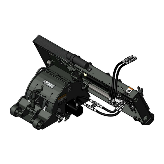
STANDARD FLOW
COLD PLANER
2800 N. Zeeb Rd., Dexter, MI. 48130, United States of America Copyright ©
Manual Number: MR05660
Part Number: LAF5412 & LAF5413
Date: September 2013
Rev. 2
Advertisement
Table of Contents

Summary of Contents for paladin FFC LAF5412
- Page 1 OPERATOR’S AND PARTS MANUAL STANDARD FLOW COLD PLANER Manual Number: MR05660 Serial Number: ___________________ Part Number: LAF5412 & LAF5413 Date: September 2013 Model Number: ___________________ Rev. 2 800-456-7100 I www.paladinattachments.com 2800 N. Zeeb Rd., Dexter, MI. 48130, United States of America Copyright ©...
- Page 2 Notes...
-
Page 3: Table Of Contents
TABLE OF CONTENTS PREFACE........................2 OWNER AND OPERATOR SAFETY INFORMATION SAFETY STATEMENTS ................... 3 GENERAL SAFETY PRECAUTIONS ............3-6 SAFETY SIGNS & DECALS ................7-8 INSTALLATION & SET-UP..................9-11 OPERATION ......................12 MAINTENANCE ....................13-15 PARTS........................16-24 CHASSIS ASSEMBLY..................16-17 HYDRAULIC ASSEMBLY................18-19 ROLLER ASSEMBLY..................20 SIDE SHIFT ASSEMBLY...................21 MOUNTING ASSEMBLY...................22... -
Page 4: Preface
PREFACE GENERAL INFORMATION This product was carefully designed and manufactured to give you many years of dependable service. Only minor maintenance (such as cleaning and lubricating) is required to keep it in top working condition. Be sure to observe all maintenance procedures and safety precautions in this manual and on any safety decals located on the product and on any equipment on which the attachment is mounted. -
Page 5: Safety Statements
SAFETY STATEMENTS THIS SYMBOL BY ITSELF OR WITH A WARNING WORD THROUGHOUT MANUAL IS USED TO CALL YOUR ATTENTION TO INSTRUCTIONS INVOLVING YOUR PERSONAL SAFETY OR THE SAFETY OF OTHERS. FAILURE TO FOLLOW THESE INSTRUCTIONS CAN RESULT IN INJURY OR DEATH. DANGER! THIS SIGNAL WORD IS USED WHERE SERIOUS INJURY OR DEATH WILL RESULT IF THE INSTRUCTIONS ARE NOT FOLLOWED PROPERLY. - Page 6 GENERAL SAfETy PRECAUTIONS GENERAL SAFETY PRECAUTIONS WARNING! PROTECT AGAINST fLyING DEbRIS always wear proper safety glasses, goggles, or a face shield when driving pins in or WARNING! PROTECT AGAINST FLYING DEBRIS out, or when any operation causes dust, flying debris, or any other hazardous mate- Always wear proper safety glasses, goggles or a face shield when driving pins in or rial.
- Page 7 GENERAL SAFETY PRECAUTIONS WARNING! DO NOT MODIFY MACHINE OR ATTACHMENTS Modifications may weaken the integrity of the attachment and may impair the function, safety, life, and performance of the attachment. When making repairs, use only the manufacturer’s genuine parts, following authorized instructions. Other parts may be substandard in fit and quality.
- Page 8 GENERAL SAFETY PRECAUTIONS WARNING! EXPOSURE TO RESPIRABLE CRYSTALLINE SILICA DUST ALONG WITH OTHER HAZARDOUS DUSTS MAY CAUSE SERIOUS OR FATAL RESPIRATORY DISEASE. It is recommended to use dust suppression, dust collection and if necessary personal protective equipment during the operation of any attachment that may cause high levels of dust.
- Page 9 SAFETY SIGN & DECAL LOCATIONS The diagram on this page shows the location of the decals used on the FFC Cold Planer. The decals are identified by their part numbers, with reductions of the actual decals located on the following page. Use this information to order replacements for lost or damaged decals. Be sure to read all decals before operating the attachment.
-
Page 10: Safety Signs & Decals
SAFETY SIGNS & DECALS PART #50-0721 WARNING! CRUSH HAZARD PART #41043 WARNING! HAZARDOUS DUST PART #50-10017 WARNING! READ MANUAL PART #RDL3100 WARNING! STAND CLEAR PART #50-0724 WARNING! HIGH PRESSURE FLUID PART #RDL3159 CAUTION! FLYING DEBRIS PART #RDL3179 LIFT POINT MR05660... -
Page 11: Installation & Set-Up
INSTALLATION & SET-UP WARNING! READ MANUAL PRIOR TO INSTALLATION Improper installation, operation, or maintenance of this equipment could result in serious injury or death. Operators and maintenance personnel should read this manual, as well as all manuals related to this equipment and the prime mover thoroughly before beginning installation, operation, or maintenance. - Page 12 INSTALLATION & SET-UP Hydraulic Connection READ AND UNDERSTAND ALL SAFETY STATEMENTS Read all safety decals and safety statements in all manuals before beginning any Cold Planer hydraulic connection. Know and obey all OSHA regulations, local laws, and other professional guidelines for your operation. Know and follow good work practices when assembling, maintaining, repairing, mounting, removing, or operating this equipment.
- Page 13 INSTALLATION & SETUP PLANER SETUP SAFETY FIRST! READ AND UNDERSTAND THE SAFETY INSTRUCTIONS SAFETY FIRST!! READ AND UNDERSTAND THE SAFETY INSTRUCTIONS (pages 2-4 of this BEFORE BEGINNING ANY COLD PLANER SETUP! manual) BEFORE BEGINNING ANY PLANER SETUP Setting planer depth: • Turn the depth jack (located on the front of the planer) to adjust planing depth.
-
Page 14: Operation
OPERATION Starting a Cut: To begin a cut, adjust the tilt and depth jacks to the desired tilt depth with the planer slightly above the ground. Engage the hydraulic system to start the drum. Lower the planer bringing the rear planer wheels onto the ground. -
Page 15: Maintenance
MAINTENANCE GENERAL INFORMATION Regular maintenance is the key to long equipment life and safe operation. Maintenance requirements have been reduced to the absolute minimum. However, it is very important that these maintenance functions be performed as described below. WARNING! Failure to obey the following procedures could result in death or serious injury. •... - Page 16 MAINTENANCE Lubrication Points Grease Fittings: Cylinder, 3 each, 6 Total Caster, 1 each, 4 Total Mounting, 4 Total ( 2 hidden behind mounting plate) Depth Arm, 2 Total NOTE: Lubricate all grease fittings with a NLGI #1 or 2 multipurpose grease or equivalent. IMPORTANT! Avoid excessive greasing.
-
Page 17: Parts
MAINTENANCE IMPORTANT! When replacing parts use only factory approved replacement parts. Manufacturer will not claim responsibility for use of unapproved parts or accessories and/or other damages as a result of their use. Park your prime mover on a level surface with this product properly attached. Place your prime mover’s transmission in “Park”... -
Page 18: Chassis Assembly
CHASSIS ASSEMBLY MR05660... - Page 19 CHASSIS ASSEMBLY Item Part Description 1. 07-3112 Fitting, Zerk, 1/4-28, Self-Tap 3. LAF9300 Weld, Chassis (12 inch) LAF9301 Weld, Chassis (16 inch) 5. LAF9302 Weld, Depth Arm (12 inch) LAF9302 Weld, Depth Arm (16 inch) 6. LAF9304 Weld, Jack Body 7.
-
Page 20: Hydraulic Assembly
HYDRAULIC ASSEMBLY RHW7906 RHW8138 LAF4717 MR05660... - Page 21 HYDRAULIC ASSEMBLY Item Part Description 1. 03-2182 Elbow, 45º, 12MB-12MF 2. 03-2291 Fitting, 6MB-6MF 3. 03-4368 Tee, 12MF-12MF-12FF 4. 03-5736 Cylinder, 1.5 x 1 x 24, 3.5K 5. 07-3022 Screw, HHC, Gr8, 1/4-20 x 2 6. LAF4076 Fitting, 12MB-12MF 7. LAF4697 Motor, Char-Lynn, 24 CC 8.
-
Page 22: Roller Assembly
ROLLER ASSEMBLY Item Part Description Item Part Description 1. LAF9310 Bearing, Deadshaft 13. LAF9389 Pick Holder (16 inch) 2. LAF9313 Hub, Weldment Pick Holder (18 inch) 4. LAF9314 Weld, Pick Pattern (12 inch) Pick Holder (20 inch) LAF9315 Weld, Pick Pattern (16 inch) Pick Holder (24 inch) 5. -
Page 23: Side Shift Assembly
SIDE SHIFT ASSEMBLY Item Part Description 1. 07-3112 Fitting, Zerk, 1/4-28, Self-Tap 2. LAF9304 Weld, Jack Body 3. LAF9309 Tube, Round, 1 x .687 x .85 5. LAF9317 Weld, Side Shift (12 inch) LAF9318 Weld, Side Shift (16 inch) 6. LAF9323 Weld, Jack Screw 7. -
Page 24: Mounting Assembly
MOUNTING ASSEMBLY Item Part Description 1. 13-50392 Rod, 2 X 47.25 3. LAF9319-0022 Weld, Plate, Universal (12 to 24 inches) 13-50434 Weld, Plate, Universal (30 to 36 inches) 5. LAF9326 Tool, Pick Removal 6. P100614 Bolt, Hex, 3/8 x 3 1/2, Gr5 7. -
Page 25: Rear Caster Assembly
REAR CASTER ASSEMBLY Item Part Description 1. 07-1764 Nut, Hex, Gr8, 1/2-13 2. 07-3112 Fitting, Zerk, 1/4-28, Self Tap 3. LAF9321 Weld, Wheel Bracket 4. LAF9322 Weld, Wheel 5. LAF9324 Pin, Dual, Snap Ring, 1-5.907 6. P851108 Washer, Lock, 1/2 7. -
Page 26: Labels & Decals
LABELS & DECALS Item Part Qty Description 1. 07-1714 Screw, HHC, Gr8, 5/16-18 x 1 2. 07-3624 Tack, Metal 3. 07-6869 Holder, Manual 4. 41043 Decal, Warning, Hazardous Dust 5. 50-0721 Label, Warning, Crush Hazard 6. 50-0724 Label, Warning, High Pressure Fluid 7. -
Page 27: Specifications
PRIME MOVER SPECIFICATIONS IMPORTANT Exceeding any of the maximum recommended prime mover specifications CAN result in damage to this product and WILL void all FFC warranties. DESCRIPTION SPECIFICATIONS Weight of Prime Mover without Cold Planer 11,000 lbs. maximum Operating Capacity of Prime Mover's Loader 4,500 lbs. -
Page 28: Bolt Torque
MR05660... -
Page 29: Product
Period, which is the period that begins on the fi rst to occur of: (i) the date of initial purchase by an end-user, (ii) the date the product is fi rst leased or rented, or (iii) the date that is six (6) months after the date of shipment by Paladin Light Construction as evidenced by the invoiced shipment date (the “Commencement Date”) and ends on the date...
Need help?
Do you have a question about the FFC LAF5412 and is the answer not in the manual?
Questions and answers