Table of Contents
Advertisement
Quick Links
Advertisement
Table of Contents

Related Manuals for optris Top-down GIS

Summary of Contents for optris Top-down GIS
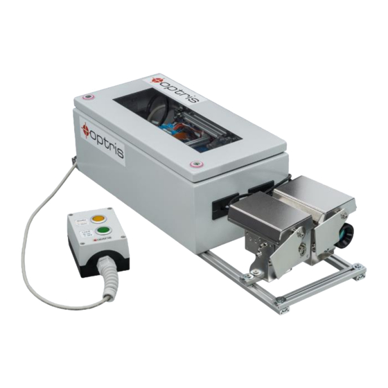
- Page 1 Operators Manual Top-down GIS Glass Inspection System...
- Page 2 Optris GmbH Ferdinand-Buisson-Str. 14 13127 Berlin Germany Tel.: +49 30 500 197-0 Fax: +49 30 500 197-10 E-mail: info@optris.global Internet: www.optris.global...
-
Page 3: Table Of Contents
Table of contents Table of contents ............................3 General notes ............................6 Intended use ..........................6 Warranty ............................7 Scope of supply ..........................8 Technical Data .............................9 Top-down GIS ..........................9 Factory default ..........................13 Optical specifications^ ........................ 15 2.3.1 Camera ..........................15 2.3.2 Pyrometer ........................... 18... - Page 4 Installation ............................20 Hardware installation ........................20 Software Installation ........................24 Electrical Installation ........................30 Operation ............................32 Maintenance ..........................35 Low-E measurement ........................36 Basics of glass measurement ......................37 Reflection and transmission ......................37 Influence of different measuring wavelengths ................39 Hardening of glass sheets ......................
- Page 5 Table of contents Appendix A – Control cabinet ......................... 43...
-
Page 6: General Notes
1 General notes 1.1 Intended use ® Thank you for choosing the optris Top-down Glass Inspection System (TDGIS). This compact system is ideal for measuring glass and can be used for process control in glass tempering machines. This system consists of several components which are already pre-wired and ready for immediate use. -
Page 7: Warranty
General notes 1.2 Warranty Each single product passes through a quality process. Nevertheless, if failures occur please contact the customer service at once. The warranty period covers 24 months starting on the delivery date. After the warranty is expired the manufacturer guarantees additional 6 months warranty for all repaired or substituted product components. -
Page 8: Scope Of Supply
1.3 Scope of supply ▪ PI 640i with 60° or 90° FOV ▪ CT G5 reference pyrometer with USB interface ▪ 2x Shutter systems with mounting bracket ▪ USB-Server Gigabit 2.0 ▪ Control cabinet (pre-assembled and pre-wired) ▪ Industrial Process Interface (PIF) ▪... -
Page 9: Technical Data
Technical Data 2 Technical Data 2.1 Top-down GIS Temperature range -20…900 °C Spectral range Reference sensor: 5 µm Imager: 8-14 µm Optical resolution 640x480 Pixel VGA Up to 800 points/line Accuracy ± 2°C or ± 2% Frame rate / Scan speed... - Page 10 Switch cabinet: 400 x 200 x 155 mm Weight Imager with shutter: 1.1 kg Sensor with shutter: 1 kg Control cabinet: 10 kg 13 kg (complete system) Material Stainless steal Warm-up time 10 min Table 1: Technical Data of Top-down GIS...
- Page 11 Technical Data Figure 1: Dimensions [mm], shutter system...
- Page 12 Figure 2: Dimensions [mm], switch cabinet...
-
Page 13: Factory Default
Technical Data 2.2 Factory default The CT G5L pyrometer is delivered with the following factory settings: Signal output object temperature 0-10 V Emissivity 0,920 Transmissivity 1,000 Averaging (AVG) 0,2 s Smart Averaging inactive Peak hold active (Hold time: 15 s) Valley hold Inactive Lower limit temperature range [°C]... - Page 14 (Output at OUT-AMB as 0-5 V signal on LT, G5 and P7) Baud rate [kBaud] You can change the settings either directly with the CompactConnect software or via the programming keys on the electronics box...
-
Page 15: Optical Specifications
Technical Data 2.3 Optical specifications^ 2.3.1 Camera Make sure that the focus of thermal channel is adjusted correctly. If necessary, focus the thermal imaging camera with the optics (Figure 3). The turning out of the optics leads to the focus setting "near"... - Page 16 PIX Connect has an algorithm which corrects this distortion. As an alternative to the tables below, the optics calculator can also be used on the optris website or via the optris calculator app. The app can be downloaded for free from the...
- Page 17 Technical Data * Note: The accuracy of measurement can be outside of the specifications for distances below the defined minimum distance.
-
Page 18: Pyrometer
The distance is always measured from the front edge of the sensing head. As an alternative to the optical diagrams, the spot size calculator can also be used on the Optris website or via the Optris calculator app. The app can be downloaded for free from the Google Play store (see QR code). - Page 19 Technical Data CT G5L (SF optics)
-
Page 20: Installation
3 Installation 3.1 Hardware installation Basically the whole system consists of three main components: ▪ Temperature measuring system 1: Camera with shutter (measurement from above) ▪ Temperature measuring system 2: Reference pyrometer with shutter (measurement from below) ▪ Switch cabinet with complete electronic unit and control unit Hardware and software recommendations: ▪... - Page 21 Installation there is a small slot there, which allows a contactless temperature measurement. The glass is transported on conveyor belts. Figure 4 shows a classical glass tempering process. Figure 4: Process of glass production After leaving the furnace, the glass must be cooled down after a relatively short time. The annealing furnace follows the heating furnace at a very short distance.
- Page 22 slight inclination of the camera is advantageous. More about this in chapter 5 Basics of glass measurement. The software PIX Connect uses the Linescan function to display a complete image although only one line is scanned. • When installing the CT G5 sensor, make sure that it is positioned so that the optical beam path runs between the individual rollers.
- Page 23 Installation Now that the three main components have been successfully assembled, two connections must be connected. The first connection is the Ethernet cable to a computer or switch. The second connection is the power supply. The entire system is supplied with 24 V. The power supply unit is included in the delivery. Another component of the system is the control unit.
-
Page 24: Software Installation
3.2 Software Installation After having connected your Hardware, you can start with the configuration in the PIX Connect software. Now that you have successfully connected your hardware, you can start with the configuration in the PIX Connect software. But before you can do this, you must first set up the USB server. On the supplied USB stick, in the folder USB Sever, you will find two software programs (WuTility and USB Redirector) that are required for this. - Page 25 GIS Demo”. You can load these layouts in the menu under Tools and Load layout and use it as a presetting. The layout named "Top-down GIS Demo" is used for demonstration and is set to be used for temperatures from -20 to 900 °C.
- Page 26 Now a few settings must be made. First, the scan line must be positioned correctly. Make sure that the width of the scan line is at least as wide as the glass that passes through it. This ensures that the entire glass is scanned. The scan line can be changed directly in the lower left window (Line scanner live view).
- Page 27 Installation Figure 8: Position of measure area Ext. Ref-Sensor G5 The linescan is displayed in a metric format. The furnace is displayed in its dimension. This means that the length and width of the furnace must be specified in the software. To do this, go to the menu Tools, Line scanner mode and select Line scanner settings.
- Page 28 Figure 9: Line scanner configuration Under Width (Length of line) and Length (of scan) the two parameters can be entered. To obtain an undistorted representation of the product at the end of a linescan, the Feed rate of the furnace is still required. This must also be entered.
- Page 29 Installation With the new specification of these values, the calculated area must still be adjusted. This indicates how much material is generated in one scan pass. To do this, go to Tools and Configuration in the menu. In the tab Measuring area click on the measuring area Area.
-
Page 30: Electrical Installation
3.3 Electrical Installation The delivered glass system is already pre-wired and is ready for operation without additional electrical installation. To integrate the input signal from the furnace with the glass inspection system, you must open the control cabinet. On the left side is a terminal block, which is connected to different colors of wires. - Page 31 Installation Designation 1. Ground 2. Shutter Status LED 3. Digital Input for Low-E measurement 4. Analog Input for opening/closing the shutters 5. 24 V Power supply 6. 24 V Power supply 7. 24 V Power supply 8. Ground 9. Ground 10.
-
Page 32: Operation
4 Operation After successful hardware and software configuration and electrical installation, the operation of the system is very simple. With the existing layout and the signal of the furnace, the system runs autonomously. The process procedure is as follows: The glass system gets the signal from the furnace: the signal opens the two shutters and the actual process starts. - Page 33 Operation Furthermore, the amount of glass produced can be displayed in the software. In this way, it is possible to see how much glass has been produced in a linescan pass. This information can be found in the digital display group. Figure 14: Digital display group Another component of the system is the control unit.
- Page 34 Figure 16: Linescan in PIX Connect software...
-
Page 35: Maintenance
Operation 4.1 Maintenance The system requires a maintenance check at regular intervals. Here, it should be checked whether the optics of the camera are clean, correctly focused and whether the shutter systems still function properly. This includes a complete opening and closing of the shutters. These points must be observed, as they have a direct influence on the temperature measurement. -
Page 36: Low-E Measurement
For this purpose, there is a button labeled Low- E on the control unit. If this button is pressed in the "Top-down GIS" layout, the temperature range changes to 0-250 °C. In this range it is then possible to measure Low-E glass. -
Page 37: Basics Of Glass Measurement
Basics of glass measurement 5 Basics of glass measurement In general, non-contact temperature measurement on glass is very suitable. However, the following points should be considered: • Angle of view • Emissivity • Coatings • Correct sensors • Heat and dust Also pay attention to the measuring depths: •... - Page 38 Representation of the emissivity over the wavelength for different glass types Figure 21: The figure shows how the dependence of the emissivity of different types of glass behaves with respect to the wavelength. A good emissivity is present in the wavelength range 5.0 µm and 7.9 µm and is preferred for measurements on glass.
-
Page 39: Influence Of Different Measuring Wavelengths
Basics of glass measurement 5.2 Influence of different measuring wavelengths Spectral range Sensor (Examples) Purpose 8 - 14 µm PI 640i, Xi 400 Low temperature, uncoated glass 7.9 µm PI 640i G7, CTlaser G7 High temperature, coated glass 5.0 µm CTlaser G5 molten glass, 1.0 µm... -
Page 40: Hardening Of Glass Sheets
5.3 Hardening of glass sheets • Temperature has a direct influence on glass quality • Testing for the heating profile (temperature distribution) Linescan function (line scanning) with PI camera from above and reference measurement with pyrometer from below. Direct effects: Defective or inhomogeneous surfaces can be detected by the measurement. Tempering: Change of the heating/cooling degree depending on the temperature distribution 5.4 Referencing from below Referencing from below is necessary because Low-E glass is used in a glass tempering system. -
Page 41: Angle Dependency
Basics of glass measurement • No to little space for cameras to measure from below due to the low furnace height of the system. This would require more than one camera and the wide angle has a different influence. 5.5 Angle dependency The angle dependence is another important factor to be considered when measuring temperature. - Page 42 Figure 22: Angle dependency of Low-E glass, coated Figure 23: Angle dependency of Low-E glass, uncoated surface surface...
- Page 43 Appendix A – Control cabinet Appendix A – Control cabinet Figure 24: Wiring diagram of control cabinet...
- Page 44 Power supply: 12-24 V Upper terminal screw Connection for Process Interface (PIF) Switch for different operation modes: S1: Switching between switch operation and pulse operation S2: Activation/deactivation of fast- closing mode S3: Only for factory calibration (Switch must be at Normal) S4: Switching between mV or mA input Figure 25: Control box of shutter (opened) Lower screw terminal: Connection for power supply,...
- Page 45 Appendix A – Control cabinet Pin assignment PIF electronic box (industrial process interface) GREY Interrupt GREEN SCL (I²C) YELLOW SDA (I²C) WHITE 3.3 V BROWN SHIELD Figure 26: Connections of the industrial Process Interface (PIF)
- Page 46 The industrial process interface provides the following inputs and outputs: Name Description max range / status A IN 1 / 2 Analog input 1 and 2 0-10 V D IN 1 Digital input 24 V (active-low = 0…0,6 V) AO1 / 2 / 3 Analog output 1, 2 and 3 0/4-20 mA Alarm output 1, 2 and 3...
- Page 47 Appendix A – Control cabinet Designation CT electronic box +8…36 VDC Power supply Ground (0 V) of power supply Ground (0 V) of internal in- and outputs OUT-AMB Analog output head temperature (mV) OUT-TC Analog output thermocouple (J or K) OUT-mV/mA Analog output object temperature (mV or mA) F1-F3...
Need help?
Do you have a question about the Top-down GIS and is the answer not in the manual?
Questions and answers