Table of Contents
Advertisement
Quick Links
INSTALLATION and OPERATING
INSTRUCTION MANUAL
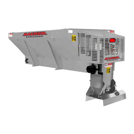
V-BOX MATERIAL SPREADERS
SAFETY ALERT ...............................................................................................................
INSTALLATION & ASSEMBLY INSTRUCTIONS .............................................................
ELECTRIC THROTTLE CONTROLS ................................................................................
CENTER HIGH MOUNT STOP LAMP ...............................................................................
SPREADER MAINTENANCE ............................................................................................ 15
SPREADER PARTS LISTS & EXPLODED VIEW
• HONDA ENGINE SPREADERS .................................................................................... 16
• BRIGGS & STRATTON ENGINE SPREADERS ............................................................ 22
• SUPERIOR GEARBOX ASSEMBLY .............................................................................. 28
• SPINNER ASSEMBLY
•• SHORT ............................................................................................ 30
•• EXTENDED ..................................................................................... 34
•• HONDA ENGINE ............................................................................. 36
•• BRIGGS & STRATTON ENGINE .................................................... 37
• CONTROL BOX ............................................................................................................. 38
• OPTIONAL COMPONENTS .......................................................................................... 40
• PARTS LIST SHIPPING CARTON ................................................................................ 41
• PARTS LIST REAR FORKLIFT ASSY ........................................................................... 42
WIRELESS CONTROLLER INSTRUCTIONS .................................................................. 43
NAME PLATE INFORMATION .......................................................................................... 46
WARRANTY INFORMATION ............................................................................................. 47
Part No. 00122-152-01 Rev. B
September 25, 2008
PV SERIES
INDEX
1
2
3
-
4
5
-
6
7
-
8
9
- 14
- 21
- 27
- 29
- 31
- 33
- 35
- 39
- 41
- 45
Advertisement
Table of Contents

Related Manuals for Magnum V-BOX PV Series

Summary of Contents for Magnum V-BOX PV Series
-
Page 1: Table Of Contents
INSTALLATION and OPERATING INSTRUCTION MANUAL V-BOX MATERIAL SPREADERS PV SERIES INDEX SAFETY ALERT ....................... INSTALLATION & ASSEMBLY INSTRUCTIONS ............. ELECTRIC THROTTLE CONTROLS ................CENTER HIGH MOUNT STOP LAMP ................CLUTCH BURNISHING ....................SPREADER OPERATION ....................10 - 14 SPREADER MAINTENANCE .................... 15 SPREADER PARTS LISTS &... -
Page 2: Safety Alert
THE BEST SAFETY DEVICE IS A CAREFUL OPERATOR! SAFETY ALERT SYMBOL ATTENTION! THIS SYMBOL MEANS BECOME ALERT! YOUR SAFETY IS INVOLVED! PLEASE READ AND UNDERSTAND COMPLETELY BEFORE DOING! SAFE EQUIPMENT INSTALLERS and OPERATORS: TURN OFF ALL POWER BEFORE PERFORMING ANY SERVICE OPERATIONS •... -
Page 3: Installation & Assembly Instructions
INSTALLATION AND ASSEMBLY INSTRUCTIONS INSTALLATION INSTRUCTIONS: The 1.8 and 2.0 Series Spreaders can mount and store as a single unit and will mount on most medium, heavy-duty/pick-up trucks as well as 1 ton trucks WARNING THE SPREADER UNIT MUST BE SECURELY FASTENED TO THE VEHICLE. FAILURE TO NOT PROPERLY RESTRAIN THE UNIT COULD PERMIT THE UNIT TO BREAK FREE FROM THE TRUCK AND CREATE A POTENTIAL FOR A LIFE THREATENING ACCIDENT. - Page 4 OPTIONAL HOLD-DOWN KIT Part No. (62562) ITEM PART NUMBER QTY. DESCRIPTION 62602 Ratchet/Strap 62807 Bolt, 1/2” Eye 20307 Locknut, 1/2-13 Esna ZP 62604 Nut, 1/2-13 Hex ZP 62605 Flatwasher, 3/4" INSTALLATION INSTRUCTIONS CAUTION READ ALL THE INSTALLATION INSTRUCTIONS BEFORE STARTING Before starting, verify that this mounting is acceptable to the vehicle manufacturer.
-
Page 5: Electric Throttle Controls
INSTALLATION INSTRUCTION FOR ELECTRIC THROTTLE CONTROLS (FACTORY INSTALLED ACTUATORS) WARNING BEFORE BEGINING ANY INSTALLATION ON THIS UNIT, disconnect the spreader battery negative cable if already installed. PREPARING UNIT: Spreaders with factory installed throttle controls do not require installer hook-up to the engine. The actuator has been installed and tested at the factory. - Page 6 WARNING USE SAFETY GLASSES OR OTHER FACE PROTECTION AGAINST POSSIBLE BATTERY EXPLOSION. DO NOT SMOKE AND AVOID OTHER SOURCES OF IGNITION. Attach the positive battery cable (each end should have a rubber boot) to the positive terminal of the battery. Make sure these protective boots are covering the positive terminal post on the battery and on the solenoid.
-
Page 7: Center High Mount Stop Lamp
CENTER HIGH MOUNT STOP LAMP (CHSML) WARNING Federal Motor Vehicle Safety Standards require all Trucks, Buses, and Multipurpose passenger vehicles, manufactured on or after September 1, 1993, with a gross vehicle weight rating (GVWR) of 10,000 lbs. or less and overall width less than 80" must be equipped with a Center Height Mount Stop Lamp (CHMSL). - Page 8 CENTER HIGH MOUNTING STOP LIGHT ITEM PART NUMBER QTY. DESCRIPTION 62097 Kit, Center High Mount Stop Light 62714 • Lamp, Stop 62715 • Grommet 62364 • Cable, Light Power 62738 • Cable, Stop Lamp 62283 • Weld, Stop Lamp Bracket - Hydraulic Units ONLY 62739 •...
- Page 9 5. Run the engine at 75% throttle. 6. Engage and disengage the clutch 25 times, 10 seconds “ON” and 10 seconds “OFF”. Magnum recommends 15-20 ft-lbs of torque on pulley assembly screws (5/16-18UNC) and 20-30 ft-lbs of torque on shaft fixing screw.
- Page 10 SPREADER OPERATION Wireless Throttle Control Button Functions (Sequence of Operations) Stop Choke / Throttle Fast Start Conveyor Throttle Slow A. ON/Off System power activated (ready to F. TO TURN ENGINE OFF (With or without conveyor start). Spreader engine not running. running).
- Page 11 SPREADER OPERATION Electric Throttle Control Panel Switch Functions (Optional) (Sequence of Operations) WARNING Electric Throttle Control Panel Switch Functions (Optional) (Sequence of Operations) Electric Throttle Control Panel Switch Functions Cont. A. ON/OFF System power activated (ready to start). Spreader engine is not running. Spreader conveyor is not engaged.
- Page 12 SPREADER OPERATION E. TO DISENGAGE Spreader Conveyor. Tap START switch momentarily so that red indicator light goes out. Do not fully depress the START switch, only half way is needed. Only the conveyor stops, the engine continues to run. F. TO TURN ENGINE OFF (with or without conveyor running). Depress LO on throttle control to reduce setting to idle (this prevents engine flooding and hard starting).
- Page 13 SPREADER OPERATION A. Start the engine and engage the clutch. The amount of material spread, depends on engine speed and gate opening. Decreasing RPM and/or gate height will decrease amount spread; the inverse holds true also. Notice that the electric clutch can be engaged or disengaged at any time and at any engine RPM. However, since engagement time and torque is almost instantaneous, to prevent premature spinner chain failure and chain tension loss, it is recommended that the electric clutch be engaged at the lowest possible RPM without stalling the engine.
- Page 14 June, 2000 SERVICE BULLETIN NO. 178 1.8, 2.0 and MDV Insert Hopper Spreader Briggs & Stratton Corporation and Honda Engine Motor of America have stated in their manuals: DO NOT TRANSPORT ENGINE WITH FUEL IN TANK OR WITH FUEL SHUT-OFF VALVE OPEN. Failure in doing this may cause the engine crankcase to fill with fuel.
- Page 15 MAINTENANCE WARNING DO NOT ATTEMPT TO LIFT THE SPREADER BY THE CENTER LIFT OR CORNER LIFT HOOKS WITH MATERIAL IN THE SPREADER. BEFORE BEGINNING ANY MAINTENANCE ON SPREADER, DISCONNECT SPREADER BATTERY LEADS. Grease idler bearings on idler shaft takeup assembly, outboard bearing on gearbox output shaft, and both spinner bearings every ten hours of operation.
- Page 17 PARTS LIST FOR ENGINE DRIVEN HOPPER ASSEMBLY (Stainless Steel) Honda 50” Wide/One Piece Top Screen 2.0 Cu. Yd. (65003) ITEM PART NUMBER QTY. DESCRIPTION 63824 Weld, PV 8’ Hopper (2.0 Cu. Yd.) 63301 Locknut, 5/16”-18 Nylon Insert, SS 63309 Lockwasher, 5/16” Medium Split, SS 62641 Nut, 5/16”-18 Serrated Flange, SS 63180...
- Page 19 62691 Pin, 1//8” X 1” Cotter, SS 63845 Decal, Magnum Logo 62009 Decal, Danger Conveyor 62768 Decal, Gasoline Only 63846 Decal, Magnum Serial Tag 62007 Decal, Caution 00122-152-01 Instructional Manual, Magnum PV 63128 2 Ft. Trim, Vinyl 62364 Cable, Light Power...
- Page 21 PARTS LIST FOR ENGINE DRIVEN HOPPER ASSEMBLY (Stainless Steel) Honda 50” Wide/One Piece Top Screen 2.0 Cu. Yd. (65003) (Continued) ITEM PART NUMBER QTY. DESCRIPTION 62702 Plug, Drain (Honda Tapped) 62720 Linkage, Throttle 62718 Bracket, Actuator, Honda 62719 Lever, Extension, Honda Throttle 63843 Assy, Lift Rear Forklift PV CS 63174...
- Page 23 PARTS LIST FOR ENGINE DRIVEN HOPPER ASSEMBLY (Stainless Steel) Briggs & Stratton 50” Wide/One Piece Top Screen 2.0 Cu. Yd. (63808) ITEM PART NUMBER QTY. DESCRIPTION 63823 Weld, PV 8’ Hopper (2.0 Cu. Yd.) 63301 Locknut, 5/16”-18 Nylon Insert, SS 63309 Lockwasher, 5/16”...
- Page 25 62691 Pin, 1//8” X 1” Cotter, SS 63845 Decal, Magnum Logo 62009 Decal, Danger Conveyor 62768 Decal, Gasoline Only 63846 Decal, Magnum Serial Tag 62007 Decal, Caution 00122-152-01 Instructional Manual, Magnum PV 63128 2 Ft. Trim, Vinyl 62364 Cable, Light Power...
- Page 27 PARTS LIST FOR ENGINE DRIVEN HOPPER ASSEMBLY (Stainless Steel) Briggs & Stratton 50” Wide/One Piece Top Screen 2.0 Cu. Yd. (63808) (Continued) ITEM PART NUMBER QTY. DESCRIPTION 62725 Clamp, Rod Prop 62644 Decal, Engine Warranty 62643 Decal, Fuel Shut-Off 62646 Screw, #10-32 PPH Machine 63165 Motor, Actuator...
-
Page 28: Superior Gearbox Assembly
SUPERIOR GEARBOX ASSEMBLY... - Page 29 PARTS LIST FOR SUPERIOR GEARBOX ASSEMBLY (63419) ITEM PART NUMBER QTY. DESCRIPTION 63849 Housing 63850 Cover 63851 End Cap 63852 End Cap, Thru 63853 Shaft, Output 63854 Shaft, Input 63855 Gear, Wheel, LH 63856 Gear, Worm, LH 63857 Bearing, Input Cup 63858 Bearing, Input Cone 63859...
- Page 30 SHORT SPINNER ASSEMBLY 18 REF. 17 REF. DANGER CAUTION DETAIL - A 12 - 13...
-
Page 31: Short
PARTS LIST FOR SPINNER ASSEMBLY SHORT - PARTS ONLY (ORIGINAL VERSION OF STANDARD) ITEM PART. NO. QTY. DESCRIPTION 62506 Short (SS) Spinner Assy. 62779 • Weld, Spinner Frame (Stainless Steel) 61151 • Shaft, Spinner, 24” Long 62146 • Disc, Poly Spinner 62356 •... -
Page 33: Intermediate "Standard
PARTS LIST FOR EXTENDED SPINNER ASSEMBLY INTERMEDIATE - STANDARD (NEW) ITEM PART NUMBER QTY. DESCRIPTION 63816 Standard (SS) Spinner Assy. 63829 • Weld, Spinner Frame (Stainless Steel) 62933 • Shaft, Spinner, 30” Long 62146 • Disc, Poly Spinner 62356 • Bearing 63819 •... - Page 34 EXTENDED SPINNER ASSEMBLY DANGER CAUTION 16 REF. 17 REF. DETAIL- A DETAILS - A 12 - 13...
-
Page 35: Extended
PARTS LIST FOR EXTENDED SPINNER ASSEMBLY EXTENDED - PARTS ONLY ITEM PART NUMBER QTY. DESCRIPTION 62507 Extended (SS) Spinner Assy. 62793 • Weld, Spinner Frame (Stainless Steel) 62057 • Shaft, Spinner, 36” Long 62146 • Disc, Poly Spinner 62356 • Bearing 63819 •... -
Page 36: Electric Controls
ELECTRIC CONTROLS PARTS & SCHEMATIC HONDA ACTUATOR ITEM PART NUMBER QTY. DESCRIPTION 62721 Actuator 62801 Flatwasher, #10 SS 62800 Lockwasher, #10, SS 62799 Bolt, M5 X 25 HH, SS 63166 Cable, Control - Spreader 63167 Cable, Control - Truck 62040 Cable, Battery - Black 63130 Cable, Battery - Red... - Page 37 ELECTRIC CONTROLS PARTS & SCHEMATIC BRIGGS & STRATTON ACTUATOR ITEM PART NUMBER QTY. DESCRIPTION 63165 Actuator 63166 Cable, Control - Spreader 63167 Cable, Control - Truck 61179 Solenoid, Grounded 61213 Cable, Starter 63168 Clutch, Electric 63164 Motor, Actuator 62648 Linkage, Throttle 62645 Bracket, Actuator (Briggs &...
-
Page 38: Control Box
CONTROL BOX (OPTIONAL) - Page 39 PARTS LIST FOR CONTROL PANEL ASSEMBLY (OPTIONAL) (62334) ITEM PART NUMBER QTY. DESCRIPTION 62150 Enclosure 62670 Panel 62153 Switch, START/CONV 62154 Switch, Choke HI/LO 62155 Switch, ON/OFF 62158 Enclosure, Back Panel 62159 Screw, #8 x 1/2 SM SLT HWH ZP 62156 Conn., double M/FM 62161...
- Page 40 22"...
-
Page 41: Parts List Shipping Carton
AUXILARY COMPONENTS ITEM PART NUMBER QTY. DESCRIPTION 63184 Inverted Vee 8 ft. (Carbon Steel) 63201 Weldment, Screen (8 Ft.) One Piece Screen 62145 6” Extension (Stainless Steel - 8 Ft. Unit) Kit PARTS LIST FOR SHIPPING CARTON (63302) ITEM PART NUMBER QTY. - Page 42 PARTS LIST FOR REAR FORKLIFT ASSEMBLY Item Part Number Qty. Description 63839 Bracket, Fork Front LH, CS 63841 Bracket, Fork Front RH, CS 62697 Bolt, 3/8-16 X 1, HH 62743 Nut, 3/8-16 Hex Flange 63847 Decal, Caution Unloaded 63848 Decal, Caution 4” Min...
-
Page 46: Name Plate Information
NAME PLATE INFORMATION... - Page 48 MAGNUM SPREADERS 18513 EUCLID AVE. CLEVELAND, OH 44112-1084 PHONE: (216)486-1313 Website: www.magnumspreaders.com IMPORTANT INFORMATION ENCLOSED...
Need help?
Do you have a question about the V-BOX PV Series and is the answer not in the manual?
Questions and answers