Table of Contents
Advertisement
Quick Links
Advertisement
Table of Contents

Related Manuals for Clear-Com 4000 II Series

Summary of Contents for Clear-Com 4000 II Series
- Page 1 4000 Series II Technical Manual Issue 2.1 June 2006...
- Page 3 4000 Series II Thank you for purchasing this product; we hope it will provide many years of reliable and rewarding service. We would be pleased to hear from you if you have any difficulties, comments or suggestions related to this product, the user documentation or the support service which we offer. Please feel free to contact us by e-mail, postal mail or telephone.
- Page 4 Technical Manual Issue 2.1 4000 Digital Series Page ii STA0381...
- Page 5 General Enquiries: Tel: +44 (0) 1223 815000 Fax: +44 (0) 1223 815001 email: vgc.uk@vitecgroup.com EMEA Sales: Tel: +44 (0) 1223 815000 Orders: Fax: +44 (0) 1223 815001 email: customerservicesUK@vitegroup.com Support: Tel: +49 (0) 40 6688 4040 (day) Tel: +49 (0) 40 6688 4041 (night) Fax: +49 (0) 40 6688 3055 (repairs) vitec.support@avc.de (repairs) vitec.support@avc.de (support)
- Page 6 Technical Manual Issue 2.1 4000 Digital Series Page iv STA0381...
- Page 7 Policy Statement Vitec Group Communications has a policy of continuous improvement of both products and documentation and reserves the right modify product specifications and characteristics without notice, at any time. Vitec Group Communications has endeavoured to ensure that information, details and descriptions set out in this document are correct at the time of publication.
- Page 8 Technical Manual Issue 2.1 4000 Digital Series Page vi STA0381...
- Page 9 Revision History Issue Date Notes April 2000 Initial Issue June 2006 Updates 4000 Digital Series Issue 2.1 Technical Manual STA0381 Page vii...
- Page 10 Technical Manual Issue 2.1 4000 Digital Series Page viii STA0381...
- Page 11 Warnings and Cautions GENERAL WARNING Electrical shock can cause severe personal injury or death. All major units of this equipment are powered by mains voltage. Unless specifically advised otherwise, DISCONNECT mains supply before carrying out any maintenance or repair tasks. This equipment contains electrostatic sensitive devices.
- Page 12 Technical Manual Issue 2.1 4000 Digital Series Page x STA0381...
- Page 13 Glossary of Terms Analogue to Digital Converter Assignment, Diagnostics and Monitoring Standard co-axial video connector CAT5 Cable standard for high speed data communica- tions (e.g. 100Base-TX) CODEC Coder/Decoder CMAPSi Configuration and Master Assignment Program- ming System integrated Central Switching Unit Digital to Analogue Converter Direct Access Key Decibel...
- Page 14 Non Intrusive Download NVRAM Non-Volatile Random Access Memory Output Printed Circuit Board Pot. Potentiometer Power Supply Unit Random Access Memory Rear Connector Unit RJ45 Standard connector for data communications (used with CAT5 cabling for comms. between the matrix and control panels) Root Mean Square Standard Rack Unit (19 inches wide x 1.75 inches high or 482.6mm x 44.45mm)
- Page 15 Consult the named Vitec Group Communications document for further details. Contact Vitec Group Communications for suitable options. Tips given. 4000 Digital Series Issue 2.1 Technical Manual STA0381 Page xiii...
- Page 16 Technical Manual Issue 2.1 4000 Digital Series Page xiv STA0381...
-
Page 17: Table Of Contents
TABLE OF CONTENTS 1 Introduction ......................1 1.1 Scope ........................1 1.2 System Overview ..................... 1 2 Control Panel Description ..................3 2.1 Overview ........................3 2.2 Standard Control Panels ..................4 2.2.1 PD4215R/4215 - 16 Key Control Panel (1RU) .............. 4 2.2.1.1 PD4215R Front View.................... - Page 18 2.2.10.3 PD4226 Rear View ..................... 29 2.2.10.4 PD4226R/PD4226 Components................. 29 2.2.11 PD4221 LCD Key Panel (2RU) .................. 31 2.2.11.1 PD4221 Front View .................... 31 2.2.11.2 PD4221 Rear View ..................... 31 2.2.11.3 PD4221 Components ..................32 2.2.12 PD4222R/PD4222 LCD Key Panel and Rotary Encoder (2RU) ........ 33 2.2.12.1 PD4222R Front View..................
- Page 19 3.1 PDE 4505 Key extension card ................59 3.2 PDE 4530 LCD switch driver card ................. 59 3.3 PDE 4531 1U LCD Key Card ................. 59 3.4 PDE 4532 2U LCD Key Card ................. 60 3.5 PDE 4533 Key/Pot. Card ..................60 3.6 PDE 4534 RJ45 Connector Card ................
- Page 20 4.8 PDE4663B - Central Processor RCU Card ............88 4.8.1 Card location ........................ 89 4.8.2 Links ..........................89 4.8.3 Connector details ......................89 4.8.4 PDE4645 - Optional GPI card ..................92 4.8.5 PDE 4628 - Serial Communications Rear Connector Unit (SCRCU) ......92 4.8.5.1 Card Location .......................
- Page 21 List of Figures Figure 1 - PD4215R Front View ....................4 Figure 2 - PD4215 Front View ....................5 Figure 3 - PD4215R/PD4215 Rear View .................. 5 Figure 4 - PD4217 Front View ....................7 Figure 5 - PD4217 Rear View ....................7 Figure 6 - PD4211 Front View ....................
- Page 22 Figure 46 - PD4230R Front View ................... 56 Figure 47 - PD4231R Front View ................... 57 Figure 48 - PD4231R Rear View .................... 57 Figure 49 - PDE4505 Key Extension card ................59 Figure 50 - PDE4530 LCD Switch Driver Card ..............59 Figure 51 - PDE4531 LCD Key Card ..................
- Page 23 List of Tables Table 1: PDE 3531 Connector Information ................17 Table 2: PDE4631 LEDs......................74 Table 3: PDE4606B LEDs ....................... 78 Table 4: PDE4663 - GPI Inputs ....................85 Table 5: PDE4663 - GPI Outputs..................... 86 Table 6: PDE4663 - Ethernet RJ45 ..................87 Table 7: PDE4663 - Serial 1 and 2...................
- Page 24 Installation Guide Issue 1.6 4000 Digital Series Page ii STA0379...
-
Page 25: Introduction
1 Introduction 1.1 Scope This manual describes Vitec Group Communications Voice Communications System (VCS) for Broadcast applications and gives details of individual components and sub-assemblies. Specific systems may not contain all the components listed in this manual and the quantities present may vary. Some third party components or equipment may also be used in Broadcast systems. - Page 26 4000 Digital Series systems can also be achieved by use of Ethernet, providing an integrated private intercom network. Up to eight 4000 Digital Series systems can be connected using this facility. A Conference facility is also available, configured via CMAPSi, which allows people to converse in a conference mode.
-
Page 27: Control Panel Description
2 Control Panel Description 2.1 Overview The 4000 Series II Control Panels comprise of a range of 1RU and 2RU by 19 inch rack mount units. The standard connection of these panels is via CAT5 (RJ45) cabling to connect analogue audio and RS422 data from the Control Panel to the PDE4628 Serial Communications RCU located in the Matrix. -
Page 28: Standard Control Panels
2.2 Standard Control Panels 2.2.1 PD4215R/4215 - 16 Key Control Panel (1RU) 2.2.1.1 PD4215R Front View Microphone Socket Direct Access Key (DAK) Microphone Mute Pushbutton and LED DAK Indicator LED Designation Strip Headset Select Pushbutton and LED Loudspeaker Aperture Headset Socket Auxiliary Volume Control and LED Reply Key Volume Control and LED... -
Page 29: Pd4215 Front View
2.2.1.2 PD4215 Front View Microphone Socket Main Volume Control Direct Access Key (DAK) Loudspeaker Talk Tally LED Headset Socket Listen Tally LED Headset Select Pushbutton Designation Strip Auxiliary Volume Control Microphone Mute Pushbutton Reply Key Figure 2 - PD4215 Front View 2.2.1.3 PD4215R/PD4215 Rear View Earth Connection Matrix Comms Connector (BNC) (Optional) -
Page 30: Pd4215R/Pd4215 Components
2.2.1.4 PD4215R/PD4215 Components 4215 CONTROL PANEL PDE 4535 PROCESSOR CARD PDE 4553 16 KEY SWITCH CARD PDE 4537 AUDIO/CONTROL I/O OPTIONS CARD PDE 4536 COAX/FIBRE OPTIC OPTIONS CARD Mechanical construction and wiring are shown in the associated drawings. Technical Manual Issue 2.1 4000 Digital Series Page 6... -
Page 31: Pd4217 - Intelligent Control Panel (1Ru)
2.2.2 PD4217 - Intelligent Control Panel (1RU) 2.2.2.1 PD4217 Front View Microphone Socket Headset Socket Soft Mode Pushbutton Headset Select Pushbutton Shift Pushbutton Microphone Mute Pushbutton Rotary LED Display Level Control Pushbutton Talk Tally LED Loudspeaker Cut Pushbutton Listen Tally LED Rotary Encoder Alphanumeric LED Display Direct Access Key (DAK) -
Page 32: Pd4217 Components
2.2.2.3 PD4217 Components 4217 CONTROL PANEL PDE 4535 PROCESSOR CARD PDE 4556/4557 SWITCH/DISPLAY CARDS PDE 4537 AUDIO/CONTROL I/O OPTIONS CARD PDE 4536 COAX/FIBRE OPTIC OPTIONS CARD Mechanical construction and wiring are shown in the associated drawings. Technical Manual Issue 2.1 4000 Digital Series Page 8 STA0381... -
Page 33: Pd4211 Lcd Key Panel (1Ru)
2.2.3 PD4211 LCD Key Panel (1RU) 2.2.3.1 PD4211 Front View Microphone Socket Soft Pushbutton Level Control Auxiliary Volume Control Shift Pushbutton Main Volume Control Microphone Mute Pushbutton Reply Key Loudspeaker Direct Access Key (DAK) Headset Select Pushbutton Headset Socket Figure 6 - PD4211 Front View NOTE: Microphone is shown here for illustrative purposes only. -
Page 34: Pd4211 Components
2.2.3.3 PD4211 Components 4211 CONTROL PANEL PDE 4535 PROCESSOR CARD PDE 4530/4531/4533 LCD SWITCH/POT CARDS PDE 4537 AUDIO/CONTROL I/O OPTIONS CARD PDE 4536 COAX/FIBRE OPTIC OPTIONS CARD Mechanical construction and wiring are shown in the associated drawings. Technical Manual Issue 2.1 4000 Digital Series Page 10 STA0381... -
Page 35: Pd4212R/Pd4212 Lcd Key Panel And Rotary Encoder
2.2.4 PD4212R/PD4212 LCD Key Panel and Rotary Encoder 2.2.4.1 PD4212R (revised) Front View Microphone Socket Main Volume Control Microphone Mute Pushbutton Reply Key Shift Pushbutton Direct Access Key (DAK) Crosspoint Level Control Soft Pushbutton Loudspeaker Headset Select Pushbutton Auxiliary Volume Control Headset Socket Figure 8 - PD4212R (revised) Front View 2.2.4.2 PD4212R Front View... -
Page 36: Pd4212 Front View
Crosspoint Level Control Soft Pushbutton Loudspeaker Headset Select Pushbutton Auxiliary Volume Control Headset Socket Figure 9 - PD4212R Front View 2.2.4.3 PD4212 Front View Microphone Socket Soft Pushbutton Level Control Auxiliary Volume Control Shift Pushbutton Main Volume Control Microphone Mute Pushbutton Reply Key Loudspeaker Direct Access Key (DAK) -
Page 37: Pd4212R/Pd4212 Components
2.2.4.5 PD4212R/PD4212 Components 4212 CONTROL PANEL PDE 4535 PROCESSOR CARD PDE 4530/4531/4533 LCD SWITCH/POT CARD PDE 4537 AUDIO/CONTROL I/O OPTIONS CARD PDE 4536 COAX/FIBRE OPTIC OPTIONS CARD Mechanical construction and wiring are shown in the associated drawings. 4000 Digital Series Issue 2.1 Technical Manual STA0381... -
Page 38: Pd4216 - Custom Panel Interface (1Ru)
2.2.5 PD4216 - Custom Panel Interface (1RU) PD4216 2.2.5.1 Front View Figure 12 - PD4216 Front View 2.2.5.2 PD4216 Rear View Audio (B) Input/Output connector DC input connector Extension Connector Matrix comms connector (optional) Remote Driver Panel connector Coax/Fibre connectors (optional) Audio I/O (optional) RJ45 connector Control I/O (optional) -
Page 39: Pd4216 Components
2.2.5.3 PD4216 Components 4216 CUSTOM PANEL INTERFACE PDE 4538 PANEL ELECTRONICS CARD PDE 3530 REMOTE PANEL DRIVER CARD PDE 4534 RJ45 CONNECTOR CARD PDE 4536 COAX/FIBRE OPTIONS CARD PDE 4537 PANEL AUDIO/GPI OPTIONS CARD 2.2.5.4 PD4216 Operation At the interface, audio and control signals are separated. Audio facilities such as Mic output, Level control, LS output and Headset control are wired to a 25 way D-type connector. -
Page 40: Pde3530 - Remote Panel Driver Card
2.2.6 PDE3530 - Remote Panel Driver Card The PDE 3530 card contains the I2C serial I/O circuitry required to drive the remote panel. This provides a bi-directional serial data line for sending LED data and receiving switch data from a remote panel containing the PDE 3531 PCB. -
Page 41: Pde3531 Assembly Diagram
NOTES: LHS keypad includes soft, shift, call and clr keys. Banks 6 and 7 may be 'shifted' to give DAKs 33-48 if no extension panels are fitted. Active for extension panel equipment with no display. DAK 32 is the reply key. 2.2.7.3 PDE3531 Assembly Diagram: PDE 3531 Connector Assignments Yellow LEDs... - Page 42 Drake Keypad Switch Mapping For PDE 3531 Cards Card 1 Card 2 PDE 3531 PDE 3531 SOFT Notes: 1. 2 PDE 3531 cards are required for ke operation, with S1 set up as LHS (100 and RHS (0000). 2. LED numbering is the same as the sw it is positioned above.
-
Page 43: Pd4224R/Pd4224 - Intelligent Control Panel (2Ru)
2.2.8 PD4224R/PD4224 - Intelligent Control Panel (2RU) 2.2.8.1 PD4224R (revised) Front View Microphone Socket Main Volume Control and Associated LED Direct Access Key (DAK) Reply Key Indicator LED Call Reject Pushbutton and Associated Shift Pushbutton and Associated LED Soft Pushbutton and Associated LED Info Pushbuttonand Associated LED Vacuum Fluorescent Display (VFD) Loudspeaker Aperture... -
Page 44: Pd4224R Front View
2.2.8.2 PD4224R Front View Microphone Socket Main Volume Control and Associated LED Direct Access Key (DAK) Reply Key Indicator LED Call Reject Pushbutton and Associated Shift Pushbutton and Associated LED Soft Pushbutton and Associated LED Info Pushbuttonand Associated LED Vacuum Fluorescent Display (VFD) Loudspeaker Aperture Headset Socket Crosspoint Level Control... -
Page 45: Pd4224 Front View
2.2.8.3 PD4224 Front View Microphone Socket Shift Pushbutton Headset Socket Info Pushbutton Direct Access Key (DAK) Soft Pushbutton Talk Tally LED Call Reject Pushbutton Listen Tally LED Contrast Control Alphanumeric LCD Display Headset Select Pushbutton Microphone Mute Pushbutton Reply Key Main Volume Control Loudspeaker Cut Pushbutton Auxiliary Volume Control... -
Page 46: Pd4224R/Pd4224 Rear View
2.2.8.4 PD4224R/PD4224 Rear View Earth Connection Matrix Comms Connector (BNC) (Optional) DC Power Connector (DIN) Extension Panel Connector Control I/O (Optional) Matrix Comms Connector (RJ45) Audio I/O (Optional) Figure 17 - PD4224R/PD4224 Rear View 2.2.8.5 PD4224R/PD4224 Components 4224 CONTROL PANEL PDE 4535 PROCESSOR CARD PDE 4551... - Page 47 For further information see the 4000 Digital Series User and Installa- tion Guides. 4000 Digital Series Issue 2.1 Technical Manual STA0381 Page 23...
-
Page 48: Pd4225R/Pd4225 Router Control Panel (2Ru)
2.2.9 PD4225R/PD4225 Router Control Panel (2RU) 2.2.9.1 PD4225R Front View Microphone Socket Main Volume Control and Associated LED Direct Access Key (DAK) Reply Key Indicator LED Call Reject Pushbutton and Associated Shift Pushbutton and Associated LED Soft Pushbutton and Associated LED Info Pushbuttonand Associated LED Vacuum Fluorescent Display (VFD) Loudspeaker Aperture... -
Page 49: Pd4225 Front View
2.2.9.2 PD4225 Front View Microphone Socket Shift Pushbutton Headset Socket Info Pushbutton Direct Access Key (DAK) Soft Pushbutton Talk Tally LED Call Reject Pushbutton Listen Tally LED Contrast Control Alphanumeric LCD Display Headset Select Pushbutton Microphone Mute Pushbutton Reply Key Main Volume Control Loudspeaker Cut Pushbutton Auxiliary Volume Control... -
Page 50: Pd4225R/Pd4225 Rear View
2.2.9.3 PD4225R/PD4225 Rear View Earth Connection Matrix Comms Connector (BNC) (Optional) DC Power Connector (DIN) Extension Panel Connector Control I/O (Optional) Matrix Comms Connector (RJ45) Audio I/O (Optional) Figure 20 - PD4225R/PD4225 Rear view Technical Manual Issue 2.1 4000 Digital Series Page 26 STA0381... -
Page 51: Pd4226R/Pd 4226 32-Key Control Panel (2Ru)
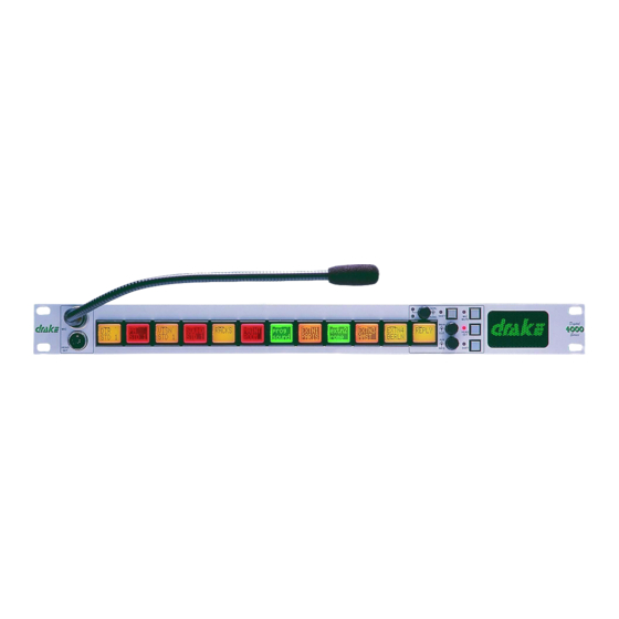
2.2.10 PD4226R/PD 4226 32-key control panel (2RU) 2.2.10.1 PD4226R Front View Microphone Socket Loudspeaker Cut Pushbutton Indicator LED Main Volume Control and Associated LED Direct Access Key (DAK) Reply Key Designation Strips Headset Socket Loudspeaker Aperture Headset Select Button and Associated Auxiliary Volume Control and LED Microphone Mute and Associated LED Figure 21 - PD4226R Front View... -
Page 52: Pd4226 Front View
2.2.10.2 PD4226 Front View Microphone Socket Main Volume Control Headset Socket Auxiliary Volume Control Direct Access Key (DAK) Loudspeaker Talk Tally LED Headset Select Pushbutton Listen Tally LED Reply Key Designation Strip Loudspeaker Cut Pushbutton Microphone Mute Pushbutton Figure 22 - PD4226 Front View Technical Manual Issue 2.1 4000 Digital Series... -
Page 53: Pd4226 Rear View
2.2.10.3 PD4226 Rear View Earth Connection Matrix Comms Connector (BNC) (Optional) DC Power Connector (DIN) Extension Panel Connector Control I/O (Optional) Matrix Comms Connector (RJ45) Audio I/O (Optional) 2.2.10.4 PD4226R/PD4226 Components 4226 CONTROL PANEL PDE 4535 PROCESSOR CARD PDE 4552 SWITCH CARD PDE 4537 AUDIO/CONTROL I/O... - Page 54 Technical Manual Issue 2.1 4000 Digital Series Page 30 STA0381...
-
Page 55: Pd4221 Lcd Key Panel (2Ru)
2.2.11 PD4221 LCD Key Panel (2RU) 2.2.11.1 PD4221 Front View Microphone Socket Soft Pushbutton Level Control Auxiliary Volume Control Shift Pushbutton Main Volume Control Microphone Mute Pushbutton Reply Key Loudspeaker Direct Access Key (DAK) Headset Select Pushbutton Headset Socket Figure 23 - PD4221 Front View NOTE: Microphone is shown here for illustrative purposes only. -
Page 56: Pd4221 Components
2.2.11.3 PD4221 Components 4221 CONTROL PANEL PDE 4535 PROCESSOR CARD PDE 4530/4532/4533 LCD SWITCH/POT CARDS PDE 4537 AUDIO/CONTROL I/O OPTIONS CARD PDE 4536 COAX/FIBRE OPTIC OPTIONS CARD Mechanical construction and wiring are shown in the associated drawings. Technical Manual Issue 2.1 4000 Digital Series Page 32 STA0381... -
Page 57: Pd4222R/Pd4222 Lcd Key Panel And Rotary Encoder (2Ru)
2.2.12 PD4222R/PD4222 LCD Key Panel and Rotary Encoder (2RU) 2.2.12.1 PD4222R Front View Microphone Socket Main Volume Control Microphone Mute Pushbutton Reply Key Shift Pushbutton Direct Access Key (DAK) Crosspoint Level Control Soft Pushbutton Loudspeaker Headset Select Pushbutton Auxiliary Volume Control Headset Socket Loudspeaker Cut Pushbutton Figure 25 - PD4222R Front View... -
Page 58: Pd4222 Front View
2.2.12.2 PD4222 Front View Microphone Socket Soft Pushbutton Level Control Auxiliary Volume Control Shift Pushbutton Main Volume Control Microphone Mute Pushbutton Reply Key Loudspeaker Direct Access Key (DAK) Headset Select Pushbutton Headset Socket Figure 26 - PD4222 Front View NOTE: Microphone is shown here for illustrative purposes only. Contact Vitec Group Communications for details of suitable products. -
Page 59: Pd4222R/Pd4222 Components
2.2.12.4 PD4222R/PD4222 Components 4222 CONTROL PANEL PDE 4535 PROCESSOR CARD PDE 4530/4532/4533 LCD SWITCH/POT CARDS PDE 4537 AUDIO/CONTROL I/O OPTIONS CARD PDE 4536 COAX/FIBRE OPTIC OPTIONS CARD Mechanical construction and wiring are shown in the associated drawings. 4000 Digital Series Issue 2.1 Technical Manual STA0381... -
Page 60: Pd4222Sr/Pd4222S Supervisor Key Panel
2.2.13 PD4222SR/PD4222S Supervisor Key Panel 2.2.13.1 PD4222SR Front View Microphone Socket Main Volume Control Microphone Mute Pushbutton Reply Key Shift Pushbutton Direct Access Key (DAK) Level Control Soft Pushbutton Loudspeaker Headset Select Pushbutton Auxiliary Volume Control Headset Socket Loudspeaker Cut Pushbutton Figure 28 - PD4222SR Front View Technical Manual Issue 2.1... -
Page 61: Pd4222S Front View
2.2.13.2 PD4222S Front View Microphone Socket Soft Pushbutton Level Control Auxiliary Volume Control Shift Pushbutton Main Volume Control Microphone Mute Pushbutton Reply Key Loudspeaker Direct Access Key (DAK) Headset Select Pushbutton Headset Socket Figure 29 - PD4222S Front View 2.2.13.3 PD4222SR/PD4222S Rear View Earth Connection Matrix Comms Connector (BNC) (Optional) DC Power Connector (DIN) -
Page 62: Pd4222Sr/Pd4222S Panel Description
2.2.13.4 PD4222SR/PD4222S Panel Description A PD4222SR/PD4222S Key Panel, when in Supervisor Mode, can mimic and control any 'target' panel in the local system. This involves remote actioning of key presses and rotary encoder changes, and displaying a mimic of the target panel's display. Whilst in Supervisor Mode all key presses and rotary encoder changes are processed at the target panel. -
Page 63: Pd4232Rbl Lcd Key Panel And Rotary Encoder (3Ru)
2.2.14 PD4232RBL LCD Key Panel and Rotary Encoder (3RU) 2.2.14.1 PD4232RBL Front View Microphone Socket Main Volume Indicator LEDs Level Control Main Volume Control Direct Access Key (DAK) Scribble Strip Indicator LED Soft Pushbutton Loudspeaker Headset Select Pushbutton Auxiliary Volume Control Shift Pushbutton Auxiliary Volume Indicator LEDs Microphone Mute Pushbutton... -
Page 64: Pd4232Rbl Rear View
2.2.14.2 PD4232RBL Rear View Earth Connection Matrix Comms Connector (BNC) (Optional) DC Power Connector (DIN) Extension Panel Connector Control I/O (Optional) Matrix Comms Connector (RJ45) Figure 32 - PD4232RBL Rear View Technical Manual Issue 2.1 4000 Digital Series Page 40 STA0381... -
Page 65: Pd4232Rbl Components
2.2.14.3 PD4232RBL Components 4232 CONTROL PANEL PDE 4535 PROCESSOR CARD PDE 45104 FRONT PANEL CARD PDE 4537 AUDIO/CONTROL I/O OPTIONS CARD PDE 4536B COAX OPTIONS CARD OR PDE 45103 CLEARCOM ISOLATION BOARD 4000 Digital Series Issue 2.1 Technical Manual STA0381 Page 41... -
Page 66: Pd4294R/Pd4294 - Desktop Control Panel
2.2.15 PD4294R/PD4294 - Desktop Control Panel 2.2.15.1 PD4294R Front View Microphone Socket Loudspeaker Headset Socket Shift Pushbutton Direct Access Key (DAK) Info Pushbutton Talk Tally LED Soft Pushbutton Listen Tally LED Call Reject Pushbutton Alphanumeric LCD Display Reply Key Headset Select Pushbutton Level Control Pushbutton Microphone Mute Pushbutton Loudspeaker Cut Pushbutton... -
Page 67: Pd4294 Front View
2.2.15.2 PD4294 Front View 18 19 Microphone Socket Loudspeaker Headset Socket Shift Pushbutton Direct Access Key (DAK) Info Pushbutton Talk Tally LED Soft Pushbutton Listen Tally LED Call Reject Pushbutton Alphanumeric LCD Display Reply Key Headset Select Pushbutton Level Control Pushbutton Microphone Mute Pushbutton Loudspeaker Cut Pushbutton Main Volume Control... -
Page 68: Pd4294R/Pd4294 Rear View
2.2.15.3 PD4294R/PD4294 Rear View DC Connector Control I/O (Optional) Audio I/O (Optional) Matrix Comms Connector Figure 35 - PD4294R/PD4294 Rear View 2.2.15.4 PD4294R/PD4294 Components 4294 DESKTOP CONTROL PANEL PDE 4538 PANEL ELECTRONICS CARD PDE 4566 DISPLAY SWITCH CARD Positions and wiring of optional cards are shown on the Assembly Drawing PDE 4534 RJ45 CARD... - Page 69 Mechanical construction and wiring are shown in the associated drawings. 4000 Digital Series Issue 2.1 Technical Manual STA0381 Page 45...
-
Page 70: Pd4295Mci Lcd Desktop Panel
2.2.16 PD4295MCI LCD Desktop Panel Microphone Socket Headset Select Pushbutton Headset Socket Soft Pushbutton Crosspoint Level Control Auxiliary Volume Control Shift Pushbutton Reply Key Main Volume Control Loudspeaker Microphone Mute Pushbutton Direct Access Key (DAK) Figure 36 - PD4295MCI Front View Technical Manual Issue 2.1 4000 Digital Series... -
Page 71: Pd4295Mci Components
2.2.16.1 PD4295MCI Components 4295MCI CONTROL PANEL PDE 4535 PROCESSOR CARD PDE 4530/4531/4533 LCD SWITCH/POT CARDS PDE 4537 AUDIO/CONTROL I/O OPTIONS CARD PDE 4536 COAX/FIBRE OPTIC OPTIONS CARD 4000 Digital Series Issue 2.1 Technical Manual STA0381 Page 47... -
Page 72: Pd4296Mci Lcd Desktop Panel
2.2.17 PD4296MCI LCD Desktop Panel Microphone Socket Headset Select Pushbutton XLR5 Headset Socket Soft Pushbutton Crosspoint Level Control Auxiliary Volume Control Shift Pushbutton Reply Key Main Volume Control Loudspeaker Microphone Mute Pushbutton Direct Access Key (DAK) Figure 37 - PD4296MCI Front View Technical Manual Issue 2.1 4000 Digital Series... -
Page 73: Pd4296Mci Components
2.2.17.1 PD4296MCI Components 4296MCI CONTROL PANEL PDE 4535 PROCESSOR CARD PDE 4530/4531/4533 LCD SWITCH/POT CARD PDE 4537 AUDIO/CONTROL I/O OPTIONS CARD PDE 4536 COAX/FIBRE OPTIC OPTIONS CARD 4000 Digital Series Issue 2.1 Technical Manual STA0381 Page 49... - Page 74 Technical Manual Issue 2.1 4000 Digital Series Page 50 STA0381...
-
Page 75: Extension Panels
2.3 Extension Panels 2.3.1 PD4203R/PD4203 - Level Control Panel (1RU) 2.3.1.1 PD4203R Front View Level Adjustment Control Designation Strip Figure 38 - PD4203R Front View 2.3.1.2 PD4203 Front View Level Adjustment Control Designation Strip Figure 39 - PD4203 Rear View 2.3.1.3 PD4203R/PD4203 Rear View Extension Connector Figure 40 - PD4203R/PD4203 Rear View... -
Page 76: Pd4203R/Pd4203 Control Panel Description
2.3.1.4 PD4203R/PD4203 Control Panel Description The 4203 1RU Level Control Extension Panel has 20 rotary level controls which allow individual crosspoint levels in the Matrix to be varied. The Extension Panel can be connected to either a standard 4000 Control Panel or a 4000 Router Panel. When a single panel is connected with a 4000 Control Panel, the rotary controls can be arranged to correspond to the upper or lower row of DAKs. -
Page 77: Pd4206R/Pd4206 - 20 Key Extension Panel (1Ru)
2.3.2 PD4206R/PD4206 - 20 Key Extension Panel (1RU) 2.3.2.1 PD4206R Front View Indicator LED Designation Strip Direct Access Key (DAK) Figure 41 - PD4206R Front View 2.3.2.2 PD4206 Front View Direct Access Key (DAK) Listen Tally LED Talk Tally LED Designation Strip Figure 42 - PD4206 Front View 4000 Digital Series... -
Page 78: Pd4206R/Pd4206 Rear View
2.3.2.3 PD4206R/PD4206 Rear View Extension Connector Figure 43 - PD4206R/PD4206 Rear view 2.3.2.4 PD4206R/PD4206 Extension Panel Description The PD4206R/PD4206 1RU Extension Panels provide 4000 Control Panels with up to 20 additional centrally assigned (via CMAPSi) DAKs. 2.3.2.5 PD4206R/PD4206 Components 4206R/4206 20 KEY EXTENSION PANEL PDE 4558 EXTENSION PANEL CARD... -
Page 79: Pd4230R Half Width Lcd Extension Panel (1Ru)
2.3.3 PD4230R Half Width LCD Extension Panel (1RU) Shift mode LED Reply Key Crosspoint Level Control Direct Access Key (DAK) Talk Tally LED Shift Pushbutton Listen Tally LED Figure 44 - PD4230R Front View Extension Panel Connector (RJ45) DC Power Connector (DIN) Matrix Comms Connector (RJ45) Figure 45 - PD4230R Rear View 4000 Digital Series... -
Page 80: Pd4230Rv Half Width Vertical Lcd Control Panel (1Ru)
2.3.4 PD4230RV Half Width Vertical LCD Control Panel (1RU) Shift mode LED Reply Key Crosspoint Level Control Direct Access Key (DAK) Talk Tally LED Shift Pushbutton Listen Tally LED Figure 46 - PD4230R Front View Technical Manual Issue 2.1 4000 Digital Series Page 56 STA0381... -
Page 81: Pd4231R Half Width Lcd Control Panel (1Ru)
2.3.5 PD4231R Half Width LCD Control Panel (1RU) Main Volume Control Direct Access Key (DAK) Listen Tally LED Shift LED Talk Tally LED Shift Pushbutton Crosspoint Level Control Figure 47 - PD4231R Front View DC Power Connector (DIN) Headset Connector (DIN) Audio I/O (optional) Matrix Comms Connector (RJ45) Figure 48 - PD4231R Rear View... - Page 82 Technical Manual Issue 2.1 4000 Digital Series Page 58 STA0381...
-
Page 83: Sub Assembly Pcbs
3 Sub Assembly PCBs 3.1 PDE 4505 Key extension card Figure 49 - PDE4505 Key Extension card This card contains the 20 keys and associated LEDs for the PD4206 key extension panel. The keys and LEDs are arranged in a matrix of rows and columns to reduce interconnection. 3.2 PDE 4530 LCD switch driver card Figure 50 - PDE4530 LCD Switch Driver Card This card contains the necessary circuitry to interface the PDE4531/4532/4533 cards to the PDE4535... -
Page 84: Pde 4532 2U Lcd Key Card
This card contains the 12 LCD keys for the PD4211 panel and In its fully fitted form (/LVL) it also contains the encoders and associated LEDs for the PD4212 panel. 3.4 PDE 4532 2U LCD Key Card Figure 52 - PDE4532 LCD Key Card This card contains the 12 LCD keys for the PD4211 panel and In its fully fitted form (/LVL) it also contains the encoders and associated LEDs for the PD4212 panel. -
Page 85: Pde 4535 Panel Electronics Card
3.7 PDE 4535 Panel Electronics Card Figure 55 - PDE4535 Panel Electronics Card The PDE4535 is the panel processor card for non-19" 4000 series II panels. It provides microphone amplifier/loudspeaker amplifier/power supply/processor/memory and control interfaces. 3.7.1 PDE4535 Circuit description U8 is the microphone amplifier 30 to 60dBs of gain, which is software selectable by U6. Up to two microphones can be connected to CON3 &... -
Page 86: Pde 4536 Coax/Fibre Options Card
3.8 PDE 4536 Coax/Fibre Options Card The PDE4536 is the coax/fibre options board for the 4000 series II panel range. It is plug compatible with both the PDE4535 & PDE4538 panel processor cards. The PDE 4536 has two build versions depending on the type of interconnection required. The PDE4536 allows 75W coax interconnection between the control panel and the matrix, whilst the PDE4536MMST allows multi-mode fibre interconnection on ST connectors. -
Page 87: Pde 4537 Panel Audio/Gpi Options Card
75R BNC Tx Control & Audio data Tx Audio data Audio in L Audio in R Clock CODEC Audio out L Receiver Rx Audio data Audio out R 3.9 PDE 4537 Panel Audio/GPI Options Card Figure 57 - PDE4537 Panel Audio/GPI Options Card This card handles two balanced audio mix inputs and two balanced audio send outputs from the panel it is fitted to. -
Page 88: Pde 4538 Panel Electronics Card
3.10 PDE 4538 Panel Electronics Card The PDE4538 is the panel processor card for non-19" 4000 series II panels. It provides microphone amplifier/loudspeaker amplifier/power supply/processor/memory and control interfaces. U4 U22 CON11 CON13 CON17 CON10 CON7 CON8 LK10 Figure 58 - PDE4538 Panel Electronics Card 3.10.1 PDE4538 Circuit description U8 is the microphone amplifier 30 to 60dBs of gain, which is software selectable by U6. -
Page 89: Pde 4551 Key/Lcd Display Card
U3 provides +12V for the analogue electronics and TR1/U4/U29 provide a -7.5V rail. U17 is the 68000 control CPU, which runs bootstrap code, fitted at U18 and non-volatile downloaded code from the matrix stored in U22. U19 is a 1Mbit static ram for all volatile data. U25 is a dual channel UART, one channel for serial communication with the matrix and the other a spare. -
Page 90: Pde 4552 Key Card
3.12 PDE 4552 Key Card Figure 60 - PDE4552 Key Card This card contains the 35 keys , and associated LEDs for the PD4226 panel. The keys and LEDs are arranged in a matrix of rows and columns to reduce interconnection. U1-5 perform the decode circuitry necessary to drive these signals. -
Page 91: Pde 4556 Key/Led Display Card
3.15 PDE 4556 Key/LED Display Card Figure 62 - PDE4556 Key/LED Display card This card contains the 20 keys and associated LEDs and LED displays for the PD4217 panel. The keys and LEDs are arranged in a matrix of rows and columns to reduce interconnection. 3.16 PDE 4557 Drive Card Figure 63 - PDE4557 Drive Card This card contains the necessary circuitry to interface the PDE4556 card to the PDE4535 panel... -
Page 92: Pde 4558 Panel Electronics Card
3.17 PDE 4558 Panel Electronics Card This card contains the driving circutiry inside a PD4206 panel between the PDE4505 extension key card and the main panel. U6 & 7 are buffers for interfacing the circuitry to the main panel. U3,4,5 & 26 form the switch encoding logic which generates the necessary row and column scan lines. SW1 is a hex switch used for selecting the function of the PD4206 panel ie for panel position. -
Page 93: Digital Routing Matrix
4 Digital Routing Matrix 4.1 Racks 4.1.1 4420 4U rack PDE4629 is the backplane sub-assembly as used in the 4420 4U rack frame. It contains 7 pairs of 96 way DIN41612 connectors for rack cards and 2 off 15 way DIN41612 connectors for PD4172 power supply units. -
Page 94: Pde4641 60-Way Simm Card
4.1.3 PDE4641 60-way SIMM card Figure 64 - PDE4641 60-way SIMM Card This sub-assembly is a 60 way SIMM card which is uniquely programmed with a PROM(U1) for identification of allowed features by the PDE4642 processor card. It is fitted to the rear of PDE4629/4639 backplanes. 4.2 Front Cards The digital and control processing for the system is carried out by a number of electronic cards. -
Page 95: Figure 66 - Pde 3601A - Block Diagram
circuit and a common Output RAM. A block diagram is shown below. Note that the block diagram only illustrates one router. A sub-fitted version of this card is used in the smaller 4420 matrices. This card has one quarter of the routing capacity of the fully fitted card. -
Page 96: Pde 4621A - 16 Channel Codec Card
4.2.2 PDE 4621A - 16 Channel CODEC Card Figure 67 - PDE4621A 16 Channel CODEC Card The CODEC card is a 16-channel 16-bit analogue to digital and digital to analogue converter. Sampling rate of 42.7kHz give a bandwidth of 17kHz. A control bus provides communication with a central processor. -
Page 97: Figure 68 - Pde 4621A - Block Diagram
Figure 68 - PDE 4621A - Block Diagram 4000 Digital Series Issue 2.1 Technical Manual STA0381 Page 73... -
Page 98: Pde4631 - 16 Channel Audio Input / Output Codec Card
4.3 PDE4631 - 16 Channel Audio Input / Output CODEC Card The PDE4631 CODEC Card is a 16-channel analogue-to-digital and digital-to-analogue converter. Either the PDE4622 CODEC RCU or the PDE4628 Serial Communications RCU can be used in conjunction with this card. Each input to the card incorporates voice detection (VOX) with a threshold which can be adjusted in CMAPSi. -
Page 99: Controls And Indicators
4.3.2 Controls and Indicators Three LEDs are mounted on the leading edge of the board; they indicate satisfactory +5V, -5V and initialised status 4.3.3 Description Sampling rate of 42.7kHz give a bandwidth of 20kHz. A control bus provides communication with a central processor. -
Page 100: Pde 4606A - Panel Communications Card (Pcc)
4.3.4 PDE 4606A - Panel Communications Card (PCC) Figure 71 - PDE4604A Panel Communications Card The PCC sends audio data from each of 16 destination time-slots on the digital audio backplane to a corresponding outstation. Control data sent from the Microprocessor card is multiplexed into the data stream for each outstation. -
Page 101: Figure 72 - Pde 4606A - Block Diagram (Control)
PDE 4606A - Block Diagram (Audio) Figure 72 - PDE 4606A - Block Diagram (Control) 4000 Digital Series Issue 2.1 Technical Manual STA0381 Page 77... -
Page 102: Pde4606B - 16 Channel Panel Communications Card
4.4 PDE4606B - 16 Channel Panel Communications Card The PDE4606B Panel Communications Card sends and receives the combined digital audio and control data for each Control Panel. Figure 73 - PDE4606B 16 Channel Communications Card 4.4.1 Card Locations These cards may be located in any slot from 3 to 20 in the 4920 matrix, or any slot from 2 to 7 in the 4420 matrix. -
Page 103: Pde4644 - Digital Matrix Card
Table 3: PDE4606B LEDs -5 Volts LED on if -5V present Flashes for correct card operation. (A faster rate indicates Status increased data transfer) Initialized Matrix has recognised and initialised card. 4.4.3 PDE4644 - Digital matrix card Figure 74 - PDE4644 Digital Matrix Card PDE4644 is an optional quarter-sized PDE3601A for fitting onto a PDE4642 in the case of small systems.Refer to PDE3601A for further information. -
Page 104: Pde 4642 Microprocessor Card (Mpc)
A green LED is provided on the front of the unit to indicate that the unit power supply is operating correctly. 4.4.5 PDE 4642 Microprocessor Card (MPC) Figure 75 - PDE4642 Microprocessor Card The PDE4642 is the main processor card for 4000 series II systems. It runs on a 68360 processor at 25 MHz and contains a 64kbyte/128kbyte boot PROM, one 8Mbyte SIMM DRAM, 256kbyte of battery backed SRAM and 2 Mbytes of flash ROM. -
Page 105: Controls And Indicators
4.4.6 Controls and Indicators Five LEDs are mounted on the leading edge of the board.; they give indication of the processor status; their operation is detailed in the Installation Guide. System Reset and 'Bootstrapping' the system are also explained in the 4000 Digital Series Installation Guide. -
Page 106: Pde Rear Connector Units
4.6 PDE Rear Connector Units Rear Connector Units (RCUs) provide a flexible solution to linking the processing and data handling cards mounted in the matrix to control panels and peripheral equipment. Note that, in general, RCUs are loaded into slots corresponding to their 'front-loading' companion board; actual positions are dictated by the system 'map'. -
Page 107: Pde 4643 - Processor I/O Rcu (Rs232/Rs422)
This RCU performs the same function as the 3622 RCU, except that the audio inputs and outputs are electronically balanced. 4.6.3 PDE 4643 - Processor I/O RCU (RS232/RS422) Figure 79 - PDE4643 Processor I/O RCU The PDE4643 is the processor card rear connector unit and provides connectors for the 2 serial ports, the ethernet AUI , 10BaseT and coax connectors for synchronising the audio clock of different matrices. -
Page 108: Pde4663 - Central Processor Rcu Card
4.7 PDE4663 - Central processor RCU Card Figure 80 - PDE4663 - Central processor RCU Card The PDE4663 RCU provides connections to the RS232 (two 9-way socket D-type connector) ports available on the Microprocessor cards (PDE4662). Only one RCU is required per matrix rack. It provides three RJ45 Ethernet twisted pair connections. -
Page 109: Connector Details
• 6 - 14.2 KHz • 7 - 12.8 KHz • Link LK10. This link is factory set and should not be changed. • Link LK11. This link sets the internal/external powering of the GPI opto-isolators as defined below: • Pins 1-2 linked - opto-isolators powered internally from Vcc (not isolated) (default). -
Page 110: Table 5: Pde4663 - Gpi Outputs
Table 5: PDE4663 - GPI Outputs Description Description Number Number Relar Output 1 P Relay Output 7 P Relay Output 1 N/C Relay Output 7 N/C Relay Output 1 N/O Relay Output 7 N/O Relay Output 2 P Relay Output 8 P Relay Output 2 N/C Relay Output 8 N/C Relay Output 2 N/O... -
Page 111: Table 6: Pde4663 - Ethernet Rj45
Table 6: PDE4663 - Ethernet RJ45 Description Number Data Transmit (TD+) Data Transmit (TD-) Data receive RD+) Data Receive (RD-) Table 7: PDE4663 - Serial 1 and 2 Description Number Data Receive (Rx) Data Transmit (Tx) Screen 4000 Digital Series Issue 2.1 Technical Manual STA0381... -
Page 112: Pde4663B - Central Processor Rcu Card
4.8 PDE4663B - Central Processor RCU Card Figure 81 - PDE4663B RCU Card The PDE4663B RCU card is functionally identical to the PDE4663 RCU card other than it now includes the dongle that was previously fitted externally. The PDE4663B RCU provides connections to the RS232 (two 9-way socket D-type connector) ports available on the Microprocessor cards (PDE4662). -
Page 113: Card Location
The card also provides dual clock circuits with auto-fail detected and changeover if this happens. LEDs D3 and D5 show which clock is the master. 4.8.1 Card location One of these cards must be located in RCU slot 2 in the 4920 matrix, or RCU slot 1 in the 4420 matrix. 4.8.2 Links Before fitting this card the links should be checked to ensure that they are correctly set for the application. -
Page 114: Table 9: Pde4663B - Gpi Outputs
Table 8: PDE4663B - GPI Inputs Description Description Number Number GPI Input 11 GPI Input 12 N.C. 7-16 N.C. 26-35 Isolated Inputs (requires external +7 Tech 0 Volts Volts to +24 Volts applied) Isolated Inputs (requires external +7 Tech 0 Volts Volts to +24 Volts applied) Common 24V Return Table 9: PDE4663B - GPI Outputs... -
Page 115: Table 10: Pde4663B - Ethernet Rj45
Table 9: PDE4663B - GPI Outputs Description Description Number Number Relay Output 4 P Relay Output 10 P Relay Output 4 N/C Relay Output 10 N/C Relay Output 4 N/O Relay Output 10 N/O Relay Output 5 P Relay Output 11 P Relay Output 5 N/C Relay Output 11 N/C Relay Output 5 N/O... -
Page 116: Pde4645 - Optional Gpi Card
Table 11: PDE4663B - Serial 1 and 2 Description Number Data Receive (Rx) Data Transmit (Tx) Screen 4.8.4 PDE4645 - Optional GPI card PDE4645 is an optional GPI card for fitting onto a PDE4643 in the case of small systems. It is in effect a reduced capacity PDE4619 containing 12 opto-isolated inputs and 12 relays. -
Page 117: Card Location
The SCRCU requires two EPROM devices. Before fitting this card ensure that the EPROMS are present and verify that the version of firmware is correct for the application. Figure 82 - PDE 4628 - 16 Channel Serial Communications RCU 4.8.5.1 Card Location These cards may be located in any RCU slot from 3 to 20 in the 4920 matrix, or any RCU slot from 2 to 7 in the 4420 matrix. - Page 118 Table 12: PDE 4628 Self Tests Action LED Display Indication Code Checksum Test Appears for 0.5 seconds Workspace RAM Test Appears for 1 second Dual Port RAM Test Appears for 0.25 seconds Initialisation Test Appears for 0.25 seconds Normal Operation Flashes at 2Hz to indicate processor is running Message Received PDE4628 has received a message on a communica-...
-
Page 119: Data And Audio Connections
Table 12: PDE 4628 Self Tests Action LED Display Indication Channel Status Indicates the channel status - as shown below Channel Channel Each LED is able to indicate the status of the channel that it represents. The various conditions are shown below. -
Page 120: Pde 4619 - General Purpose Interface (Gpi) Rcu
Table 13: PDE 4628 RS422 RJ45 Pinout RJ45 Connector Pin Number Description (Matrix End) Data Receive (Rx+) Data Receive (Rx-) Audio Input (+) Audio Output (+) Audio Output (-) Audio Input (-) Data Transmit (Tx+) Data Transmit (Tx-) 4.8.6 PDE 4619 - General Purpose Interface (GPI) RCU The GPI card provides 32 open-collector outputs and 32 15V CMOS inputs for DC input and output control of external equipment from the 4000 Digital Series. -
Page 121: Figure 84 - Pde4619 General Purpose Interface (Gpi) Rcu
Figure 84 - PDE4619 General Purpose Interface (GPI) RCU Figure 85 - PDE 4619 - Block Diagram 4000 Digital Series Issue 2.1 Technical Manual STA0381 Page 97... -
Page 122: Mains Panel (4U And 9U Racks)
4.8.7 Mains Panel (4U and 9U Racks) The Mains Panel on the 9U rack is a fixed panel on the right-hand side at the rear of the unit, and on the left-hand side for the 4U rack. Details of the connector pin outs are given in the 4000 Digital Series Installation Guide. -
Page 123: Supply Protection
Table 14: Matrix Card Power Requirements PDE4606 Panel Communications Card +5V @ 2.0A; -5V @ 0.1A PDE4621 16 Channel CODEC Card +5V @ 1.0A; -5V @ 0.05A, ±18V @ 0.08A PDE4609 Telephone Control Interface Card +5V @ 0.1A PDE4619 GPI RCU +5V @ 1.0A PDE3628 Serial Communications RCU... - Page 124 Technical Manual Issue 2.1 4000 Digital Series Page 100 STA0381...
-
Page 125: Specifications
5 Specifications Frame Size 9RU - 4920: 482mm (19 inches) wide 400mm (9RU) high 500mm (20 inches) deep 4U - 4420: 482mm (19 inches) wide 168mm (4RU) high 485mm (19.5 inches) deep Weight: 20 to 25kg Power Requirements: 90V to 250V, 50/60Hz, 300W max Frequency Response: 30Hz - 17kHz ±3dB Crosstalk (adjacent channel) - Page 126 Output Balance <-30dBu Linearity ±1dB GPI Inputs: 37 way D-type, Opto-isolated GPI Outputs: 37 way D-type, Isolated relay Open collector driver Control Inputs/Outputs: 25 way D-type RS232, 9 way D-type RS422, Thinnet / AUI Ethernet® AC power Inputs/Outputs 4920: 2x IEC AC input, 9 way D-type Alarm o/p 4420: 2x IEC AC input...
- Page 127 INDEX Numerics 2RU LCD Key Panel GPI block diagram ........31 .......... 97 4000 Digital Series ..........2 4000 Power Arrangements ......98 4016 cabling ............15 Headset Select Pushbutton and Associated 4420 4U rack ............. 69 ............19 4920 9U rack .............
- Page 128 PD4206R/PD4206 - 20 Key Extension PD4225R Front View ........24 Panel (1RU) PD4225R/PD4225 Rear View ............53 ..... 26 PD4206R/PD4206 Components PD4225R/PD4225 Rear view ....54 ...... 26 PD4206R/PD4206 Extension Panel PD4225R/PD4225 Router Control Panel Description (2RU) ............54 ..............24 PD4206R/PD4206 Mechanical Construction PD4226 Front View ........
- Page 129 PDE 4566 Key/LCD Display Card PDE4631 16 Channel CODEC Card ....68 ..74 PDE 4606A - Panel Communications Card PDE4631 Card Block Diagram ....75 (PCC) PDE4641 60-way SIMM card ..............76 ...... 70 PDE 4619 - General Purpose Interface PDE4642 Microprocessor Card ....
- Page 130 Technical Manual Issue 2.1 4000 Digital Series Page iv STA0381...
- Page 131 UHF wireless intercom systems have a limited warranty of three years. • All other Clear-Com and Drake brand systems and products, including beltpacks, have a limited warranty of two years. The warranty starts at the time of the product’s original purchase. The warranty start date for contracts which include installation and commissioning will commence from the date of the Site Acceptance Test (SAT), or three months from purchase, whichever is sooner.
- Page 132 24 x 7 customer support in addition to the warranty immediately upon purchase of the warranty extension. Note: Clear-Com does not offer warranty extensions on UHF wireless intercom systems, or on any product with a 1-year or 90-day warranty.
- Page 133 This warranty does not include defects arising from installation (when not performed by VGC), lightning, power outages and fluctuations, air conditioning failure, improper integration with non-approved components, defects or failures of customer furnished components resulting in damage to VGC provided product.
- Page 134 4000 Digital Series Issue 2.1 Technical Manual STA0381 Page iv...
Need help?
Do you have a question about the 4000 II Series and is the answer not in the manual?
Questions and answers