
Related Manuals for ODA OPX-93D


Summary of Contents for ODA OPX-93D
- Page 1 Programmable DC Power Supply OPX-93D User Manual Manual Part NO. 018OPX-93D-2.0...
- Page 2 ODA shall not be liable for errors or for incidental or be liable for errors or for incidental or consequential damages in connection with the furnishing, use, or performance of this document or of any information contained herein.
- Page 3 Failure to comply with these precautions or with specific warnings or instructions elsewhere in this manual violates safety standards of design, manufacture, and intended use of the instrument. ODA Technologies assumes no liability for the customer's failure to comply with these requirements. General...
- Page 4 Safety Symbol Direct current Alternating current Both direct and alternating current Three phase alternating current Earth (ground) terminal Protective earth ground terminal. Frame or chassis terminal Terminal is at earth potential. Neutral conductor on Line conductor on permanently installed permanently installed equipment. equipment Standby supply.
-
Page 5: Table Of Contents
CONTENTS 1. Product Outline -------------------------------------------------- 1-1. Product Characteristics ---------------------------------- General Functional Characteristics Remote Interface Characteristics C lib Calibration Characteristics Factory Function Characteristics Self Test Characteristics 1-2. Accessories ----------------------------- Accessories 1-3. Product Inspection --------------------------------------------- Equipment Check Biographic Check hi Ch 1-4. Working Condition --------------------------------------------- 1-5. - Page 6 3-4. Programming Over Voltage Protection(OVP) ------------------- 3-5. Programming Over Current Protection(OCP) ------------------- 3-6. Programming Under Voltage Limit(UVL) ------------------- 3-7. Programming Over Voltage Limit(OVL) ------------------- 3-8. Programming Under Current Limit(UCL) ------------------- 3-9. Programming Over Current Limit(OCL) ------------------- 3 10 KEY LOCK 3-10.
- Page 7 5. FACTORY ------------------------------------------------------- 5-1. Characteristics -------------------------------------------------- 5-2. FACTORY KEY Structure -------------------------------- 5-3. USER-MEM CLEAR -------------------------------------------- USER-MEM CLEAR Operation 5-4. LAST STATE ----------------------------------------------- LAS S A LAST STATE Operation 5-5. AUTO CURSOR MV --------------------------------------------- AUTO CURSOR MV Operation 5-6. AUTO KEY LOCK ----------------------------------------------- AUTO KEY LOCK Operation 5-7.
- Page 8 7. Error Messages ------------------------------------------------- 7-1. Operational Error ------------------------------------------- 7-2. Hardware Error ------------------------------------------------- 7-3. Remote Calibration Error --------------------------------- 68 7-4. Calibration Error ----------------------------------------------- 7-5. Fixed Memory Check Error ----------------------------- 7-6. Interface Commands Error --------------------------------- 8. Specifications ------------------------------------------------- 9. Warnings 9. Warnings ------------------------------------------------------- - 5 -...
-
Page 9: Product Outline
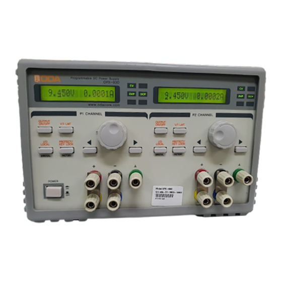
1. Product Outline 1-1. Product Characteristics OPX-93D is 0~9V / 0~3A Dual Output Programmable Direct Current Supply Equipment. It is optimized and designed for mobile testing equipment with 1/2-19inch 3U height. It supports RS-232C and GPIB Communication follow as SCPI (Standard Commands for Programmable Instruments). -
Page 10: Accessories
1-2. Accessories Accessories ▌One 1.5M Power Cord ▌One Spare Fuse ▌One User's Manual 1-3. Product Inspection Please check below features after opening box. If a problem occurs please ask service center or main office about A/S service. Please pack the product fully with box package. Also, check our homepage Q&A for further information. -
Page 11: Working Condition
1-4. Working Condition This product is appropriate in below circumstances. ▌Ambient Temperature : 0 ∼ 40℃ ▌Humidity : less than 80% ▌Altitude : less than 2000m ▌ ▌Place where has no vibration ▌Place not be effected by magnetic field 1-5. Check Before Input Power Check Power Cord ▌Supplied power cord is 3-Wire Ground Type, If you like to use separate power cord, please use Ground type. -
Page 12: Check After Input Power
▌"ODA Technologies" will be displayed. " ill b di ▌"OPX-93D Ver x.x" will be displayed. ▌Front OVP,OCP,RMT,ERR Lamp will be lighted clockwise and lighted out CV Lamp light-off/CC Lamp light-on/CV Lamp light-on/CC Lamp light-on & off. ▌While above features are displaying, a reset will be done by fixed memory. -
Page 13: Product Installation
1-7. Product Installation Cooling ▌The product is guaranteed in 0℃ ~ 40℃ condition, so please consider the place to use. In area 40℃ ~ 55℃, reduce output current 0~70%. When it is installed in Rack, please consider about ventilation. <Diagram 1-3 Bottom view> Bench Operation ▌There should be spare spaces on products side front rear for ventilation ▌There should be spare spaces on products side, front, rear for ventilation. -
Page 14: Front Panel, Rear Panel Structure & Function
2. Front Panel, Rear Panel Structure & Function Channel1(P1) 16Char Type LCD Display Left Displace Cursor & Menu change Key Channel2(P2) 16Char Type LCD Display 14 Right Displace Cursor & Menu change Key CV Mode Lamp 15 Variable Encoder CC Mode Lamp 16 Positive Output OVP Set-up Condition Lamp 17 Negative Output... - Page 15 1. Channel 1(P1) 16Char Type LCD Display Menu which shows Channel 1 Voltage/Current value, Option, Various Menu. 2. Channel 2(P2) 16Char Type LCD Display Menu which shows Channel 2 Voltage/Current value, Option, Various Menu. From the sight of front side, Channel 1 and Channel 2 are bisymmetry, independent control method.
- Page 16 13. Left Displace Cursor & Menu change Key Change Voltage/Current Range, Cursor will move Left. In Menu Mode, it can be used to change Menu left side. 14. Right Displace Cursor & Menu change Key Change Voltage/Current Range, Cursor will move Right. In Menu Mode, it can be used to change Menu right side.
-
Page 17: Front Panel Voltage Current Setting
2-1. Front panel Voltage Current Setting Use Below Method to Set-up limit value. 1. Check whether "**OUTPUT OFF**" is displayed after Power ON. 2. In front sight of view, left side is channel 1(P1), right side is channel 2 (P2). 3. -
Page 18: Rear Panel Structure
2-2. Rear Panel Structure Model Name & Serial Number Channel 2(P2) GPIB Port Channel 1(P1) RS232C Port AC Input Inlet Channel 1(P1) GPIB Port Ventilating Opening Channel 2(P2) RS232C Port 1. Model Name & Serial Number Sticker which involves product model name & Electronic capacity, fuse capacity, serial number. Sticker which involves product model name &... -
Page 19: Operating Front Panel
3. Operating Front panel When there is no event for 10 seconds or by pressing I/O LOCAL, PROTECT Key, The menu will move in to Local Mode Automatically. Menu select & check key provides simple and convenience to users. Overview 1. -
Page 20: Constant Voltage Operation(Cv)
3-1. Constant Voltage Operation(CV) Constant Voltage output Mode, Follow the sequence below. (When Last State Mode is disabled.) ▌Power Switch ON Check "**OUTPUT OFF**" Mode when the power is ON. ▌Connect load to output terminal. ▌Press V/I LMT Key to set-up the Limit value. ▌To set-up voltage, use cursor key. -
Page 21: Constant Current Operation(Cc)
3-2. Constant Current Operation(CC) Constant Current output Mode, Follow the sequence below. (When Last State Mode is disabled.) ▌Power Switch ON Check "**OUTPUT OFF**" Mode when the power is ON. ▌Connect load to output terminal ▌Connect load to output terminal. ▌Press V/I LMT Key to set-up the Limit value. -
Page 22: Remote Voltage Sensing
3-3. Remote Voltage Sensing Regulation occurs when the load is connected with power supply output terminal, in connection lead line. Therefore, to provide accurate power, Remote Voltage Sensing can be used. Please follow the steps below to use V-Sensing. CV R CV Regulation l ti Read Reference about Specification's Voltage Load Regulation Characteristics Below :... -
Page 23: Stability
Stability Using V-sensing with long load line and high-capacity combinated could cause problems because it operates as a part of voltage feedback root as filter. This might cause problems in stability with output because of power supplies fast response time. This unstable root will be feedback and make another problems to power supply. -
Page 24: Programming Over Voltage Protection(Ovp)
3-4. Programming Over Voltage Protection(OVP) Function that protects by shutting off output voltage when the voltage is higher than OVP Level. Disable OVP function in Factory Mode. Read OVP Level Set-up Below. OVP Level Value below can be different. ▌Power Switch ON Check "**OUTPUT OFF**"... - Page 25 Third There can be a trip when load source. When Battery charge & discharge occurs, its level can be higher than setting value. Below diagram shows how to prevent it with inserting diode with right current capacity. < Diagram 3-2 > Fourth If it is difficult to manage Tripping, There is a way to Turn OVP Function OFF in force.
-
Page 26: Programming Over Current Protection(Ocp)
3-5. Programming Over Current Protection(OCP) If output current is higher than OCP Level, this function shut off the output current to protect load from power supply. It is OCP Level Set-up & ON,OFF set-up below : OCP Level Value below can be different. ▌Power Switch ON Check "**OUTPUT OFF**"... - Page 27 Third There can be a trip when load source. When Battery charge & discharge occurs, its level can be higher than setting value. Above diagram shows how to prevent it with inserting diode with right current capacity. Fourth If it is difficult to manage Tripping, There is a way to Turn OCP Function OFF in force. To turn it OFF, go to Factory Mode, and "Disable"...
-
Page 28: Programming Under Voltage Limit(Uvl)
3-6. Programming Under Voltage Limit(UVL) Users are able to change 0V to maximum voltage. However if user input voltage in UVL, from this point users are able to change UVL voltage to maximum voltage. UVL Level Value below can be different. ▌Power Switch ON Check "**OUTPUT OFF**"... -
Page 29: Programming Over Voltage Limit(Ovl)
3-7. Programming Over Voltage Limit(OVL) Users are able to change 0V to maximum voltage. However if user input voltage in OVL, from this point users are able to change 0V to UVL voltage. OVL Level Value below can be different. ▌Power Switch ON Check "**OUTPUT OFF**"... -
Page 30: Programming Under Current Limit(Ucl)
3-8. Programming Under Current Limit(UCL) Users are able to change 0A to maximum current using encoder switch. However, when users input UCL to the current, from this point, UCL current to maximum current are able to change. UCL Level Value below can be different. ▌Power Switch ON Check whether "**OUTPUT OFF**"... -
Page 31: Programming Over Current Limit(Ocl)
3-9. Programming Over Current Limit(OCL) It is possible to variety 0A to maximum current using encoder switch. However if user input from this point, it can only variety 0A to OCL current set-up value. OCL Level Value below can be different. ▌Power Switch ON Check whether "**OUTPUT OFF**"... -
Page 32: Key Lock
3-10. KEY LOCK Function which lock and unlock Front Panel keys. It prevents changing set-up value or encoder variable by users mistake. ▌Power Switch ON Check whether "**OUTPUT OFF**" Mode is displayed after Power ON. ▌Press KEY LOCK Key long enough to prevent other keys in Front panel. "**KEY LOCK**"... -
Page 33: Io/Local
3-11. IO/Local This is Key to use Remote Interface, setting RS-232C, GPIB. To use Remote Interface, a setting must be done first. When the product is released, it is selected in GPIB Protocol, Channel 1(P) Address Number 5, Channel 2 (P2) Address is Number 6. Communication setting can be set-up only in Front Panel. -
Page 34: Gpib Installation Set-Up
GPIB Installation Set-Up GPIB Connecter is standard 24-pin, and located at Rear Panel. < Diagram 3-3 > ▌GPIB PC I t f ▌GPIB PC Interface Installation t ll ti Cable line should be shield line, and should not be longer than 2M. Also, distance between the equipments should not longer than 20M total. -
Page 35: Rs232C Set-Up
RS232C Set-up Follow sequence below to set-up RS232C. ▌Power Switch ON Check whether "**OUTPUT OFF**" Mode is displayed after Power On. ▌Press I/O LOCAL Key to set-up RS232C. LCD Display Description I/O> 2.RS232C can be different by condition. ▌In accordance of previous condition, RS-232C or GPIB will be displayed. If it is not "2.RS232C", press cursor key to display "I/O>... - Page 36 ▌To connect product and Remote device, Female type of standard Cross cable required. It is explanation about Female type standard cross table wire diagram. Read reference"1-2. Accessories & Product Option Option" to select wire distances. < Diagram 3-6 > < Diagram 3-6 > ▌It is convenient when user use adopt cable separately while providing DB25Pin.
-
Page 37: Lmt Display
3-12. V/I & LMT DISPLAY Limit Display function allows users to check set-up voltage and current. Also, user could select locations of cursor for voltage and current. LMT DISPLAY Function Check Voltage/Current set-up value. ▌P ▌Power Switch ON S it h ON Check whether "**OUTPUT OFF**"... -
Page 38: Output On/Off
3-13. Output ON/OFF Function that supplies or shut-off sources from output terminal. Therefore, user could shut-off not removing the load. Follow the sequence below : ▌Power Switch ON Check whether "**OUTPUT OFF**" is displayed after input Power. ▌It is shut-off setting. To allow print source, press OUTPUT ON/OFF Key. ▌To shut-off sources, press OUTPUT ON/OFF once more. -
Page 39: Calibration
4. CALIBRATION Warning DO NOT use Calibration Option except manager or allowed calibrate institute. Calibration shall be done by periods. > Close examination : In every 180Days. > Normal examination : In every 365Days. > Normal examination In every 365Days. Product decrepitude and circumstances can cause average error to output value. -
Page 40: Performance Of Measuring Instrument For Accurate Calibration
Agilent 34401A Voltage Calibration Accuracy: 0.01% Voltage Range: 20 Vdc Voltage Range: 20 Vdc Current Range: 10 Adc Current Calibration Electronic Load ODA LP600 Open and Short Switches Power Supply Protection Transient On/Off Current While Current Calibration 0.01Ω , 0.01% monitoring... -
Page 41: Electronic Load
Electronic Load ▌Electronic Load are needed for power supply current calibration. Please use electronic load which can vary resistor. ▌Load should have self short function with ON/OFF function. ▌When paneling current calibration, power supply (+) output terminal and Electric Load (+) terminal should be connected, and electronic load (-) terminal should be connected to current monitoring shunt lead, before connecting power supply (-) be connected to current monitoring shunt lead, before connecting power supply ( ) output terminal. -
Page 42: Measuring Position
Measuring Position To obtain accurate result in measuring response time, peak to peak Voltage, Load Regulation, please resistor below diagram 4-3. when load resistor is connect with B, measuring instrument must be connected to A(Binding post neck). Front Panel Terminal Connections(Side view) <... -
Page 43: Voltage Calibration Operation
Voltage CALIBRATION Operation ▌Connect measuring instrument before calibration. >Connect power supply (+) output terminal to DVM input terminal (+), power supply (-) output terminal to DVM input terminal (-). ▌Power ON while holding CAL Key. Holding the key ▌Power Switch ON ▌When self-testing mode is done, it is ok to stop pressing CAL Key when "1 CAL-VOLT LOW"... -
Page 44: Current Calibration Operation
▌Use encoder switch to input voltage value shown in DVM Meter to power supply. For example, if it is 9.2973V, input as below. LCD Display Description V-HIGH 9.297V ▌When it is done, press CAL Key to save. LCD Display Description ADC DATA F100H Readback value will be... - Page 45 ▌If it is stabilized, calculate current value. If used resist is 0.01Ω and measured voltage value is 0.0123mV, the current value will be 0.00123A. ▌Use cursor key and encoder switch to input measured current to power supply. LCD Display Description LCD Display Description A LOW 0 0012A A-LOW 0.0012A...
-
Page 46: Calibration Using Remote Interface
4-6. Calibration Using REMOTE INTERFACE Explanation about calibration using Remote Interface. Other commands cannot be used while Remote Calibration. Connecting Measuring Instrument ▌Before calibration, connect like diagram 4-2. ▌Set up Interface in each instrument ▌Set-up Interface in each instrument. ▌Activate warming-up to all required instruments including power supply. Remote Calibration Command Sequence ▌Read reference "6-6. -
Page 47: Current Calibration Operation
Current CALIBRATION Operation ▌Send Switch ON command to electronic load, and set-up current mode. ▌Send current Minimum Calibration command to power supply. Sending Command CAL:CURR MIN ▌El ▌Electronic Load should be CC Mode, and set-up more than power supply ld b CC M d maximum current. -
Page 48: Factory
5. FACTORY This product provides Calibration back-up & restore and other functions. 5-1. Characteristics ▌『User Memory』 Initialize 10 Data. ▌It can restore Power supply condition value before power OFF. ▌When the product is not used for a long time it can change voltage/current into minimum value ▌When the product is not used for a long time, it can change voltage/current into minimum value. -
Page 49: User-Mem Clear
5 3 USER MEM CLEAR 5-3. USER-MEM CLEAR ▌『User Memory』Command which initialize 1~10 at once. ▌When a initialization is activated, previous data cannot be restored. ▌Initialized Description >Voltage >Current Limit Maximum Value >OVP-Level >OVP Level OVP Setting Maximum Value OVP Setting Maximum Value >OCP-Level OCP Setting Maximum Value >UVL-Level... -
Page 50: Last State
5 4 LAST STATE 5-4. LAST STATE ▌When power is ON, this function restore setting before it was OFF. ▌Function > DISABLE Booting power supply with standard value. We recommend Disable mode for safety. > SAFETY > SAFETY It restores setting before the product is OFF However it maintains basic It restores setting before the product is OFF. -
Page 51: Auto Cursor Mv
5 5 AUTO CURSOR MV 5-5. AUTO CURSOR MV ▌This is function which moves voltage/current changed value to minimum when there is no operation in front panel. ▌It is safe when user make a mistake using encoder switch. ▌Function > DISABLE Auto cursor MV is disabled. -
Page 52: Auto Key Lock
5 6 AUTO KEY LOCK 5-6. AUTO KEY LOCK ▌This is function locks front panel keys when it is not used for a long time. ▌It protects users mistake with using front panel. ▌If Auto key lock is activated, press Key lock button to disable. >... -
Page 53: Ovp Use
5 7 OVP USE 5-7. OVP USE ▌Activate/deactivate Over Voltage Protection. ▌Any load leads to high-capacity can make OVP Trip often. Therefore this function prevents inconvenience using the product. ▌When it is disabled, power will not be shut-down, be careful! ▌Function >... -
Page 54: Ocp Use
5 8 OCP USE 5-8. OCP USE ▌Activate/deactivate Over Current Protection. ▌Any load leads to high-capacity can make OVP Trip often. Therefore this function prevents inconvenience using the product. ▌When it is disabled, power will not be shut-down, be careful! ▌Function >... -
Page 55: Adc Sampling
5 9 ADC SAMPLING 5-9. ADC SAMPLING ▌Set-up Output voltage/current accuracy measurement. ▌The lower frequency, data acquiring decreases but very accurate. ▌The higher frequency, data acquiring increases, but it is not very accurate. ▌We recommend 20~50Hz when it is PC Interface. ▌If you control from Front panel, we recommend 5~20Hz. -
Page 56: Cal-Restore
5 10 CAL RESTORE 5-10. CAL-RESTORE ▌This is function which restores back-up calibration data to current system. ▌It can bring back calibration data when previous calibration data is deleted, or differed from testing circumstances. CAL-RESTORE Operation ▌Power Switch ON while pressing FACTORY Key. Holding ▌Power Switch ON ▌When "1. -
Page 57: Cal-Default
5 12 CAL DEFAULT 5-12. CAL-DEFAULT ▌This is function which bring back calibration data when the product is released at the first time. ▌When it cannot be restored using 『5-10. CAL-RESTORE』, it can bring back the data when the product is released. In this case, please calibrate in institution for high-accuracy of output voltage / current. -
Page 58: Scpi Commands
6. SCPI Commands Users could control the power supply with remote interface using SCPI(Standard Commands for Programmable Instruments) commands. RS232, GPIB allows to control many product at once, it should be adequate to use in F.A (Factory Authorization) & Lab product data acquiring. Hope this commands are appropriate for your solution. -
Page 59: Measurement Commands
CURR CURRent:PROTection:STATe {0|1|OFF|ON} t PROT STAT {0|1|OFF|ON} CURRent:PROTection:STAT? CURRent:PROTection:TRIPped? CURRent:PROTection:CLEar CURRent:UCL{<current>} CURRent:UCL? CURRent:OCL{<current>} CURRent:OCL? FLOW? Measurement Commands MEASure:CURRent[:DC]? MEASure:VOLTage[:DC]? Calibration Commands CAL:VOLT {voltage|MIN|MAX} CAL:CURR {current|MIN|MAX} Factory Commands FACT:USER-M {CLR} FACT:OVP {DIS|ENA} FACT:LAST-STA {DIS|SAF|FUL} FACT:OVP? FACT:LAST-STA? FACT:OCP {DIS|ENA} FACT:AUTO-CUR {DIS|ENA} FACT:OCP? FACT:AUTO-CUR? FACT:ADC {5|20|50|100|300|1300} FACT:AUTO-LOC {DIS|ENA}... -
Page 60: Apply Commands
6 3 A 6-3. Apply Commands Command which controls output voltage and current using PC remote interface. APPLy {<voltage>}[,<current>] This command controls voltage and current at the same time. > voltage Input voltage value > current Input current value ex1) APPL 4,3 1) APPL 4 3 S t V lt Set Voltage 4V, current 3A... - Page 61 [SOUR [SOURce:]VOLTage:STEP? ]VOLT STEP? Command which checks setting step value. Return value "numeric value" ex) volt:step? return value "0.5000" [SOURce:]VOLTage:PROTection{<voltage>} This command set-up OVP(Over voltage protection) Trip Level. > voltage > voltage Input voltage in OVP setting range Input voltage in OVP setting range. ex) volt:prot 9.9 Set-up 9.9V for OVP Level.
- Page 62 [SOUR [SOURce:]VOLTage:UVL {<voltage>} ]VOLT UVL {< >} This command can set-up UVL(Under voltage limit) Level. > voltage Set-up current setting value ~ Maximum Limit range ex) volt 4 Set-up voltage first. Set-up voltage less than above voltage value. volt:uvl 3 From now on, less than 3V cannot be set.
- Page 63 [SOUR [SOURce:]CURRent? ]CURR This commands check current power supply setting current. Return value "current" ex) curr? return value "2.5000" [SOURce:]CURRent:STEP{<numeric value>} This command set-up step value using CURR UP or CURR DOWN commands. > numeric value Input step value in range of available current il bl ex) curr:step 0.1 Setting step value 0.1A...
- Page 64 [SOUR [SOURce:]CURRent:PROTection:CLEar ]CURR t PROT This command clears OCP(Over current protection) Trip. Before clearing the Trip, please read reference "3-5. Programming Over Current Protection(OCP)" to find cause of the trip. ex) curr:prot:cle Clears OCP Trip. Note When OCP Trip occurs, power supply shut-off output voltage/current. When voltage and current are set, it will be saved, but will not be printed before the trip is cleared.
-
Page 65: Measure Commands
6-5. Measure Commands This command measures readback voltage and current of power supply. It does not require DVM(Digital Volt Meter) or Ammeter to measure. MEASure:VOLTage[:DC]? This command measure power supply output voltage. Return value "voltage" return value "4.0000" ex) meas:volt? MEASure:CURRent[:DC]? This command measure power supply output current. -
Page 66: Factory Commands
6-7. Factory Commands Calibration restore and 10 other functions setting. FACT:USER-M {CLR} Once 『User Memory』reset is done, previous data cannot be restored. Read reference "5-3. USER-MEM CLEAR" for further information > CLR Reset user memory range. ex) fact:user-m clr FACT:LAST-STA {DIS|SAF|FUL} Commands which set-up output condition when the power is ON. - Page 67 FACT AUTO LOC? FACT:AUTO-LOC? It is command which checks Auto Key Lock setting value. Return value "0" Disable Condition "1" Enable Condition ex)fact:auto-loc? return value "1" FACT:OVP {DIS|ENA} It is command which checks whether OVP function is enabled or disabled. hi h h OV f >...
-
Page 68: System Commands
FACT ADC? FACT:ADC? It is command which checks ADC Sampling speed/ Return value "5Hz" 5times/1sec sampling time "20Hz" 20times/1sec sampling time "50Hz" 50times/1sec sampling time 100times/1sec sampling time "100Hz" 300times/1sec sampling time "300Hz" "1.3KHz" 1300times/1sec sampling time 1300times/1sec sampling time 1.3KHz ex)fact:ADC? return value "5Hz"... - Page 69 " 1 " Control not available ex) keyl? return value "1" *IDN? It is command which checks power supply condotion. It has 3 version information with ','(comma). Return value "ODA Technologies,OPX-Series,1.3-1.3-1.2,1" First Manufacturer Second M d l N Model Name...
- Page 70 Third SCPI protocol Version Fourth Channel 1 or 2 which is connected with interface. ex) *idn? return value "ODA Technologies,OPX-Series,1.3-1.3-1.2,2" *SN? *SN? Able to check the serial number of power supply. This is appliable for Windows application. Return value "oda-00-0000-00000"...
-
Page 71: Error Messages
7. Error Messages It is description about product error, press Front panel ERROR I/O Local Key to check or sending SYST:ERR command on PC Interface. +0,"No error" There is no error occurred. 7-1. Operational Error -10, "Invalid the DAC parameter" Remove the load when DAC parameter is invalid. - Page 72 -23, "En route to cal the curr" 23 "E l th " It occurs when voltage calibration command is sent while current calibration. -24, "Over volt min parameter" It occurs when voltage minimum value of voltage is out of parameter. Read reference "4-5.
-
Page 73: Calibration Error
7-4. Calibration Error A Readback Calibration will be done while actual calibration. It checks whether calibration is done successfully and inform you with the error message. -74, "ADC-V low limit over" This occurs when it is out of voltage ADC low range. -75 "ADC-V high limit over"... -
Page 74: Interface Commands Error
7-6. Interface Commands Error While using PC Interface, error message occurs to fix syntax error. -120, "Suffix too long" Occurs when memory buffer is more than 50byte. -121, "Invalid data" 121 "I lid d t " Occurs when wrong alphabet is written on the digit. ex) volt 10V 'V' is added. -
Page 75: Specifications
8. Specifications Below is specifications of 19 inch 1U 600W~2.5KW product, visit www.odacore.com to download. - 72 -... -
Page 76: Warnings
9. Warnings To use equipment for long and safely, please read below. ▌Please avoid hot & cold places to install. ▌DO NOT use equipment when it was in cold area. because liquefaction might harm the product. because liquefaction might harm the product. Wait for 20~30 minutes before using the product. - Page 77 ODA TECHNOLOGIES CO.,LTD. 62, Bupyeong-daero 329beon-gil, Bupyeong-gu Incheon city, 403-858, Korea TEL. +82-2-1800-8644 FAX. +82-32-715-5456 www.odacore.com sales2@odacore.com...
Need help?
Do you have a question about the OPX-93D and is the answer not in the manual?
Questions and answers