Table of Contents
Advertisement
Power Supply Unit for Turbo Molecular Pump
INSTRUCTION MANUAL
Read the instruction manual thoroughly before you use the product.
Keep this instruction manual for future reference.
Semiconductor Equipment Division
EI-D1003M
Model:
EI-D1103M
Model:
EI-D1303M
Model:
EI-D2003M
Model:
EI-D2203M
Model:
EI-D2303M
Model:
EI-D3203M
Model:
EI-D3403M
Model:
EI-D4203M
Model:
263-13228I
Advertisement
Table of Contents
Troubleshooting

Summary of Contents for Shimadzu EI-D1003M
- Page 1 263-13228I Power Supply Unit for Turbo Molecular Pump EI-D1003M Model: EI-D1103M Model: EI-D1303M Model: EI-D2003M Model: EI-D2203M Model: EI-D2303M Model: EI-D3203M Model: EI-D3403M Model: EI-D4203M Model: INSTRUCTION MANUAL Read the instruction manual thoroughly before you use the product. Keep this instruction manual for future reference.
-
Page 2: Introduction
Every effort has been made to prepare an accurate and complete manual, but if an error or omission should be discovered, revisions might not be possible immediately. Shimadzu does not take responsibility for any effects that may result from the use of this manual. -
Page 3: Precautions For Safe Operation
WARNING Turbo molecular pump repair and/or power supply repair can be very hazardous. Only trained technicians who are authorized by Shimadzu may do service of products. WARNING Neither overhaul nor modify the pump proper and power supply unit without admission. - Page 4 (the "xx" number indicates the model of the corresponding pump.) If the power supply unit is to be combined with an existing pump, modification and operational inspections are necessary. Please contact Shimadzu for detailed information. CAUTION The following "CAUTIONS" are to prevent operation anomalies.
-
Page 5: Explanation Of Label
In case "this label is removed" or "there is a mark showing once this label has been removed", Shimadzu warranty shall not be applied to the product. (Notes 1) The power supply units for some production lots come with a single nameplate, on which the name is indicated in both English and Japanese, whereas the power supply units for other production lots come with two nameplates, one in English and one in Japanese. -
Page 6: Installation Precautions
Introduction ○ Installation Precautions Do not apply abnormal loads to the turbo molecular pump control cable plug and/or connector. Abnormal loads may cause cable disconnection. (1) Do not pull the turbo molecular pump control cable by the connector or plug. (2) When installing the power supply unit into equipment, do not allow any electrical cables to be in tension or to have very tight bending radii. -
Page 7: Part Replacement
Button-type battery 10 years ○ Warranty period 12 months on new TMP's from the date of shipment from Shimadzu, or from any of its worldwide sales offices. ○ Conditional warranty During the warranty period and under normal operation, if the TMP fails to meet its product specification due to defects in material and/or workmanship, Shimadzu will, at its discretion, either repair it or exchange it with a new one for free. -
Page 8: Disposal Of Products And Parts
Introduction ○ Disposal of Products and Parts Please contact Shimadzu for proper disposal of its products or parts. There is a possibility to pollute the environment with the material of the parts, when you dispose this product in an inap- propriate way. - Page 9 This page is intentionally left blank. viii 263-13228...
-
Page 10: Table Of Contents
Table of contents Table of contents Introduction Copyrights and Disclaimers ....... . i Precautions for Safe Operation . -
Page 11: Table Of Contents
Table of contents Section 3 CONSTRUCTION AND PRINCIPLE 3.1 Power Supply Unit ....... . . 12 Section 4 SPECIFICATIONS 4.1 Power Supply Unit . - Page 12 Table of contents 6.5.3 Operation from Rated Speed Rotation to Low Speed Rotation . . . 41 6.5.4 Operation from Low Speed Rotation to Rated Speed Rotation . . . 41 6.6 Software Operation ....... . 43 6.7 Remote-Control Connector .
- Page 13 Table of contents A.4.2 Character to Character Time-out: 0.1 sec....A-8 A.4.3 Command to Answer Time-out: 1 sec..... . . A-9 A.4.4 Power Supply Command Send Retry Cycles: 5 .
-
Page 14: Section 1 Outline And Descriptions
OUTLINE AND DESCRIPTIONS 1.1 Outline 1.2 Descriptions 1.2.1 Power Supply Unit 1.2.2 Control Cable 1.2.3 Motor Cable 1.2.4 Standard Accessories... - Page 15 SECTION 1 OUTLINE AND DESCRIPTIONS Outline The turbo molecular pump is a vacuum pump. The turbo molecular pump is used with a backing vacuum pump to create a high vacuum in a vacuum chamber. Typical Applications ; Semiconductor equipments, Industrial equipments, R&D applications, The other ultra high vacuum applications.
- Page 16 1.2 Descriptions Descriptions 1.2.1 Power Supply Unit Description Parts number EI-D1003M 262-78689-02 EI-D1103M 262-78690-02 EI-D1303M 262-78688-02 EI-D2003M 262-78691-02 EI-D2203M 262-78692-02 EI-D2303M 262-78693-02 EI-D3203M 262-78685-02 EI-D3403M 262-78694-02 EI-D4203M 262-78696-02 Fig.1-1 Outside Dimensions of Power Supply Unit Power Supply Unit INSTRUCTION MANUAL...
- Page 17 SECTION 1 OUTLINE AND DESCRIPTIONS 1.2.2 Control Cable The cable can be selected from the following. Description Note Parts number 3 meters length, straight plugs for both sides. 262-78187-03 5 meters length, straight plugs for both sides. 262-78187-05 7 meters length, straight plugs for both sides. 262-78187-07 Control Cable 10 meters length, straight plugs for both sides.
- Page 18 1.2 Descriptions 1.2.4 Standard Accessories Description Q'ty Notes Parts Number 262-76773-05 Power cable 5meters length ( Pin type connector ) Remote Control MR-34MG 070-50791-63 Connector MR-34L4 ( Connector hood ) 070-50792-75 Instruction Manual 263-13228 Power Supply Unit INSTRUCTION MANUAL...
- Page 19 SECTION 1 OUTLINE AND DESCRIPTIONS This page is intentionally left blank. 263-13228...
-
Page 20: Section 2 Identification And Function
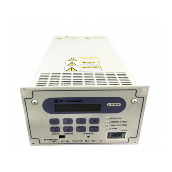
IDENTIFICATION AND FUNCTION 2.1 Power Supply Unit... - Page 21 SECTION 2 IDENTIFICATION AND FUNCTION Power Supply Unit Fig.2-1 Front Control Panel Fig.2-2 Rear Panel 263-13228...
- Page 22 2.1 Power Supply Unit (1) LCD - - - - - - - - - - - - - - - - - - - - - - - - - - - - Display operation monitor, alarm contents, settings (see Section 6.6 "Software Operation") (2) SELECT KEY - - - - - - - - - - - - - - - - - - - - - LCD display operation key, select menu (3) + KEY - - - - - - - - - - - - - - - - - - - - - - - - - - LCD display operation key, previous menu or addition...
- Page 23 SECTION 2 IDENTIFICATION AND FUNCTION This page is intentionally left blank. 263-13228...
- Page 24 CONSTRUCTION AND PRINCIPLE 3.1 Power Supply Unit...
-
Page 25: Power Supply Unit
SECTION 3 CONSTRUCTION AND PRINCIPLE Power Supply Unit The power supply unit is composed of the magnetic bearing control system and the high frequency motor system and does not use back up batteries for electrical power failure. The magnetic bearing control system controls the levitation of the rotor inside the turbo molecular pump. - Page 26 SPECIFICATIONS 4.1 Power Supply Unit 4.2 Standards Fulfilled...
-
Page 27: Power Supply Unit
SECTION 4 SPECIFICATIONS Power Supply Unit Power supply unit model EI-D1003M EI-D1103M EI-D1303M EI-D2003M TMP-803M TMP-1003M TMP-1103MP TMP-1303M TMP-2003M TMP-803MC TMP-1003MC TMP-1103MPC TMP-1303MC TMP-2003MC Suitable pump TMP-803LM TMP-1003LM TMP-1103LMP TMP-1303LM TMP-2003LM TMP-803LMC TMP-1003LMC TMP-1103LMPC TMP-1303LMC TMP-2003LMC The control cable and the motor cable are interchangeable between any pump and Exchangeable Compatibility power supply unit. - Page 28 4.1 Power Supply Unit Power supply unit model EI-D1003M EI-D1103M EI-D1303M EI-D2003M Temperatures Operation : 0 to 45 ℃ / Storage : -25 to 70 ℃ (No dew condensation) Environmental Relative Conditions 40 to 80 %RH humidity Use : Indoor, Altitude max : 2000 m...
-
Page 29: Standards Fulfilled
SECTION 4 SPECIFICATIONS Power supply unit model EI-D2203M EI-D2303M EI-D3203M EI-D3403M EI-D4203M Voltage Single phase 200 to 240 VAC ± 10% (50 / 60 Hz ± 2 Hz) Maximum 1.2 kVA 1.4 kVA 1.2 kVA 1.3 kVA 1.5 kVA Input electric power power Insulation... - Page 30 INSTALLATION 5.1 Installation of the Power Supply Unit 5.1.1 Location of the Power Supply Unit 5.1.2 Installation of the Power Supply Unit 5.1.3 Compatibility with Previous Models 5.2 Connection of Power Cable 5.3 Connection of the Pump to the Power Supply Unit...
-
Page 31: Installation Of The Power Supply Unit
SECTION 5 INSTALLATION Installation of the Power Supply Unit 5.1.1 Location of the Power Supply Unit Install and anchor the power supply unit inside a rack, which shall be located at a place where it is not exposed to direct sun ray and well ventilated. Avoid to locate it at the following places. (1) Place where it is very humid, dusty and, in addition, oil smoke, vapor, water, etc, are exist. - Page 32 5.1 Installation of the Power Supply Unit >50mm >30mm >5mm >5mm front panel installation holes (4 places ) Fig.5-1 Leave enough space around the power supply unit rack installation panel 4-M4 ± 0.2 198.1 M4 TAP, 4 PLACES +0.5 Panelcut dimensions Fig.5-2 Mount the power supply unit Power Supply Unit INSTRUCTION MANUAL...
- Page 33 SECTION 5 INSTALLATION 160mm 12mm rubber pads (4 places) φ20mm 273mm 50mm Fig.5-3 Location of rubber pads (M4×8) (Note 1) Use the prescribed screws to attach the rubber pads. Using the wrong screws can lead to damage or failure of the power supply unit. FIg.5-4 Attaching the rubber pads Control cable Fig.5-5 Space to connect the cable...
-
Page 34: Compatibility With Previous Models
5.1 Installation of the Power Supply Unit 5.1.3 Compatibility with Previous Models If previous EI-xx03M/MD/MZ power supply units (where "xx" is a number that indicates the applicable pump type) are being used installed on a rack, then optional rack mounting kit is required in order to replace these units with EI-Dxx03M power supply units. - Page 35 SECTION 5 INSTALLATION POWER SUPPLY 電源装置: EI-Dxx03M POWER ROTATION SELECT NORMAL SPEED TEMP.CONTROL START STOP RESET DISPLAY ALARM RS-232C LOCAL REMOTE CONTRAST (213) Fig.5-7 Dimensions of the Power Supply Unit with Rack Mounting Panel 206 min 4-M4 172±0.2 M4 TA 4 PLA 長角穴...
-
Page 36: Connection Of Power Cable
5.2 Connection of Power Cable Connection of Power Cable NOTICE The power input voltage of the power supply unit EI-Dxx03M (the "xx" number indicates the model of the corresponding pump) is 200 to 240 VAC ± 10%. Connect the power supply unit to the voltage specified on the rear panel label only.Connection of the power supply unit to the incorrect input voltage can cause damage to the equipment. -
Page 37: Connection Of The Pump To The Power Supply Unit
After turn on the POWER switch of the power supply unit, ALARM lamp (Fig. 2-1 (14)) lights, if an old type cable is connected. SHIMADZU 262-75369A Fig.5-10 Control Cable Connecting Sequence (See Fig. 2-2 and Fig. 5-10): (1) Turn off the POWER switch (Fig. - Page 38 5.3 Connection of the Pump to the Power Supply Unit WIDE RANGE TYPE TURBO MOLECULAR PUMP POWER SUPPLY UNIT EI-Dxx03M MAG. BRG. MOTOR AC INPUT. MOTOR CABLE CONTROL CABLE POWER CABLE AIR COOLED TYPE TURBO MOLECULAR PUMP FAN CODE POWER SUPPLY UNIT EI-Dxx03M MAG.BRG.
- Page 39 SECTION 5 INSTALLATION This page is intentionally left blank. 263-13228...
-
Page 40: Outline
OPERATION 6.1 Outline 6.1.1 Introduction 6.1.2 Operation Flowchart 6.2 Start-up Preparation 6.2.1 Start-up Preparation Sequence in LOCAL Mode 6.2.2 Start-up Preparation Sequence in REMOTE Mode 6.3 Start-up 6.3.1 Start-up Sequence in LOCAL Mode 6.3.2 Start-up Sequence in REMOTE Mode 6.4 Shutting Down 6.5 Variable Speed Operation 6.5.1 Outline 6.5.2 Operation from Start-up to Low Speed Rotation 6.5.3 Operation from Rated Speed Rotation to Low Speed Rotation 6.5.4 Operation from Low Speed Rotation to Rated... - Page 41 (See Fig. 2-1 and Fig. 2-2) The LCD (Fig. 2-1 (1)) displays the model name of the power supply unit corresponding to the pump model name (e.g. SHIMADZU EI-Dxx03M) when the power supply unit POWER switch (Fig. 2-2 (17)) is turned on.
- Page 42 6.1 Outline 6.1.2 Operation Flowchart Start-up preparation flowchart LOCAL REMOTE operation operation Set the REMOTE/LOCAL Set the REMOTE/LOCAL selection switch to LOCAL. selection switch to REMOTE. Start cooling water. Start cooling water. (for cooling water method) (for cooling water method) Turn POWER switch from Turn POWER switch from 0 (OFF) to 1 (ON).
- Page 43 SECTION 6 OPERATION Start-up flowchart Start-up flowchart (LOCAL operation) (REMOTE operation) LOCAL REMOTE operation operation Press the START switch. Input "START" signal. "ACCELERATION" signal LCD monitor mode/operation mode Display : "STOP" "ACC." output ON. ROTATION lamp lights. "ROTATION" signal output ON. Speed >...
- Page 44 6.1 Outline Shutting down flowchart Stop process gas flow? Stop process gas flow. No purge gas Stop purge gas? Stop purge gas. No valve Close valve between Close valve. backing vaccum pump? LOCAL REMOTE operation operation Press STOP switch. Input "STOP" signal. NORMAL SPEED lamp goes out.
- Page 45 SECTION 6 OPERATION Speed setting flowchart Speed setting flowchart Start-up to low speed rotation Start-up to low speed rotation (LOCAL operation) (REMOTE operation) Set the low speed value in the Set the low speed value in the LCD setting mode. LCD setting mode. (Note 1) (Note 1) Select the LOW SPEED mode...
- Page 46 6.1 Outline Speed setting flowchart Rated speed to low speed rotation Rated speed rotation or when accelerating at a speed above the low speed. LOCAL REMOTE operation operation Set the low speed value in the Set the low speed value in the LCD setting mode.
- Page 47 SECTION 6 OPERATION Speed setting flowchart Low speed to rated speed rotation Low speed rotation LOCAL REMOTE operation operation Select the NORMAL mode Cancel "LOW SPEED" signal. using the LCD setting mode/ speed setting. "∗" " disappears after the LCD monitor mode/speed display Speed <...
-
Page 48: Start-Up Preparation
6.2 Start-up Preparation Start-up Preparation Shift the REMOTE/LOCAL selection switch (Fig. 2-1 (15)) to either LOCAL or REMOTE mode. The pump can be started/stopped by pressing LOCAL START/STOP switch on the front panel of the power supply unit. the pump runs only according to input signal from REMOTE the remote-control connector (Fig. -
Page 49: Start-Up
SECTION 6 OPERATION Start-up 6.3.1 Start-up Sequence in LOCAL Mode (1) Start-up begins when the 6.2.1 "Start-up Preparation Sequence in LOCAL Mode" is complete. (2) Press START switch (Fig. 2-1 (6)). (3) ACC." is displayed on the pump monitor mode/operation mode LCD and pump acceleration starts. -
Page 50: Shutting Down
6.4 Shutting Down Shutting Down CAUTION After having operated the turbo molecular pump for evacuation of corrosive gas, keep the pump internal as vacuumed even after shutdown. Inflow of water content in the air to the pump internal would cause rapid corrosion trouble of the pump internals. The pump corrosion may result in damaging the vacuum vessel interior and other units, causing pressure fluctuation by stopping the pump and dispersal of parts. -
Page 51: Shutting Down Sequence In Remote Mode
SECTION 6 OPERATION 6.4.3 Shutting Down Sequence in REMOTE Mode (1) Input the "STOP" signal (see Table 6-3) from the remote-control connector (Fig. 2-2 (24)) and check that the "BRAKE" signal (see Table 6-3) is ON. (2) Wait until the "ROTATION" signal (see Table 6-3) turns OFF. At this time, the "BRAKE" signal (see Table 6-3) also turns OFF. -
Page 52: Variable Speed Operation
If the power supply unit is to be combined with an existing pump, modification and operational inspections are necessary. Please contact Shimadzu for detailed information. 6.5.1 Outline (1) The rotational speed settings function sets the rotational speed by selecting between the NORMAL speed mode or LOW SPEED mode. -
Page 53: Operation From Start-Up To Low Speed Rotation
SECTION 6 OPERATION 6.5.2 Operation from Start-up to Low Speed Rotation This is the procedure until low-speed rotation is achieved when the speed setting is made with the pump stopped. LOCAL Operation (1) Start-up begins when the 6.2.1 "Start-up Preparation Sequence in LOCAL Mode" is complete. -
Page 54: Operation From Rated Speed Rotation To Low Speed Rotation
6.5 Variable Speed Operation 6.5.3 Operation from Rated Speed Rotation to Low Speed Rotation This is the procedure to select low speed operation during rated speed rotation or when accelerating at a speed above the low speed.(see Fig. 6-5) LOCAL Operation (1) Set the low speed value with the setting mode/rotational speed settings/low speed setting set value on the LCD display. - Page 55 SECTION 6 OPERATION LOCAL Operation (1) Select the NORMAL mode using the setting mode/rotational speed settings/speed setting set value on the LCD display. (See Section 6.6 "Software Operation" (4).) (2) The "*" disappears after the monitor mode/speed display. (See Section 6.6 "Software Operation"...
-
Page 56: Software Operation
(Note 2) The warning output setting function is installed in some custom-specification instruments; it is not available in all instruments. Modifications are required to install this function in an instrument that does not incorporate it. Consult your Shimadzu representative for details. - Page 57 SECTION 6 OPERATION A flowchart of the entire LCD display is shown below. SELECT , + , – , SET in the flowchart indicate keys on the power supply unit front panelrepresent the LCD display. LCD display SELECT DISPLAY Fig. 6-7 Power Supply Unit Front Panel 263-13228...
- Page 58 6.6 Software Operation MENU MODE POWER SWITCH ON SELF SHIMADZU EI-Dxx03M DISPLAY DISPLAY DIAGNOSIS SELF CHEKING (2 Sec) MONITOR MODE OPERATION REMOTE #####USER MEMO###### Detail SX1= 0% SY1= 0% SX2= 0% SY2= 0% #####USER MEMO###### → P47 STOP ROT= 0% UB1=...
- Page 59 SECTION 6 OPERATION USER MEMO SETTINGS SELECT SELECT SELECT MENU SETTINGS USER MEMO INPUT USER MEMO INPUT SETTINGS SETTINGS USER MEMO INPUT SELECT USER MEMO INPUT SELECT USER MEMO INPUT ABCD123_ RS-232C SETTINGS SELECT SELECT SETTINGS RS232C BAUD RATE= 9600bps RS232C BAUD RATE=9600bps (9600bps) SELECT...
- Page 60 6.6 Software Operation In the next tables, they are shown detailed flowchart of LCD display. (1) MONITOR MODE In monitor mode operation status of pump can be identified. If key DISPLAY is pushed in menu mode, the LCD changes into monitor mode. The LCD changes automatically into monitor mode after start or stop operation.
- Page 61 SECTION 6 OPERATION (Note 2) Pump Operation Mode LCD Display Pump Operation NORMAL Normal rotation ACC. Motor acceleration BRAKE Motor brake deceleration STOP Motor stop IDLE Free operation E-STOP Error occurs (stop) E-BRAKE Error occurs (motor deceleration) E-IDLE Error occurs (free operation = motor stop) (Note 3) Any character can be entered in the USER MEMO from the menu mode "SETTINGS/ USER MEMO INPUT".
- Page 62 6.6 Software Operation (2) ALARM MODE Alarm mode is a mode to display detected alarm contents and alarm history. If key DISPLAY is pushed in monitor mode, the LCD changes into alarm mode. The LCD changes automatically changes into alarm mode when an alarm is detected. See Table 7-6 "Table of Alarms" and Table 7-7 "Table of Warnings"...
- Page 63 SECTION 6 OPERATION (3) MENU MODE/TIMER Mode Operation and LCD Display Description of Display MENU MENU MODE MENU MENU INTEGRATING TIMER INTEGRAING TIMER TIMER MODE TITLE INTEGRA The pump's integrated run time is SELECT displayed. TING SELECT TIMER INTEGRATING TIMER INTEGRATING TIMER at 2003/12/31 23:59 RUN TIME=99999HR RUN TIME=99999HR...
- Page 64 6.6 Software Operation The number of alarms that occur for the magnetic bearing system at speeds exceeding 80% of the rated speed is counted. If this number exceeds 10, alarm code 11 (number of high-speed SELECT INTEFRATING TIMER at 2003/12/31 23:59 touch-downs alarm) MB ALARM=999 from2003/12/31 23:59...
- Page 65 (Note 1) The warning output setting function is installed in some custom-specification instruments; it is not available in all instruments. Modifications are required to install this function in an instrument that does not incorporate it. Consult your Shimadzu representative for details. 263-13228...
- Page 66 6.6 Software Operation Mode Operation and LCD Display Description of Display RS-232C Baud rate setting SETTINGS SETTINGS Press the + or key to select a baud RS232C rate between 19.2k, 9600, 4800, 2400, or 1200. SELECT BAUD RATE=9600bps SELECT (9600bps) RS232C BAUD RATE=9600bps Previous Setting BAUD RATE=9600bps...
- Page 67 SECTION 6 OPERATION Mode Operation and LCD Display Description of Display ROTATIONAL SPEED Speed display setting SETTINGS SETTINGS ROT.SPEED Press the + or - key to select between %, rpm, or rps. SELECT DISPLAY=% SELECT ROT.SPEED DISPLAY=% (% ) DISPLAY=% (% ) Previous Setting The format of the motor speed display in the pump monitor mode is...
- Page 68 6.6 Software Operation Mode Operation and LCD Display Description of Display REMOTE- “ALARM” signal setting of remote- CONTROL control signal (Note 2) SETTINGS SIGNAL Press the + or - key REMOTE SIGNAL MODE to select between SETTINGS EI-03 or SEMI E74. SELECT ALARM=EI-03 SELECT...
- Page 69 232C or RS-485 set it in the cases that wants to use hardware inter rock. *1 When set to EI-03, behavior of remote-control signals is the same as SHIMADZU Turbo Molecular Pump power supply "EI-03MD" series. *2 When set to SEMI E74, behavior of remote-control signals conform to SEMI E74 standard "Specification for vacuum Pump Interface-Turbomolecular Pumps"...
- Page 70 6.6 Software Operation (5) MENU MODE/SELF TEST Mode Operation and LCD Display Description of Display SELF Select YES and press the SET key to TEST execute self-diagnosis of the magnetic MENU bearing sensor. If an abnormality is SELF TEST discovered by self-diagnosis, alarm codes SELECT 81 to 85 occur.
-
Page 71: Remote-Control Connector
SECTION 6 OPERATION Remote-Control Connector 6.7.1 Specifications The controller is provided with remote- control connector for connection with remote operation, alarm signals, etc. Use this connector and a cable with shield as INSIDE OF POWER UNIT necessary. The shield of the cable should be connect to case of Remote-connector. - Page 72 6.7 Remote-Control Connector Table 6-3 Remote-Control Signals (Default Settings) Classifi- Signals Pin No. Operation Electric spec. cation (15) Starting operation on GND and short- START circuiting (Note 1) (16) Stopping operation on GND and circuit STOP opening (Note 1) (Note 2) Inputs (17) Resetting operation on GND an short- Contact input...
-
Page 73: Compatibility With Previous Models
SECTION 6 OPERATION Fig. 6-9 Arrangement of Remote-Control Connector Pins (The power supply unit rear panel attachment connectors, as viewed from the front) 6.7.2 Compatibility with Previous Models 6.7.2.1 Replacing the EI-xx03M/MD Power Supply Unit CAUTION The transistor output has been discontinued. The pins that were used for that output are now assigned to different functions.If wires were connected to these pins with previous models, then simply making the connection as it is could result in a malfunction on the system controller end. - Page 74 6.7 Remote-Control Connector Power Supply ALARM Signal REMOTE Signal Unit When the power supply is turned off, the Remote signal is forcibly off during EI-xx03M/MD ALARM signal is off. regenerative braking. EI-Dxx03M When the power supply is turned off, the Remote signal during regenerative SEMI E74 ALARM signal is on.
-
Page 75: Replacing Ei-Xx03Mz Power Supply Units
SECTION 6 OPERATION 6.7.2.2 Replacing EI-xx03MZ Power Supply Units If using the remote control signal for previous EI-xx03MZ power supply units (where "xx" is a number that indicates the applicable pump type), then the following checks and changes to settings are necessary when replacing the unit with an EI-Dxx03M model. Change the "ALARM"... - Page 76 6.7 Remote-Control Connector Table 6-5 EI-xx03MZ vs. EI-Dxx03M Pin Configuration Comparison Chart -After Changing Settings (SEMI E74 Standard Mode) Pin numbers EI-Dxx03M Singal type Signals Compatibility EI-xx03MZ SEMI E74 Standard Mode START STOP INPUT RESET LOW SPEED GND(COMMON) 17:Make contact 29:Make contact ROTATION 19:Common 30:Common...
- Page 77 SECTION 6 OPERATION This page is intentionally left blank. 263-13228...
- Page 78 TROUBLESHOOTING 7.1 Nothing Happens After an Operation is Made 7.2 Power Failures 7.3 Vacuum Pressure Rise 7.4 Abnormal Noise and/or Vibration 7.5 Alarm Detection Capabilities...
-
Page 79: Section 7 Troubleshooting
Blown fuse (F1, F2) Replace blown fuse. POWER switch fails to the off Replace POWER switch. Consult the position. nearest Shimadzu service company. START switch REMOTE/LOCAL selection switch Set the REMOTE/LOCAL selection switch pressed but turbo in the REMOTE position. -
Page 80: Power Failures
Supported by Touchdown Bearing Rotational Speed Before Period of Time Before Support Power Supply Pump Model Support by Touchdown by Touchdown Bearing Model Bearing Note 1) TMP-803M/MC/LM/LMC EI-D1003M 7200rpm about 4 minutes TMP-1003M/MC/LM/LMC TMP-1103MP/MPC/LMP/LMPC EI-D1103M 7200rpm about 4.5 minutes TMP-1303M/MC/LM/LMC EI-D1303M 7800rpm about 5.5 minutes... -
Page 81: Power Failure Counter-Operation
SECTION 7 TROUBLESHOOTING 7.2.1 Power Failure Counter-Operation Table 7-3 shows the counter-operations against power supply failure which occurred while the pump rotor is normally rotating. Table 7-3 Counter-Operations Against Power Supply Failure Interruption time 1 second or less Over 1 second Interrupt/re-supply During interruption After re-supply During interruption... -
Page 82: Vacuum Pressure Rise
7.3 Vacuum Pressure Rise Vacuum Pressure Rise A rapid rise of vacuum pressure in the turbo molecular pump causes the internal motor of the turbo molecular pump to start braking and the ALARM lamp (Fig. 2-3 (14)) lights. Abnormal Noise and/or Vibration Should the turbo molecular pump ever generate abnormal noise and/or vibration, the turbo molecular pump operation is to be stopped immediately. -
Page 83: Movement In Alarm Detection Capabilities (Warning)
SECTION 7 TROUBLESHOOTING 5. The pump start the protective operations shown in Table 7-6 "Table of Alarms." 6. The detection error is recorded in the error log. 7.5.2 Movement in Alarm Detection Capabilities (WARNING) The warning output setting in the menu mode "SETTINGS / WARNING DISPLAY" item on the LCD changes the operation when a warning occurs. - Page 84 Remedy 11=TD COUNTER The number of high speed The touch-down bearing may have LIMIT or power failure touch- deteriorated. Consult Shimadzu or an 12=PF COUNTER downs has exceeded the approved service company regarding LIMIT prescribed number. replacement of the touch-down bearing.
- Page 85 SECTION 7 TROUBLESHOOTING Sect LCD Display Possible Cause Remedy Check that the ambient temperature around the pump is within the specified range. For the air-cooled models, check that the cooling fan is operating and cooling High pump unit is not hindered by peripheral objects. temperature.
- Page 86 7.5 Alarm Detection Capabilities Sect LCD Display Possible Cause Remedy Check that the ambient temperature around the power supply unit is within 44=EI:CPU ERROR Abnormal operation the specified range. 66=MB:DSP ERROR of circuit in the Check that equipment causing noise is 67=MB:DSP OVERFLOW power supply unit.
- Page 87 SECTION 7 TROUBLESHOOTING Table 7-5 If the ALARM Lamp Flashes Sect LCD Display Possible Cause Remedy 81=MB:SELFCHECK X1 Rattling of the Deterioration of the protective bearing is 82=MB:SELFCHECK Y1 protective bearing likely. Overhaul as soon as possible to 83=MB:SELFCHECK X2 becomes avoid damage to the protective bearing 84=MB:SELFCHECK Y2 pronounced.
- Page 88 7.5 Alarm Detection Capabilities Table 7-6 Table of Alarms Alarm LCD Display Cause Protective Action Code Counts of the high speed touch- 11=TD COUNTER LIMIT down counter exceeded the specified number. Start-up impossible Counts of the power failure touch- (detected during power 12=PF COUNTER LIMIT down counter exceeded the supply self-diagnostics)
- Page 89 SECTION 7 TROUBLESHOOTING Alarm LCD Display Cause Protective Action Code Pump does not accelerate to 80% of the designated speed or 48=EI:ACCEL OVERTIME low-speed setting within the specified time after start-up. Pump fails to rotate within 15 49=TMP:CAN NOT START seconds after start-up. Continuous excessive vibration 51=MB:VIBRATION2 X1 of the magnetic bearing.
- Page 90 7.5 Alarm Detection Capabilities Table 7-7 Table of Warnings Alarm LCD Display Causes Protective Action Code Results of magnetic bearing Operation is possible 81=MB:SELFCHECK X1 sensor self-diagnostics are (detected during power abnormal. supply self-diagnostics). 82=MB:SELFCHECK Y1 83=MB:SELFCHECK X2 84=MB:SELFCHECK Y2 85=MB:SELFCHECK Z Vibrations of the magnetic 86=MB:VIB.
- Page 91 SECTION 7 TROUBLESHOOTING This page is intentionally left blank. 263-13228...
-
Page 92: Appendix A Communications
Appendix A COMMUNICATIONS A1. GENERAL SPECIFICATION A2. INTERFACE SPECIFICATION A2.1 RS-232C A2.2 RS-485 A3. POWER SUPPLY TO COMPUTER CONNECTION A3.1 Communication Cable Connection A3.2 Serial Communications Baud Rate Configuration A3.3 RS-485 Multi-drop Settings A4. SERIAL COMMUNICATIONS PROTOCOL A5. TABLE OF COMMANDS A6. COMMAND DESCRIPTION A6.1 Operation Mode A6.2 Operation A6.3 Run Status A6.4 Parameters A6.5 Events A6.6 Timer A6.7 History ... -
Page 93: General Specification
Appendix A COMMUNICATIONS GENERAL SPECIFICATION The EI-D03M series power supply units contain serial interfaces conforming to RS-232C and RS-485 specifications. The following functions are available by connecting a computer with communication capacity to these interfaces and creating the appropriate software. The RS-232C and RS-485 interfaces can be used simultaneously, permitting simultaneous access from two computers. -
Page 94: Interface Specification
A2. INTERFACE SPECIFICATION INTERFACE SPECIFICATION A2.1 RS-232C A2.1.1 Transmission Specification Interface RS-232C Synchronous system Asynchronous 1200, 2400, 4800, 9600 and 19.2k bits per second Transmission rate (See Section 6.6 “Software Operation” (4) for settings). Start bit: 1 Data bits: 8 Character configuration Parity: None Stop bits: 1... - Page 95 Appendix A COMMUNICATIONS a. Cable wiring connections for 9-pin to 9-pin connector cables Connector of power supply Connector of computer D-Sub 9pin D-Sub 9pin Female Female b. Cable wiring connections for 9-pin to 25-pin connector cables Connector of power supply Connector of computer D-Sub 9pin Female D-Sub 25pin Male...
-
Page 96: Communications Connector
A2. INTERFACE SPECIFICATION A2.2 RS-485 A2.2.1 Transmission Specification Interface RS-485 Synchronous Asynchronous system 1200, 2400, 4800, 9600 and 19.2k bits per second Transmission rate (See Section 6.6 “Software Operation” (4) for settings). Start bit: 1 Data bits: 8 Character configuration Parity: None Stop bits: 1 Flow control None... -
Page 97: Cable
Appendix A COMMUNICATIONS b. Multi-drop function ON Power Supply Unit 1 COMPUTER 120Ω 120Ω Cable connector D-Sub 9pin Male Power Supply Unit 2 Cable connector D-Sub 9pin Male Power Supply Unit N 120Ω 120Ω Cable connector D-Sub 9pin Male Fig. A-3 Example of RS-485 cable wiring connections (Multi-drop function ON) (2) Cables used RS-485 is a differential transmission and use twisted-pair cables in combinations as shown in Figs. -
Page 98: Communication Cable Connection
A3. POWER SUPPLY TO COMPUTER CONNECTION POWER SUPPLY TO COMPUTER CONNECTION A3.1 Communication Cable Connection Turn off the power supply unit and the computer to be connected. Connect the RS-232C connector on the power supply unit front panel or the RS-485 connector on the rear panel (refer to section 2.2 in this document, "Power Supply Unit") to the communications port of the computer with a cable, referring to section A2. -
Page 99: Serial Communications Protocol
Appendix A COMMUNICATIONS SERIAL COMMUNICATIONS PROTOCOL Communications software, between the power supply and customer equipment should be design according to the following specifications. A4.1 Basic Message Structure A basic transmit and receive message begins with the characters "MJ" and ends with a carriage return code (0dH : xxH means hexadecimal code). -
Page 100: Command To Answer Time-Out: 1 Sec
A4. SERIAL COMMUNICATIONS PROTOCOL A4.3 Command to Answer Time-out: 1 sec. Delays between COMMAND and ANSWER messages, longer that 1 sec., shall be considered as a transmission line failure and special considerations should be made to re-send the message. The power supply re-sends a COMMAND, if it does not receive and ANSWER within a one second period. -
Page 101: Outline Of Multi-Drop Communications
Appendix A COMMUNICATIONS Calculation Example In the received character string "MJ01LS97$" ($ represents the carriage return code), the check sum code is represented by the last two characters: "97". The checksum for the received character string is calculated as follows. The result shows that the received character string is correct. -
Page 102: Table Of Commands
A5. TABLE OF COMMANDS TABLE OF COMMANDS Table A-2 Table of Commands Command Command/ Sub-command character Type Name character answer string string Operation mode check None Command On-line request None Off-line request None Operation Local None mode Remote None Answer RS-232C None RS-485 None START operation... - Page 103 Appendix A COMMUNICATIONS Command Read alarm history History Send alarm history xxx...xxx Answer No history data Read settings Command Write settings aabbbb Send settings value aabbbb Answer Settings Invalid setting number Read user memo None Command Write user memo xxx...xxx Answer Send user memo xxx...xxx Shared answer...
- Page 104 A5. TABLE OF COMMANDS Table A-3 Table of Parameters Name Range Description and format Model identification Value representing the model. Fixed Example: EI-D3203M → 3203 number Rotational speed / 10 Rotational speed 0000 to 5000 Example: 15000 rpm → 1500 Motor drive current x 10 Motor current 0000 to 0150 Example: 2.3 A →...
- Page 105 Appendix A COMMUNICATIONS Table A-4 Table of Timer Name Range Description and format Read the timer value in the “MENU MODE / INTEGRAL TIMER / RUN TIME” on the LCD display. (Can not be Run time 00000 to 99999 reset. Reset date is invalid.) Example: 0 →...
- Page 106 A5. TABLE OF COMMANDS Number Item Data Comments of bytes 55, 65 Temperature control set temperature when the (EI-D303MT to EI- Temperature failure occurred. Format is equivalent to last 2 D1303MT) control set characters of 08 in Table A-3. (Valid only for a 55, 65, 75 temperature power supply with a temperature control...
- Page 107 Appendix A COMMUNICATIONS Table A-6 Table of Settings Name Range Description and format Read or change the set values in the “MENU / SETTINGS / TEMP.CONTORL / TEMP.CONTROL” on the LCD display. Temperature control 0000 / 0001 0000: Temperature control function on on/off 0001: Temperature control function off (Valid only for a power supply with a temperature control...
-
Page 108: Command Description
A6. COMMAND DESCRIPTION COMMAND DESCRIPTION A6.1 Operation Mode Operation mode check Enables operation mode verification (LOCAL / REMOTE / RS-232C / RS-485) Action: Power supply returns an ANSWER showing present operation mode. ON-LINE request If the current operation mode is REMOTE, the operation mode is shifted to RS- Commands 232C or RS-485. -
Page 109: Operation
Appendix A COMMUNICATIONS A6.2 Operation START Operation This command is the equivalent of pressing the front panel START switch. Action: The turbo molecular pump starts accelerating and sends the “Acceleration Start” answer. STOP Operation This command is the equivalent of pressing the front panel STOP switch. Action: The turbo molecular pump starts decelerating and sends the “Deceleration Commands Start”... -
Page 110: Run Status
A6. COMMAND DESCRIPTION A6.3 Run Status Run Status Check Commands This command requests the current power supply status. Stop This answer is returned when the pump stops. Equivalent to the monitor mode/ STOP run status on the LCD display. For a normal status, "00" is returned as the sub-command. If a warning has occurred, the 2-character alarm code is returned as the sub-command. -
Page 111: Parameters
Appendix A COMMUNICATIONS A6.4 Parameters Read paramater Commands Reads the parameter value for a designated parameter number. Sends the 2-character parameter number as the sub-command. Send parameter Returns the parameter value for the designated parameter number. The 2- character parameter number + 4-character parameter value is returned as the sub- command in the format shown in Table A-3 "Table of Parameters."... - Page 112 A6. COMMAND DESCRIPTION A6.6 Timer Read timer Reads the timer value for a designated timer number. Sends the 2-character timer number as the sub-command. Clear timer Clears the timer value for a designated timer number. Commands Sends the 2-character timer number as the sub-command. Write timer Overwrites the set value for a maintenance call timer.
- Page 113 Appendix A COMMUNICATIONS A6.8 Settings Read settings Reads the set value for a designated settings number. Sends the 2-character settings number as the sub-command. Commands Write settings Overwrites the set value for a designated settings number. Sends the 2-character settings number + 4-character set value data as the sub- command.
- Page 114 A7. RS-232C COMMANDS / ANSWERS RS-232C COMMANDS / ANSWERS (SEND AND RECEIVE Examples) Table A-7 RS-232C COMMANDS / ANSWERS (SEND AND RECEIVE Examples) Send/ Computer Power Type Receive Description Remarks (Host) *1 Supply Operation Mode → MJ01LS97$ Check MJ01LL90$ LOCAL MJ01LR96$ REMOTE ←...
- Page 115 Appendix A COMMUNICATIONS Send/ Computer Power Receive Description Remarks Type (Host) *1 Supply → MJ01CS8E$ Run Status Check MJ01NS00F9$ Stop MJ01NA00E7$ Acceleration MJ01NB00E8$ Deceleration MJ01NN00F4$ Normal Rotation MJ01FS1C05$ Failure Stop LCD: “TMP:CAN NOT START” ← MJ01FF32E9$ Failure Idle LCD: “EI:DC-DC OVERTEMP” Run Status Failure MJ01FR15F6$...
- Page 116 A7. RS-232C COMMANDS / ANSWERS Send/ Computer Power Receiv Description Remarks Type (Host) *1 Supply e *2 MJ01GA01E Read Alarm → History 01 History History: 01 Date & time: 2003/04/01 12:00 Alarm: power failure Status: normal rotation Rotational speed: 100% MJ01GB01030 Motor current: 1.0 A 401120015NN °...
-
Page 117: Relation Of Local Mode To Remote Mode
Appendix A COMMUNICATIONS RELATION OF LOCAL MODE TO REMOTE MODE OPERATIONS (1) Input of front panel switch is only effective when REMOTE / LOCAL selection switch is in "LOCAL" mode. (2) When the selection switch is in "REMOTE" mode, "REMOTE" input signal only is effective under initial status. -
Page 118: Troubleshooting
A9. TROUBLESHOOTING TROUBLESHOOTING A9.1 No Message can Transmit and Receive (1) Start the pump in LOCAL mode and check if the event command of Rotation start can be received in the timing at which ROTATION lamp lights. Could be received >> check if command from connected computer can be received or not, using another computer, etc. - Page 119 Appendix A COMMUNICATIONS This page is intentionally left blank. A-28 263-13228...
- Page 120 Index Index ALARM ..............69 Alarm history ........... 14、15、49 Alarm mode ............43、49 Control Cable ............4、24 How to install the unit onto a rack ......18 Menu mode ........43、50、52、57 Monitor mode ............47 Motor Cable ............. 4 power failure ...........14、15 Power switch ............
- Page 121 Index This page is intentionally left blank. Power Supply Unit Index-2 263-13228 INSTRUCTION MANUAL...
- Page 122 Excerpt from No. FE8A-0049F Declaration of Conformity SHIMADZU CORPORATION SEMICONDUCTOR EQUIPMENT DIVISION Address :380-1,HORIYAMASHITA,HADANO-CITY, KANAGAWA, 259-1304, JAPAN as the Manufacturer declares in sole responsibility that the following product Product Name Turbo Molecular Pump Model name , P/N Vacuum Pump Power Supply...
- Page 123 TMP Evaluation Form Please fill out this evaluation form and attach to the product when you send it back to Shimadzu Service Center for repair service, etc. When you fill out this form, please describe the details as much as possible.
Need help?
Do you have a question about the EI-D1003M and is the answer not in the manual?
Questions and answers