
Subscribe to Our Youtube Channel
Related Manuals for WPI SI-MT

Summary of Contents for WPI SI-MT
- Page 1 SI-MT/SI-MKB/SI-HTB Signal Conditioning Amplifi er System for Muscle Testers INSTRUCTION MANUAL Serial No._____________________ 112014 World Precision Instruments...
- Page 2 • Using a separate reference channel, imaging, making this equipment more affordable. A breakthrough in WPI patented ultra-stable, continuous ratio calculations technology allows the SI-BF-100 to use automatically compensate for LED wavelengths below 380nm and produce intensity drift.
-
Page 3: Table Of Contents
Features ..............................3 Cautions and Warnings ........................3 Parts List ..............................3 Unpacking ..............................3 INSTRUMENT DESCRIPTION ........................4 Signal Conditioning Amplifi er (SI-MT/SI-MKB/SI-HTB) .............. 4 Front Panel ............................4 Back Panel ............................5 SI-BAM21-LCB ............................6 Features ..............................6 How the Amplifi... - Page 4 SI-H Muscle Testers Turning On/Off the Laser ......................32 Adjusting the CCD Offset ......................32 Setting the Tissue Distance ......................32 Adjusting the CCD Sensitivity ......................33 Setting the Camera (CCD) Mode ....................33 Aligning the Laser and the Camera ..................33 Calibrating the Camera .........................35 Display Laser Diffraction Pattern on an Oscilloscope ............36 Understanding the Display ......................36 Setup ..............................37...
-
Page 5: About This Manual
Please read these carefully. NOTES and TIPS contain helpful information. Fig. 1 (Left) SI-MT is a convenient platform for all standard mechanical experiments on intact muscle preparations. Fig. 2 (Right) The SI-MKB platform can be used for mechanical and optical studies of intact or skinned muscle fi... -
Page 6: Introduction
NOTE: The system is fl exible and confi gurable. A variety of modules are available for the Signal Conditioning Amplifi er System, and you can mix and match the modules to suit your requirements. For this manual, we will only discuss the modules used with an SI-MT, SI-HTB or SI-MKB system. -
Page 7: Features
Concealed damage should be reported at once to the carrier and an inspection requested. Please read the section entitled “Claims and Returns” on page 44 of this manual. Please contact WPI Customer Service if any parts are missing at 941.371.1003 or customerservice@wpiinc.com. -
Page 8: Instrument Description
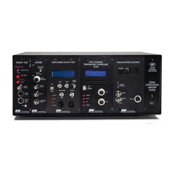
SI-H Muscle Testers INSTRUMENT DESCRIPTION Signal Conditioning Amplifi er (SI-MT/SI-MKB/SI-HTB) Front Panel Optical Anti Sarcomere Temperature Linear Power Transducer Oscillation Spacing Control Motor Switch Amplifier Unit Module Module Controller Fig. 4 The front panel of a Signal Conditioning Amplifi er System confi gured for a Muscle Tester shows the SI-BAM21-LCB, the SI-AOSUB, The SI-SARCAM, the SI-MOTDB and the SI-TCMB2. -
Page 9: Back Panel
SI-MT/SI-MKB/SI-HTB Temperature Control Module–When temperature control is required, the SI-TCM2 is used. It can control two cuvettes simultaneously, using digital control to maintain a constant temperature. It has both high and low alarm warnings which can be user defi ned. -
Page 10: Bam21-Lcb
SI-H Muscle Testers NOTE: The 16 plugs marked with A or B are for future development. They are not used at this time. SI-BAM21-LCB The SI-BAM21-LCB KG Optical Force Transducer Amplifi er is used in conjunction with the SI-H tissue bath and muscle physiology systems. The SI-BAM21-LCB powers the force transducer and converts the output of the transducer to an amplifi... -
Page 11: Front Panel
Use the provided potentiometer adjustment tool (WPI#13661) to calibrate the output of the amplifi er to the range of forces that will be measured by the transducer. See "Calibrating the SI-BAM21- LCB"... -
Page 12: Pf100
Align the pins, and insert the connector until it is fully seated. Digital Interface–This connection is a legacy interface for classic SI-H equipment. NOTE: When the SI-MT or SI-MKB electronics are confi gured at the factory for the muscle Tester systems, the signal is routed internally from the SI-BAM21-LCB module to the SI-AOSUB module. -
Page 13: Aosub
SI-MT/SI-MKB/SI-HTB Cutoff Frequency Selection Buttons–Use the Up and Down buttons to change the frequency of the fi lter applied to the input signal. Signal In BNC– The output signal from the transducer amplifi er comes into the SI-PF100 through this port (LPF IN). If the signal is not routed along the backplane, connect the SI- BAM21-LCB Force Output to this port. -
Page 14: Sarcam
Anti-oscillation Frequency Adjustment potentiometer– Use the included potentiometer adjustment tool (WPI #13661) to rotate the potentiometer until the force transducer resonates. During this procedure, the number of segments in the Signal Amplitude LED array that light up increases as the resonance frequency approaches that of the force transducer. - Page 15 SI-MT/SI-MKB/SI-HTB the pattern is symmetrical with respect to the center beam. When the scan arrives at the part of the CCD chip which is hit by the fi rst order diffraction of the pattern, the output voltage increases to a peak level, and the fi rst order of diffraction is captured (Fig. 11).
-
Page 16: Front Panel
SI-H Muscle Testers contraction. Broadening of the sarcomere distribution indicates increased sarcomere disarray. Often this is not reversible and indicates loss of sarcomere integrity and reduced viability of the muscle preparation. Reduction in peak force and simultaneous increased resting tension can then be further indication of a dying muscle; the preparation needs to be replaced. -
Page 17: Motdb
SI-MT/SI-MKB/SI-HTB is running. During normal operations, this display can show the calculated (actual) sarcomere spacing, the fi rst order diffraction distance or the signal amplitude. During confi guration, this display shows parameters and confi rmation messages. Laser Intensity–Rotate this dial to change the intensity of the laser's power output. -
Page 18: Features
SI-H Muscle Testers Fig. 15 The Linear Motor is an optional part for the SI-MT or SI-MKB systems. The position of the linear motor is determined by a combination of the data from the controller indicating the current position and the DC value applied to the front panel at the Position In port. -
Page 19: Front Panel
Power LED Fig. 16 The Linear Motor Controller Motor Connector–Use this port to connect the linear motor used with the SI-MT or SI- MKB muscle testers. The motor is setup and calibrated to the Linear Motor Controller that is shipped with it. The motor and controller have a maximum range of motion of ±3.5mm from the center of travel. -
Page 20: Tcm2B
SI-H Muscle Testers SI-TCM2B The SI-H Temperature Control Unit is designed for use with the SI-H line of muscle physiology research platforms. It maintains the temperature of an SI-H cuvette up to 45ºC. This unit is available in a standalone model or as a module for the Signal Conditioning Amplifi... -
Page 21: Colub
1 temperature, Channel 2 temperature and both. The Setup button rotates through the array of confi gurable parameters. The Up and Down buttons are used to adjust the parameters. Cuvette Connections–Use these ports to connect SI-H cuvettes used with the SI-MT and SI-MKB platforms. SI-COLUB The SI-COLUB Constant Load Module can be used in one of three different modes. - Page 22 SI-H Muscle Testers In constant load experiments, the initial length of the muscle is set using the manual adjustments of the muscle research platform. While the muscle is held at its initial length, it is stimulated with tetanizing pulses so that the muscle develops its isometric force. These stimulus pulses are controlled by the stimulation protocol created in MDAC and sent from the analog stimulus output of the LabTrax 8/16.
- Page 23 SI-MT/SI-MKB/SI-HTB • Constant Load–This mode maintains a constant load on the tissue sample. If capture command LabTrax 8/16 triggers Capture triggered, Capture Command sets F at level of Force Step captured F sets k (%) CL Command receives F measurement k×F...
- Page 24 IMPORTANT NOTE: THE SI-COLUB unit can only be used on tonically contracting muscle tissue (for example, during a tetanic contraction). For equivalent experiments in cardiac muscle and skeletal twitch contractions, the AFTERLOAD unit is needed. Contact WPI for further information.
- Page 25 SI-MT/SI-MKB/SI-HTB Stretch Control Knob–This 12-position dial adjusts the response time of the stretch and slack periods of the tissue sample. The setting you choose depends on the sensitivity of your force transducer and the strength of your sample tissue. Force Step Dial–During a tonic contraction, activation of the SI-COLUB unit causes the force to drop to the level, which is set using with the Force Step dial.
-
Page 26: Connecting The Signal Conditioning Amplifi Er System
(Optional) If a motor is used, an SI-PF100 programmable fi lter or an SI-AOSUB anti-oscillation unit is necessary to minimize vibration. When the SI-MT or SI-MKB electronics are confi gured at the factory with an SI-PF100 or SI-AOSUB, the signal is routed internally from the SI-BAM21-LCB module to the SI-PF100 or SI-AOSUB module. - Page 27 SI-MT/SI-MKB/SI-HTB programmable fi lter module (or SI-AOSUB anti-oscillation module) are not connected to each other through the backplane of the Signal Conditioning Amplifi er System, these two modules must be connected through ports on the front panels of the modules. Use a BNC-BNC cable to connect the Force Output...
- Page 28 SI-H Muscle Testers Constant Load External Loop Bypass CL (toggle switch–down EXT CMD (toggle – position) switch–up position) Output (AO or DO) This connection is not This connection is not Bypass from LabTrax 8/16 that used. IF desired, you can used.
-
Page 29: Operating Instructions
SI-MT/SI-MKB/SI-HTB OPERATING INSTRUCTIONS Turning the System On For convenience, the Signal Conditioning Amplifi er System has two power switches, and both must be on to power the system. One is located on the back panel, and one is on the front. Both switches must be on to power the system. Verify that the power cord is properly installed and plugged into an AC power outlet. - Page 30 Mount the force transducer on the calibration stand on the base of the SI-MT, SI- MKB or SI-HTB system. NOTE: The calibration stand holds the force transducer and its tissue mount in the proper orientation for an accurate calibration.
- Page 31 SI-MT/SI-MKB/SI-HTB Force Transducer Assembly Tissue Mounting Hook Calibration Stand Fig. 22 When the force transducer is properly mounted in the calibration stand on the muscle tester, the force transducer is held at the same angle used when making measurements. Set the Gain switch on the front panel of the SI-BAM21-LCB to the gain (X1-X10) that is suitable for the mass being used for the calibration of the selected transducer.
-
Page 32: Making Measurements
The SI-BAM21-LCB gain multiplier setting is selected with an internal jumper that is confi gured at the factory for use with the muscle tester system of your choice (SI-MT, SI-MKB, SI-HTB). The X1 setting (SI-MT/SI-HTB) allows for 1X, 2X, 5X and 10X gains. -
Page 33: Using The Anti-Oscillation Unit
The anti-oscillation fi lter is adjusted at the factory using the transducer that is supplied with the SI-MT, SI-MKB, SI-HTB, or SI-CTS system. Normally, the fi lter does not need to be reset, unless a different force transducer is connected to the unit. To adjust the anti- oscillation fi... - Page 34 SI-H Muscle Testers Using the potentiometer adjustment tool provided with the signal conditioning amplifi er system, rotate the calibration screw of the Anti-oscillation Frequency Adjustment potentiometer completely to the left (counter-clockwise). The anti- oscillation frequency is now set to the lowest possible level. Turn the Pulser Amplitude Adjustment knob completely to the left (counter-clock- wise).
-
Page 35: Using The Sarcomere Length Unit
SI-MT/SI-MKB/SI-HTB Using the Sarcomere Length Unit Setup Turn on the system. See "Turning the System On" on page 25. Line up the laser connector with the port labeled Laser on the SI-SARCAM module and press it into place. Line up the camera connector with the port labeled CCD on the SI-SARCAM module and press it into place. -
Page 36: Turning On/Off The Laser
SI-H Muscle Testers Turning On/Off the Laser For safety reasons, the laser is always disabled at startup. Press the Setup button. The state of the laser displays (LASER DISABLED or LASER ENABLED). LASER DISABLED Fig. 27 Press the Up or Down button to change the laser state. Press the Up or Down button to change the laser state. -
Page 37: Adjusting The Ccd Sensitivity
SI-MT/SI-MKB/SI-HTB Adjusting the CCD Sensitivity Press the Setup button until “ CCD Sensitivity" displays. The camera's sensitivity can range from 1 (minimum) to 10 (maximum). By default the sensitivity is set to the mini- mum (1). To modify the sensitivity, press the Setup button. - Page 38 SI-H Muscle Testers Fig. 32 The cross hair mark is etched on the front of the camera, which is mounted just behind the optical cuvette. SI-SARCAM Front SI-SARCAM Back Camera CCD Detector Cross Hair Mark Chip Optical Cuvette Camera X-Y Adustment Knob Laser Camera Height...
-
Page 39: Calibrating The Camera
SI-MT/SI-MKB/SI-HTB signal. To do this, press the Display button on the controller to view the signal amplitude. This shows the detected fi rst order diffraction of the laser pattern. This amplitude is maximal if the focused light hits the sensitive area of the detector chip. -
Page 40: Display Laser Diffraction Pattern On An Oscilloscope
SI-H Muscle Testers Display Laser Diffraction Pattern on an Oscilloscope In order to display the laser diffraction pattern on an oscilloscope connect the Sync BNC connector with the external trigger input of an oscilloscope. The trigger signal is 5.0V. It jumps high when the scan begins. Fig. -
Page 41: Setup
SI-MT/SI-MKB/SI-HTB NOTE: The maximum temperature the sensor can monitor is 62.9ºC. If a channel has no cuvette plugged in, the display will default to the maximum temperature display. Alarm State–If the temperature of the cuvette is within the defi ned range, OK displays on the screen. -
Page 42: Adjusting The Setpoint
SI-H Muscle Testers Adjusting the Setpoint Press the Setup button. The Channel 1 setpoint displays. To modify the Channel 2 setpoint, press the Setup button until “CH2 Setpoint” displays. CH 1 Setpoint º 37.0 Fig. 40 Press the Up and Down buttons to adjust the Channel 1 Setpoint. Press the Up or Down button to adjust the setpoint. -
Page 43: Enabling/Disabling The Alarms
SI-MT/SI-MKB/SI-HTB Press the Up or Down button to adjust the backlight level. Press the Display button to save the confi guration and return to the normal display. Enabling/Disabling the Alarms By default the alarms are disabled. When enabled, the unit will emit a beep when an alarm state occurs. -
Page 44: Maintenance
SI-H Muscle Testers MAINTENANCE The Signal Conditioning Amplifi er System is maintenance free. However, to protect it, follow these guidelines: • Place the Signal Conditioning Amplifi er System in a clean, dry location. • Keep liquids away from the Signal Conditioning Amplifi er System connections. ACCESSORIES SI-BAM21-LCB Accessories Part Number... -
Page 45: Troubleshooting
NOTE: If you have a problem/issue with that falls outside the defi nitions of this troubleshooting section, contact the WPI Technical Support team at 941.371.1003 or technicalsupport@wpiinc.com. WORLD PRECISION IN STRU MENTS... -
Page 46: Specifications
SI-H Muscle Testers SPECIFICATIONS This instrument conforms to the following specifi cations: Chassis Maximum Power Consumption 1.3A at 115V 50/60Hz, 1.8A at 230V 50/60Hz BAM21-LCB Specifi cations Input Confi guration Current to voltage converter Gain 1X, 2X, 5X, 10X - Switch slectable Output Impedance 470... -
Page 47: Index
SI-MT/SI-MKB/SI-HTB INDEX raw signal 23 Symbols raw unfi ltered signal 8 500216-G ii feedback 12 resonance frequency 4, 9, 500217 ii fi lter 9, 29 10, 29 500217-G ii force transducer 6, 7, 8, 22, 41 restretch 21 fuse 5... -
Page 48: Warranty
WPI shall not be liable for any damage to data or property that may be caused directly or indirectly by use of this product.
Need help?
Do you have a question about the SI-MT and is the answer not in the manual?
Questions and answers