Table of Contents
Advertisement
Quick Links
Advertisement
Table of Contents

Related Manuals for Electro-Sensors TR400


Summary of Contents for Electro-Sensors TR400
- Page 1 Model TR400 Programmable Process Ratemeter Installation & Operation Manual...
- Page 2 Model TR400 Programmable Process Ratemeter Installation and Operation Manual Part Number: 990−000500 Revision G Electro-Sensors®, Inc. 6111 Blue Circle Drive Minnetonka, MN 55343-9108 Contact us at: Local: 952-930-0100 National: 1-800-328-6170 Fax: 952-930-0130 Web: www.electro-sensors.com Sales www.sales@electro-sensors.com Support: www.tech@electro-sensors.com Release Date: Oct, 2012...
- Page 3 TR400 Programmable Process Ratemeter. It should serve as your technical resource to install, set up, operate, and test the TR400. Keep in mind that the function of the TR400 installed in a mechanical process is to Who should use this manual monitor speed and direction;...
-
Page 4: How This Manual Is Organized
• Section 3: TR400 Wiring and DIP Switches, discusses practical wiring practices, wiring schematics, and configuring DIP switches. • Section 4: TR400 Setup, discusses the TR400 parts and functions, and set up information. • Section 5: TR400 Programming, discusses programming the operational variables of the TR400. -
Page 5: Table Of Contents
TR400 DIP switches ........................17 4 ............................... 19 ECTION TR400 S ......................... 19 ARAMETERS Introduction ............................ 19 TR400 parts and functions ......................20 TR400 set-up parameters ....................... 22 5 ............................... 23 ECTION TR400 P ........................... 23 ROGRAMMING Introduction ............................ 23 Programmable variables......................... - Page 6 Table of Contents 6 ............................... 41 ECTION TR400 D ..........................41 IAGNOSTICS Introduction ............................ 41 Keypad and display test ......................... 42 Relay output test ..........................43 Switch input test ..........................44 Analog output calibration ......................45 Resetting the variables ........................47 Setting and changing the security code number ................
-
Page 7: Section 1
Introduction This section discusses warnings and cautions to guard against the possibility of injury to persons and damage to equipment. Since the TR400 monitors the speed and direction of various mechanical systems, observe all warnings and cautions that pertain to the mechanical systems as well. -
Page 8: About Warnings And Cautions
Read through the warnings and cautions in this section before attempting to install, notice set up, or operate the TR400. Warnings and cautions appear in this section and throughout this manual. Warnings are given when there is the possibility of injury to persons. -
Page 9: Warnings
Warning Practical wiring practices must be followed when wiring industrial equipment such as the TR400. Failure to follow practical wiring practices could result in an injury to persons or damage to equipment. Warning The TR400 is a programmable process ratemeter and must be installed by qualified personnel only. -
Page 10: Cautions
Failure to observe this caution could result in improper sensor operation. Caution The TR400 standard uses 115 Vac, 6 VA @ 60/50 Hz, with 230 Vac as an option. Make sure you know the correct supply voltage before applying power to the TR400. Failure to observe this caution could result in damage to the TR400. -
Page 11: Section 2
Section 2 TR400 Installation Introduction This section discusses unpacking and then installing the TR400 into a panel. These are the topics: In this section Topic See Page Installation overview Installing the TR400 Rev G... -
Page 12: Installation Overview
S2− − − − TR400 Installation Installation overview Warning The TR400 is a programmable process ratemeter and must be installed by qualified personnel only. Failure to observe this warning could result in an injury to persons or damage to equipment. -
Page 13: Installing The Tr400
Slide the TR400 into the cutout. Replace the mounting bracket and tighten the screwsdo not over tighten. See Figure 1. Note: Allow a minimum of 1.5 inches of clearance on all sides of the TR400 (all dimensions are in inches). Ins ert Mounting Bracket 3.10"... - Page 14 S2− − − − TR400 Installation Intentionally Left Blank Rev G...
-
Page 15: Section 3
Section 3 TR400 Wiring & DIP Switches Introduction This section discusses electrical information concerning the TR400, including wiring practices, wiring schematics, and DIP-switch settings. These are the topics: In this section Topic See Page Practical wiring practices TR400 wiring schematics... -
Page 16: Recommended Wiring Practices
Recommended wiring practices Warning Recommended wiring practices must be followed when wiring industrial equipment such as the TR400. Failure to follow the practical wiring practices listed below could result in an injury to persons or damage to equipment. Wiring The following is a list of recommended wiring practices for installing industrial equipment. -
Page 17: Tr400 Wiring Schematics
Caution Do not wire the TR400 to 230 Vac or 10-30 Vdc unless it has been specially wired for that voltage. The standard voltage setting is 115 Vac. Failure to observe this caution could result in damage to the TR400. - Page 18 Figure 3: Wiring Schematic to Disable the Alarm on a Stop Command Input power The TR400 standard comes set-up for 115 Vac, 6VA at 50/60 Hz. An external 1/16 wiring amp slow-blow fuse must be provided by the customer. AC power will tie to TB1−1, Line, and TB1−2, Neutral.
-
Page 19: 4-20 Ma/0-10 Vdc Analog Output
Figure 4: Wiring for Analog Outputs 4-20 mA/*0-10 Vdc Analog Output Analog Output Aux is currently only used with the TR400 when the optional 6 relay board is installed. When the 6 relay option board is installed, 4-20mA is output at TB1-5 and 0-10Vdc is output at TB1-6. -
Page 20: Switch Input Wiring
S3− − − − TR400 Wiring & DIP Switches Switch input wiring Switch inputs There are three (3) switch inputs that are programmable using variable 14. They are and wiring used to Reset the outputs, or to freeze the display. Inputs 1, 2, and 3 require a voltage equal to the supply voltage, which is at the same potential as the input Line (L1) voltage. -
Page 21: Single-Channel And Quadrature Signal Wiring
S3− − − − TR400 Wiring & DIP Switches Single-channel and quadrature signal wiring Signal types There are two (2) signal types: Single Channel and Quadrature: • Single Channel − Rate information is provided by a single pulse generator connected to channel A, input terminal, TB2−7. -
Page 22: A And B Channel Input Signal Wiring
S3− − − − TR400 Wiring & DIP Switches A and B channel input signal wiring Caution Never use shielded cable with extra conductors . Extra conductors can act as antennas, picking up electrical noise. Failure to observe this caution could result in improper sensor operation. -
Page 23: Tr400 Dip Switches
S3− − − − TR400 Wiring & DIP Switches TR400 DIP switches Sensor DIP The sensor DIP switches are located on the bottom of the TR400, as shown in Figure switches 8. Sensor input and switch information is shown in Table 1. - Page 24 S3− − − − TR400 Wiring & DIP Switches Intentionally Left Blank Rev G...
-
Page 25: Section 4
Section 4 TR400 Set-Up Parameters Introduction This section discusses information about the TR400 operations panel and set-up parameters. These are the topics: In this section Topic See Page TR400 parts and functions TR400 set-up parameters Rev G... -
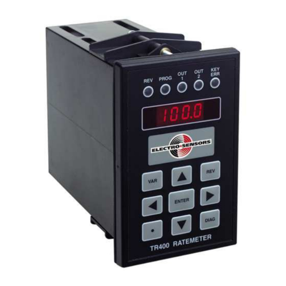
Page 26: Tr400 Parts And Functions
(9) keys. See Figures 9a and 9b; the letters in Figures 9a and 9b represent each part on the front panel of the TR400. The Parts and Functions table that follows describes the function of each the parts. - Page 27 ENTER DIAG TR400 RATEMETER Figure 9b: TR400 Front Panel Description Table 3: TR400 Panel Parts and Functions (continued) Part Function The OUT 2 LED will light when relay “2” is activated. Relay “2” is enabled by variable 13, and its set point value is entered in variable 10.
-
Page 28: Tr400 Set-Up Parameters
S4− − − − TR400 Set-Up Parameters TR400 set-up parameters Set-up The TR400 comes from the factory set for NPN open-collector operation. In most parameters applications, when using a standard Hall-Effect sensor with the model 255 disc, only a few variables need to be programmed. For example, RPM (Revolutions Per Minute) and PPR (Pulses Per Revolution): •... -
Page 29: Section 5
Section 5 TR400 Programming Introduction This section discusses information about programming the TR400. In this section These are the topics: Topic See Page Programmable variables How to select a variable and view its data Keypad keys used to access and program variables How to select and change a variable’s numerical value... -
Page 30: Programmable Variables
S5− − − − TR400 Programming Programmable variables Variables Table 4 describes the programmable variables for the TR400. Table 4: TR400 Programmable Variables Var # Variable Name Description See Page Default User Values Values Security Match Code This value is compared to the security code 0400 number, which is programmed in diagnostics. - Page 31 000.0 Response Time percent. The analog output changes with input frequency changes. Modbus Node Address the TR400 resides on the network Addendum 0001 Address Modbus Baud Rate 0 = 2400, 1 = 4800, 2 = 9600, 3 = 19200, 4 =...
- Page 32 S5− − − − TR400 Programming Programmable variables, continued Var # Variable Name Description See Page Default User Values Values Output 5 Value Holds the set-point value for output “5” in 0400 display units. Output 5 Delay Time The amount of time that the set-point condition 001.0...
-
Page 33: How To Select A Variable And View Its Data
Figure 11: TR400 Placed in Program Mode Displaying Variable 01 Note: The TR400 will remember the last variable selected and changed until the TR400 is powered Down and then Up. This will Reset the TR400 to display Pr01 (the first time you enter Program Mode after a power-up). - Page 34 S5− − − − TR400 Programming How to select a variable and view its data, continued To view the data for variable 01, do the following: Viewing variable data Step Action Press the ENTER key to go to the data-entry level; the display will show 1800, the (default value) for variable 01, Max RPM, with the 1’s digit...
-
Page 35: Keypad Keys Used To Access And Program Variables
RIGHT ARROW, UP ARROW, DOWN ARROW, DECIMAL, and ENTER keypad keys. The REV and DIAG keys are inactive when the TR400 is in Program Mode. Figure 14 shows only the keys used to program the variables. Table 5 describes the keys and their functions. -
Page 36: How To Select And Change A Variable's Numerical Value
Note: You can use the following 7-step procedure to select any variable, change its value, and save the results. Note: You can select a variable and change its value either when the TR400 is monitoring or when it is idle. - Page 37 S5− − − − TR400 Programming How to select and change a variable’s numerical value, continued To change the PPR from 8 to 16 for variable 02, press each key the number of times Changing the value shown in the three (3) steps below, while viewing the results on the display.
-
Page 38: Programming Rate And Signal Parameters
S5− − − − TR400 Programming Programming rate and signal parameters Programming Rate The TR400 has the ability to display rates as “Speed” or as Overview “Time in Process.” Variables 01, 02, 03, 23 and 24 are used to program the rate and signal parameters. -
Page 39: Programming The Display Operation
S5− − − − TR400 Programming Programming the display operation Overview Variables 04, 17, and 18 select the data to be displayed and the frequency at which it will be displayed. Variable 04, The Rate Function sets the display and input signal types as shown below. - Page 40 Variable 17, The Range Selection can be set to values from 2 to 9999. The default setting is 500, which should be suitable for most applications. If the TR400 display does not zero range selection out as desired, decrease the range selection value which will decrease the time for the display to read zero (0), but will increase the minimum speed that will appear on the display.
-
Page 41: Programming The Relay Outputs
S5− − − − TR400 Programming Programming the relay outputs Overview of the variables in a Start delay matrix as they Setpoint value pertain to the Delay time Setpoints On time Relay function Variables 13, 42 The Relay Output Function sets the function of the relay outputs and the direction &... - Page 42 Forward Only When the output activation-direction digit of variables 13, 42, 49 is Variables 13, 42, and 49 set to zero (0), the associated output set point is only valid when the TR400 activation recognizes the input signal as being in the forward direction (REV LED OFF).
- Page 43 S5− − − − TR400 Programming Programming the relay outputs, continued Output Delay Times are used to set the amount of time the set-point condition must Variables 08, 11, 37, 40, 44, exist before the output will respond. The default value for these variables is one (1) 47, relay second.
-
Page 44: Programming The Analog Output
Variables 15 and 16 can be set up for reverse direction or as a window, 200 − 800 Note: RPM. Variable 19, The variable sets the response time of the TR400's analog output from 0 to 100 percent. The TR400 will limit how much the analog output can change as the input analog output response time frequency changes, filtering the output. -
Page 45: Programming The Switch Inputs
The switch inputs are configured using variable 14. The switch inputs can be configured to Reset the outputs or freeze the display. For switch input wiring, see the TR400 Wiring & DIP Switches section. Caution When the digital input function is programmed as a Reset input and the switch input remains closed, the relay will never turn OFF regardless of the operating condition. -
Page 46: Programming The Display Features
S5− − − − TR400 Programming Programming the display features This variable configures how the display appears. Variable 26, Leading Zero The display appearance bit assignments are as shown below: Blanking and Segment Display Characters intensity Leading Zero blanking makes the leading zeros dark or not lit. -
Page 47: Section 6
TR400 Diagnostics Introduction Diagnostics are used to test the functionality of the TR400. When the DIAG key is pressed, the TR400 will display “dIAg,” and all of the LEDs except the KEY ERR LED will light. The LEDs will remain on until you exit Diagnostic Mode. -
Page 48: Keypad And Display Test
S6− − − − TR400 Diagnostics Keypad and display test Overview The keypad diagnostic tests the functionality of each key and bit position on the display. Keypad and To perform the keypad test, do the following: display test Step Action Press the DIAG key. -
Page 49: Relay Output Test
S6− − − − TR400 Diagnostics Relay output test Overview The Relay Output diagnostic tests the functionality of the relays. Relay output To test the relay outputs, do the following: test Step Action Press the DIAG key. Press the RIGHT ARROW key and the display will show the status of relay outputs 1, 3, 5, 7 and 2, 4, 6, 8. -
Page 50: Switch Input Test
Switch input test Overview The Switch Input diagnostic tests the TR400’s ability to recognize switch inputs tied to TB−1. When a closed switch is tied to TB−2, screw tap 1, 2, or 3, the corresponding bit position will toggle to “1.”... -
Page 51: Analog Output Calibration
S6− − − − TR400 Diagnostics Analog output calibration Overview The Analog Output diagnostic puts the TR400 into Pot Output Mode, which permits ∗ you to adjust the 4-20 mA 12-bit isolated, or the 0-10 Vdc output. The same hardware and procedure are used regardless of the option. There is a direct correlation between current/voltage and speed. - Page 52 S6− − − − TR400 Diagnostics Analog output calibration, continued Step Action Press the DOWN ARROW key and the display will appear, as shown in Figure 19. Display Characters Percent Symbol 00 – 99 Range Figure 19: 4− − − − 20 mA or 0− − − − 10 Vdc Output Display In Percent Turn the Offset Pot until the mA meter reads 4 mA or V meter reads 0 Vdc.
-
Page 53: Resetting The Variables
S6− − − − TR400 Diagnostics Resetting the variables Overview When necessary, the TR400’s variables can be reset to factory default, using the default function. See Figure 20. Resetting To Reset the variables, do the following: variables Step Action Press the DIAG key. -
Page 54: Setting And Changing The Security Code Number
Setting and changing the security code number Overview The TR400 can be programmed to prevent unauthorized changes to its operational variables by setting the keypad lockout function, using a security code number. There are three elements to enable or disable the keypad lockout function: variable 05 (selectable lockouts), variable 00 (security access number), and the location where you set up the security code number, which will be in Diagnostics. - Page 55 S6− − − − TR400 Diagnostics Setting and changing the security code number, continued Setting security To set the security code number, do the following: Step Action Determine which keys you want to lock out, using variable 05. The default is 0011, which locks out the DIAG key and prevents changes to operational variables, except variable 00.
-
Page 56: System Slowdown Test
Activating the test on the TR400 slowly scales down the actual input frequency to ramp down the display and trigger the relays, (simulating a real slowdown while running at normal speed). -
Page 57: Viewing Shaft Deviation
S6− − − − TR400 Diagnostics Viewing shaft deviation Overview The TR400 will calculate and display the deviation for you while the shaft is running at a stable speed. The shaft must be rotating at a steady speed before the deviation is going to How to View be checked. -
Page 58: Clearing The Lrc Code
S6− − − − TR400 Diagnostics Clearing the LRC code LRC on the display is due to the EEPROM memory corruption. This is typically caused by a large power disturbance. Normally all that is necessary is the unit will have to be reset, and the values in the variables re-entered. -
Page 59: Tr400 Specifications
Appendix A: TR400 Specifications Power Description • 115 Vac, 6VA @ 50/60 Hz, requires external fuse 1/16 amp slow- Input Power blow • 230 Vac, 6VA @ 50/60 Hz, requires external fuse 1/32 amp slow- blow • 10-30 Vdc requires external fuse 2 amp slow- blow... - Page 60 TR400 Specifications Operational Values Description Accuracy Display and relays: 0.01 percent +/- 1digit Analog: .1% linearity Frequency range .01 Hz to 4Khz Response Time Minimum 0.02 seconds Default 500 − 1, can be programmed from 9999 − 1 Control Range •...
-
Page 61: Index
11, 16 signal type, 33, 34 Installation wiring, 16 panel cutout dimensions, 7 wiring caution, 16 unpacking TR400, 6 AC Power 115 Vac, 12, 53 230 Vac, 12, 53 fuse, 12, 53 Keypad Lockout, 48 Analog Output, 11, 13, 45, 46... - Page 62 17 range selection, 34 Sensors 18 display update interval, 34 electrical connections, 17 19 analog output response time, 38 electro-sensors settings, 17 22 analog output cutoff, 38 Set Point 23 Pulses to Average, 32 delay times, 36, 37 24 Averaging Window, 32...
- Page 63 Index 26 Leading zero blanking and LED 56 relays 7 & 8 output function, 35 intensity, 40 accessing and programming, 29 36 relay output 3 setpoint, 36 selecting and changing values, 30, 31 37 relay output 3 delay time, 37 selecting and viewing, 27, 28 38 relay output 3 on time, 37 Viewing shaft deviation, 51...
- Page 64 Index Rev G...
- Page 66 Electro-Sensors®, Inc. 6111 Blue Circle Drive Minnetonka, MN 55343-9108 Contact us at: Local: 952-930-0100 National: 1-800-328-6170 Fax: 952-930-0130 Web: www.electro-sensors.com Sales www.sales@electro-sensors.com Support: www.tech@electro-sensors.com...
Need help?
Do you have a question about the TR400 and is the answer not in the manual?
Questions and answers