Table of Contents
Advertisement
Quick Links
Advertisement
Table of Contents

Summary of Contents for HMS Networks Ixxat CANnector Log
- Page 1 CANnector Log USER MANUAL 4.01.0091.21000 1.1 en-US ENGLISH...
- Page 2 HMS Networks reserves the right to modify its products in line with its policy of continuous product development. The information in this document shall therefore not be construed as a commitment on the part of HMS Networks and is subject to change without notice. HMS Networks makes no commitment to update or keep current the information in this document.
-
Page 3: Table Of Contents
Table of Contents Page User Guide ........................... 3 Target Audience.......................3 Related Documents ......................3 Document History ......................3 Trademark Information .....................3 Conventions........................4 Safety Instructions ......................5 Information on EMC ......................5 General Safety Instructions ....................5 Intended Use........................5 Scope of Delivery ........................ 5 Product Description ......................6 Features .........................6 Software for Configuration and Visualization ................6 Installation........................... - Page 4 Configuration........................13 Pre-Configured CAN Logging Configurations................ 13 7.1.1 Selecting a Configuration with Different Baud Rate............13 7.1.2 Setting a Specific Baud Rate ................... 14 Creating New Configurations.................... 18 7.2.1 Creating a Configuration without Bus Description File ............ 18 7.2.2 Using Messages as Trigger ..................21 7.2.3 Creating a Configuration with Bus Description File............
-
Page 5: User Guide
User Guide 3 (36) User Guide Please read the manual carefully. Make sure you fully understand the manual before using the product. Target Audience This manual addresses trained personnel who are familiar with CAN, CAN FD, LIN, and the applicable national standards. The contents of the manual must be made available to any person authorized to use or operate the product. -
Page 6: Conventions
User Guide 4 (36) Conventions Instructions and results are structured as follows: ► instruction 1 ► instruction 2 → result 1 → result 2 Lists are structured as follows: • item 1 • item 2 Bold typeface indicates interactive parts such as connectors and switches on the hardware, or menus and buttons in a graphical user interface. -
Page 7: Safety Instructions
Safety Instructions 5 (36) Safety Instructions Information on EMC Risk of interference to radio and television if used in office or home environment! The product is a class A device. Use exclusively included accessories or HMS accessories that are intended for use with the device. -
Page 8: Product Description
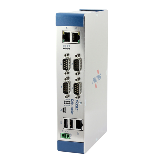
Product Description 6 (36) Product Description With the CANnector Log the communication of the connected busses can be logged. The four provided basic logging configurations, that initializes all 6 CAN interfaces with 125 Kbit/s, 250 Kbit/s, 500 Kbit/s, or 1000 Kbit/s log all received data in csv format. With the ACT configuration tool configurations can be created, that allow for example to log individual messages and individual signals, and to define trigger messages. -
Page 9: Installation
Installation 7 (36) Installation Installing the Software To connect the CANnector Log to a PC via USB a driver is needed. With installation of the configuration tool ACT the driver is automatically installed. The ACT tool can be downloaded on www.ixxat.com. ►... -
Page 10: Installing The Adhesive Feet
Installation 8 (36) 5.2.2 Installing the Adhesive Feet Stick the adhesive feet to the bottom of the device. ► ► Place the CANnector on an even surface. ► Make sure, that the venting slots are not covered and ensure adequate air circulation (recommended mounting distance: 2 cm distance to venting slots). -
Page 11: Reading The Log Data
Reading the Log Data 9 (36) Reading the Log Data The log data can be read in different ways: • manually from the USB memory storage device (see Reading the Log Data Manually, p. • in the dashboard (see Reading the Log Data in the Dashboard, p. •... -
Page 12: Reading The Log Data Manually
Reading the Log Data 10 (36) Reading the Log Data Manually Disconnect the CANnector Log from power supply. ► Unplug the USB memory storage device. ► ► To read the logging data, plug the USB memory storage device in a PC. Reading the Log Data in the Dashboard With the WiFI extension for the CANnector Log the log data can be read wireless via smartphone or tablet. -
Page 13: Reading The Log Data With Ixadmin
Reading the Log Data 11 (36) Select USB Stick (2). ► → Log files are shown. ► If current log file is not shown in the list, click button Refresh (3) to update the list. ► To download a log file, click on the desired log file. To start the logging again, in configuration tree select State, select the desired application ►... - Page 14 Reading the Log Data 12 (36) ► Click button OK. → Connection to CANnector is established. Fig. 7 IxAdmin log files ► Click button Stop (1) to stop the logger configuration. Open tab Mass Storage (2). ► → Log data that is stored on USB memory storage device is shown (3). ►...
-
Page 15: Configuration
Configuration 13 (36) Configuration By default the CANnector Log starts with a CAN logging configuration that initializes all 6 CAN interfaces with 250 Kbit/s and logs all received messages in csv format. To change the baud rate of all CAN interfaces to 125 Kbit/s, 500 Kbit/s, or 1000 Kbit/ another pre-configured configuration can be selected with the dashboard (see Selecting a Configuration with Different Baud Rate, p. -
Page 16: Setting A Specific Baud Rate
Configuration 14 (36) 7.1.2 Setting a Specific Baud Rate With IxAdmin it is possible to set an individual baud rate for each CAN bus or a specific baud rate (e.g. 666 kBit/s) without creating a new configuration. Make sure, that the required software is installed (see Installing the Software, p. - Page 17 Configuration 15 (36) Click on button Open folder (1). ► ► Select a pre-configured basic configuration (sdcfg file) and click button Open. The sdcfg file is the download project file of a configuration, that contains all links to all files that are required for one configuration.
- Page 18 Configuration 16 (36) Fig. 12 IxAdmin Edit Baud rate of CAN controller ► Select the desired baud rate in drop-down menu Standard Timing (1). To enable CAN FD with CAN 5 and CAN 6, activate Enable Flexible Data Rate (2) to be able ►...
- Page 19 Configuration 17 (36) Fig. 13 Save application In window Add/Remove application save the configuration with button Save (1). ► ► In field Control (2) define the memory the configuration is downloaded to: – Select Flash for the non-volatile memory of the target device. Configurations which are downloaded to the Flash memory, are automatically started at the next power-on of the device.
-
Page 20: Creating New Configurations
Configuration 18 (36) Creating New Configurations To use more functions of the CANnector Log, logger configurations can be created with the freeware ACT tool. Basically two logger configuration types can be created: logger without bus description files (log messages) and logger with bus description files (log individual signals). For example the following functions can be used with the CANnector Log: •... - Page 21 Configuration 19 (36) Fig. 15 ACT wizard Select target platform Ixxat CANnector S and click button Next. ► The CANnector Log is based on the CANnector S. Fig. 16 Bus configuration ► To set the baud rate of the CAN busses, click button and select the desired baud rate.
- Page 22 Configuration 20 (36) Fig. 17 Logger configuration window ► Select the desired CAN bus as source (1) and the tab Logger (5) as destination. ► In Source (1) open tab Message (2). In drop-down list Map Subject select Message (6). ►...
-
Page 23: Using Messages As Trigger
Configuration 21 (36) ► To define an individual message: ► Right-click in source field (2) and select New Message in the context menu. → Window to define a message is opened. Fig. 18 Configure new message Create the desired message and click button OK. ►... - Page 24 Configuration 22 (36) Select tab Trigger (4) as destination. ► ► Drag and drop the desired trigger message from source (1) to destination trigger (4). → Mapped message is the input signal (2). ► To define the logic, right-click in the trigger window. →...
-
Page 25: Creating A Configuration With Bus Description File
Configuration 23 (36) ► To add the trigger logic to the logger configuration, open the tab Logger and select the created trigger signals in fields Start Trigger (1) and Stop Trigger (2). Fig. 21 Add trigger logic to logger configuration To start the logging before the trigger, define a PreTrigger time. - Page 26 Configuration 24 (36) ► Select the project template Logger with Bus Description and click button Next. Fig. 23 ACT wizard ► Select target platform Ixxat CANnector S and click button Next. The CANnector Log is based on the CANnector S. ►...
- Page 27 Configuration 25 (36) ► Click button Next. → Window to configure the logger is opened. Fig. 25 Logger configuration window ► Select the desired CAN bus as source (1) and the tab Logger (4) as destination. In source open tab ECUs (2). ►...
-
Page 28: Using Signals As Trigger
Configuration 26 (36) ► To load the logger configuration to the device, open menu Build and select Download. → IxAdmin is started. ► Load the logger configuration with IxAdmin to the CANnector Log (see Loading Configurations to the Device, p. 28). - Page 29 Configuration 27 (36) Connect the logic with drag and drop (3). ► As minimum a threshold and a trigger function block are needed (the threshold is given on physical level). To stop the logging after a certain time, for example, add a timer and a further trigger. The various function blocks can be combined freely.
-
Page 30: Loading Configurations To The Device
Configuration 28 (36) 7.2.5 Loading Configurations to the Device Make sure, that the required software is installed (see Installing the Software, p. 7) and that ► the CANnector Log is connected (see Connecting the Device, p. Start IxAdmin. ► → Window Connect Device is opened. -
Page 31: Configuring Further Functions
Configuration 29 (36) ► Open menu Device and select Add/Remove Application. Fig. 30 IxAdmin CANnector configuration Click button Open folder (1). ► Select the created configuration (sdcfg file) and click button Open. ► → Selected configuration is opened. ► Save the configuration with button Save (1). ►... - Page 32 Configuration 30 (36) MatLab Possibility to calculate signals with a MatLab/Simulink models Simulink model that runs on the CANnector OPC-UA Standardized protocol for data exchange with a cloud System System bus Contains all status signals of all used bus systems, e.g. CAN bus status Usercode C code extension of the configuration Possibility to extend the configurations with...
-
Page 33: Technical Data
Technical Data 31 (36) Technical Data Basic Unit Dimensions (L x W x H) 196 x 113 x 43 mm (without DIN rail bracket and device feet) Weight 790 g Operating temperature -40 °C to +80 °C Storage temperature -40 °C to +85 °C 6-36 V DC Power supply Current consumption... -
Page 34: Support/Return Hardware
32 (36) Support/Return Hardware Support/Return Hardware Support ► For problems or support with the product request support at www.ixxat.com/support. ► If required use support phone contacts on www.ixxat.com. Return Hardware Fill in the form for warranty claims and repair on www.ixxat.com/support/product-returns. ►... -
Page 35: A Regulatory Compliance
Appendix A: Regulatory Compliance 33 (36) Regulatory Compliance EMC Compliance (CE) The product is in compliance with the Electromagnetic Compatibility Directive. More information and the Declaration of Conformity is found at www.ixxat.com. Disposal and recycling You must dispose of this product properly according to local laws and regulations. Because this product contains electronic components, it must be disposed of separately from household waste. -
Page 36: B Open Source Software
34 (36) Open Source Software The software of the Ixxat CANnector Log contains software components that are licensed as Free Software or Open Source Software by the rights holders. The corresponding licenses are available on the support area of the CANnector Log on www.ixxat.com. (Included in Firmware Download Package as well as included in Offline Help Package). - Page 37 This page intentionally left blank...
- Page 38 last page © 2020 HMS Industrial Networks Box 4126 300 04 Halmstad, Sweden info@hms.se 4.01.0091.21000 1.1 en-US / 2020-11-17 / 20670...
Need help?
Do you have a question about the Ixxat CANnector Log and is the answer not in the manual?
Questions and answers