
Summary of Contents for Dohrmann Enterprises DE-1008.5
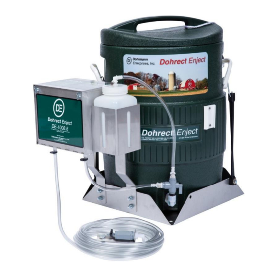
- Page 1 Dohrmann Enterprises, Inc. Owner’s Manual DE-1008.5(-X2) Dohrect Enject System MY2019+ REV: 03-2021...
-
Page 3: Table Of Contents
Pumping Tube Selection, Installation & 17-18 Replacement Operation & Calibration 19, 21 Calibration Charts Troubleshooting 22-24 DE-1008.5 Parts Breakdown 25-29 For additional Calibration, Maintenance and Troubleshooting help, please give us a call or check out our videos, which can be found at: www.DohrmannEnterprises.com/videos. -
Page 4: Warranty Information
WARRANTY Dohrmann Enterprises, Inc. will repair or replace any applicator part(s) that are found to be defective within one year from the original date of purchase, except for wear parts (pumping tubes). Defective parts must be returned to Dohrmann Enterprises, Inc. within 30 days of failure with shipping and handling fees prepaid. -
Page 5: For Safe Operation
FOR SAFE OPERATION 1. Read and follow all instructions before attempting to install or start this equipment. 2. Do not attempt to apply any chemical through equipment until you read and understand chemical safety information and application rates. 3. Before applying a chemical, read product labels. 4. -
Page 6: Assembly & Installation
1. Your DE-1008.5 Dohrect Enject System is shipped assembled. Carefully remove the foam top packaging and lift the DE-1008.5 unit out of the box. Save the original box and packaging should the applicator need to be shipped in the future. - Page 7 (located on the left side of the cooler valve assembly) and inserting the fitting until it CLICKS. • If you are installing a DE-1008.5, please skip the directions for the manifold installation and proceed to WIRING on Page 9. DE-1008.5-X2...
-
Page 8: Manifold Installation (De-1008.5X2)
1008.5-MAN TANK MANIFOLD INSTALLATION 1. Locate the area you would like to install the manifold. 2. Before installation, give some consideration to who will be opening and closing the valves in the field. a. If it is the chopper operator, mount the manifold either to the side of the cab, on the fender, or on a baseplate where the operator can reach it. -
Page 9: Wiring
WIRING Your DE-1008.5 is shipped with the power cord assembly, Part #364-1008.5, connected to the SP-2L Control. The power cord assembly has two sections. • The first section, Part #364A, will be installed 364-1008.5 from your power supply to the SP-2L Control. - Page 10 WIRING Part #364A has bare wires and fuse holder. This end will be 170017 connected to your 12 Volt DC power source. You may need to change the terminals to mate up with your power source. There are additional connections found in the electrical pack, Part #170017. •...
-
Page 11: Header Switch Wiring
• Your chopper must be equipped with this option and you must have the electrical connections to mate up to the chopper’s plug. Dohrmann Enterprises, Inc. does not stock the factory plugs for header switch connections. Header switch adapters can be purchased from your local implement dealer. -
Page 12: Plumbing
PLUMBING IMPORTANT: There are NO NOZZLES or nozzle fittings shipped with your Dohrect Enject System. These units are designed to work without nozzles. Due to the low rates per ton, applicator through a nozzle would have a high plugging risk due to the small orifice sized required. -
Page 13: Flowmeter Plumbing
FLOWMETER PLUMBING The FM-1008.5-LED is shipped with a 20’ length of ¼” ID X 3/8” OD hose, Part #451-20, for the pump output. This hose will route to the FM-1008.5-LED Flowmeter and continue on from the FM-1008.5-LED Flowmeter to the cutter head. 1. - Page 14 Find your desired discharge location. It should either be in front of the feed rolls, or behind the feed rolls, but in front of the knives. Coverage tests that Dohrmann Enterprises, Inc. has been involved in, or contributed equipment to, placed the discharge in one of these locations with successful results.
-
Page 15: Discharge Bracket, Placement
DISCHARGE BRACKET PLACEMENT EXAMPLES PULL-TYPE CLAAS JOHN DEERE KRONE NEW HOLLAND... -
Page 16: Calibration
DE-1008.5 CALIBRATION & PUMP TUBE SELECTION PUMP TUBE SELECTION & CALIBRATION There are two color coded pump tubes shipped with your applicator – Red and Blue – as indicated by the zip ties on either end. Use the instructions below to determine which pump tube will work best with your harvest rate and product concentration (mix rate). -
Page 17: Pumping Tube Selection, Installation
DE-1008.5 PUMP TUBE INSTALLATION AND REPLACEMENT Even if the cooler is empty, a good habit to get into is start by turning the cooler valve off. When off, the valve handle will either be DRAWING FROM facing out towards you,... - Page 18 DE-1008.5 PUMP TUBE INSTALLATION AND REPLACEMENT Remove the pump tube. Install the new pump tube by pressing in the silver tab on one of the fittings on the bottom of the enclosure. Push end of the tube into the hole until you hear it CLICK into place.
-
Page 19: Operation & Calibration
OPERATION & CALIBRATION SP-2L CONTROL The SP-2L Control contains the system’s master on/off switch, along with a dial to control the speed of the pump. • ON/OFF: If your system is wired through a header switch you can turn the unit on and allow the header switch to turn the control on and off throughout the day. -
Page 20: Calibration Charts
CALIBRATION CHARTS The Calibration Charts below are to provide you with the amount of total solution that you need to apply based upon your mix rate and tonnage per minute harvested. Please note that you may need to change your mix rate if your harvest rate drops below the lowest output of the pump. - Page 21 This will prevent the lines and the flowmeter from freezing and/or cracking. GENERAL MAINTENANCE The DE-1008.5 Applicator has only one wear part. This part is the Pumping Tube. The Pumping Tube needs to be replaced as needed or annually, whichever comes first. If the Pumping Tube wears out, the motor will still run, but it will not pump any product, or will have a significant reduction in output.
-
Page 22: Troubleshooting
SYSTEM TROUBLESHOOTING Pump Does Not Pump • Does the motor run? o No – Jump to “Motor Does Not Run” on Page 23 o Yes – Continue On ▪ When was the pumping tube last replaced? Pumping tubes should be replaced annually, or more often depending on use. - Page 23 Motor Does Not Run • When the switch is on, does the LED light on the control light up? o No – Continue to the next step. o Yes – Continue on ▪ Check wiring for any nicks, frays, and that you have good clean connections.
- Page 24 o Verify that there is power going to the control. ▪ Verify the input lead is connected to a power supply. ▪ Check to make sure the fuse is not blown. ▪ Check wiring for any nicks, frays, and that you have good clean connections.
-
Page 25: De-1008.5 Parts Breakdown
1008.5-PT-RED 1008.5 Series Pumping Tube - RED 170017 Electrical Pack for Assembly Kits 170018 DE-1008.5 Mounting Hardware Bag DE-1008.5 – 11” Pump Hose – Hose 170021 and fitting connecting pump to cooler ¼” HB Quick Connect Straight LT14HBSTR 170026 DE-1008.5 Check Valve Assembly with 20’... - Page 26 DE-1008.5 – 35’ Complete Power 364-1008.5 Cord Assembly BREAKDOWN OF 364-1008.5 DE-1008.5 – 15’ Power Cord – From 364A Power Source to Controller DE-1008.5 – 20’ Power Cord – From 364C Controller to Pump Flowmeter Assembly w/LED Light – FM-1008.5-LED Dohrect Enject Series –...
- Page 27 BREAKDOWN OF CVA-130-QC ¼” MPT X Quick Connect Socket LT14MPTQC ¼” Street Elbow ½” X ¼” Reducer Bushing ¼” X ¼” Close Nipple ½” X ½” FPT Coupler ¼” 3-Way Valve ¼” Suction Strainer (Inside Cooler) 130/GSK Gasket/Washer Assembly for Cooler ½”...
- Page 28 Pump Enclosure – DE-1008.5 1008.5-ENC Not pictured Dohrect Enject Series (Does not include hardware) 108.5 DE-1008.5 Pump (Does NOT include pumping tubes) Pump Mount Bracket (13” w/Offset 177-OSB-SS Not pictured Bend (Does not include hardware) ¼” HB Panel Mount Quick Connect...
- Page 29 Flush Bottle Assembly – For FLB32QC DE-1008.5 Series Dohrect Enject System BREAKDOWN OF FLB32QC DE-1008.5 – 15” Flush Bottle Hose 170020 FLB32QC-NH/NHF Flush Bottle Assembly for DE-1008.5 Series (Does not include hose or hose fittings) ¼” HB Quick Connect Elbow LT14HBEL Owner’s Manual for DE-1008.5...
Need help?
Do you have a question about the DE-1008.5 and is the answer not in the manual?
Questions and answers