Advertisement
Quick Links
W
W
D
e
D
e
I
n
s
I
n
s
E
a
E
a
May 2012, Rev -
Wireless Energy Demonstration Kit
i
r
e
l
e
s
s
i
r
e
l
e
s
s
m
o
n
s
t
m
o
n
s
t
t
r
u
c
t
i
o
t
r
u
c
t
i
o
s
t
e
r
n
V
o
l
t
a
g
e
s
t
e
r
n
V
o
l
t
a
g
E
n
e
r
E
n
e
r
r
a
t
i
o
n
r
a
t
i
o
n
n
M
a
n
n
M
a
n
R
e
s
e
a
r
c
h
,
e
R
e
s
e
a
r
c
h
,
− 1 −
http://www.EasternVoltageResearch.com
Wireless Energy Demonstration Kit
g
y
g
y
K
i
t
K
i
t
u
a
l
u
a
l
L
L
C
L
L
C
Advertisement

Summary of Contents for Eastern Voltage Research Wireless Energy Demonstration Kit
- Page 1 Wireless Energy Demonstration Kit − 1 − May 2012, Rev - http://www.EasternVoltageResearch.com Wireless Energy Demonstration Kit...
- Page 2 Wireless Energy Demonstration Kit AGE DISCLAIMER THIS KIT IS AN ADVANCED, HIGH POWER SOLID STATE POWER DEVICE. IT IS INTENDED FOR USE FOR INDIVIDUALS OVER 18 YEARS OF AGE WITH PROPER KNOWLEDGE EXPERIENCE, AS WELL AS FAMILIARITY WITH LINE VOLTAGE POWER CIRCUITS.
- Page 3 Wireless Energy Demonstration Kit SAFETY AND EQUIPMENT HAZARDS PLEASE BE SURE TO READ AND UNDERSTAND SAFETY EQUIPMENT RELATED HAZARDS AND WARNINGS BEFORE BUILDING AND OPERATING YOUR KIT. THE PURPOSE OF THESE WARNINGS IS NOT TO SCARE YOU, KEEP WELL INFORMED TO WHAT HAZARDS MAY APPLY FOR YOUR PARTICULAR KIT.
- Page 4 Wireless Energy Demonstration Kit VARIAC WARNING DO NOT USE A VARIAC WITH THIS PRODUCT. THIS PRODUCT REQUIRES POWER THROUGH AN ISOLATED TRANSFORMER (SUCH AS THE ONES PROVIDED IN THE KITS). A VARIAC IS NOT ISOLATED AND USING A VARIAC WITH...
- Page 5 Wireless Energy Demonstration Kit ELECTRICAL HAZARD This circuit utilizes dangerous line voltages up to 115VAC. Failure to handle this circuit in a safe manner may result in serious injury or death! POWER SEMICONDUCTOR HAZARD This is a solid state power device. Components may fail explosively at any time and eject high velocity projectiles.
-
Page 6: Fire Hazard
Wireless Energy Demonstration Kit FIRE HAZARD Due to high power dissipations of the various semiconductors devices attached to the heatsink, the heatsink may become extremely hot, especially during periods of continuous operation. Please ensure the heatsink is not installed on or near any flammable material and that a cooling fan is ALWAYS used during operation. - Page 7 Wireless Energy Demonstration Kit electrical path through your heart providing you accidentally make contact with live voltage. Wear footwear with non-conductive (rubber) soles. Do NOT work on line powered or high voltage equipment in barefeet. Always wear eye protection. Power semiconductor devices, and capacitors do have the potential to explode unexpectedly and project sharp fragments across the room.
- Page 8 Wireless Energy Demonstration Kit SAFETY GUIDELINES – HIGH TEMPERATURE COMPONENTS Power semiconductors may be extremely hot. NEVER touch any semiconductors during operation or after use. Always allow proper time for components to cool down prior to handling them. The extruded aluminum heatsink will be extremely hot during and after use until it cools down to ambient temperature.
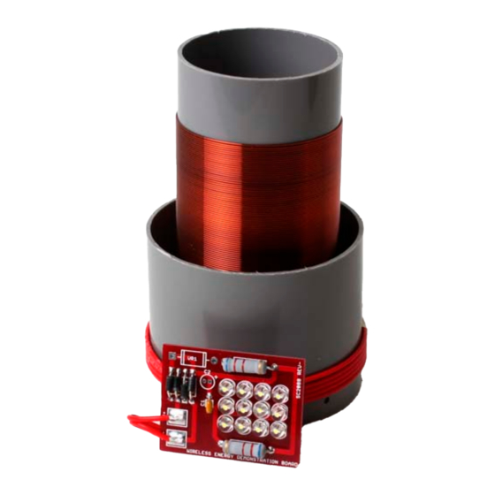
- Page 9 Wireless Energy Demonstration Kit Introduction to the Wireless Energy Demonstration Kit Thank you for purchasing the Wireless Energy Demonstration Kit. This kit is perfect to demonstrate the principle of wireless energy transfer and is designed to be used in conjunction with our Class-E Audio Modulated Tesla Coil kits.
- Page 10 Wireless Energy Demonstration Kit Kit Building Tips A good soldering technique is key! Let your soldering iron tip gently heat both the wires and pads simultaneously. Apply solder to the wire and the pad when the pad is hot enough to melt the solder. The finished joint should appear like a small shiny drop of water on paper, somewhat soaked in.
- Page 11 Wireless Energy Demonstration Kit Wireless Energy Demonstration Kit Parts List RESISTORS 6.2k ohm Resistor, 2W (blue-red-red), R1,R2 CAPACITORS 1uF Ceramic Capacitor (marked M39014/02-1407 or BC105), C1 DIODES LED, White, D1,D2,D3,D4,D5,D6,D7,D8,D9,D10,D11,D12 STPS1150 Diode (marked STPS1150), CR1,CR2,CR3,CR4 ...
- Page 12 Wireless Energy Demonstration Kit Wireless Energy Board - Component Layout Diagram − 12 − May 2012, Rev - http://www.EasternVoltageResearch.com Wireless Energy Demonstration Kit...
- Page 13 Wireless Energy Demonstration Kit KIT Building Instructions Now we will begin building the kit. There are just a few more important things to know before we install the first components. For each component, the word “install” always means the following: Pick the correct value to start with.
- Page 14 Wireless Energy Demonstration Kit 7. Install C1, 1uF capacitor (marking M39014/02/1407 or BC105) 8. Install D1, LED. The short lead of the diode is the cathode and will install into the square pad on the PCB board. ...
- Page 15 Wireless Energy Demonstration Kit secondary RF ground to the included ground wire and PCB board. Begin winding the secondary at the locations shown in the figure below. Continue winding the secondary, ensuring each wind is neat and tightly together with adjacent windings, for the entire length as indicated in the figure below.
- Page 16 Wireless Energy Demonstration Kit 21. Form the top wire of the secondary into a discharge electrode as shown in the figure above. For initial tuning, is extremely important that the wirelength is precisely the length as shown in the figure above.
- Page 17 25. Attach the included black ground wire to the IN- terminal of the PCB board. This wire will be attached to EARTH ground for the safety reasons. Congratulations! You have just completed your Wireless Energy Demonstration kit. Please take a few moments to look over the board and ensure that all the components are installed properly with the correct orientation.
- Page 18 Wireless Energy Demonstration Kit Set-up and Testing Okay, so lets begin! RECOMMENDED TEST EQUIPMENT, NOT SUPPLIED None required Please be sure to wear safety glasses when testing and operating the Wireless Energy Demonstration Kit 1. Attach the black ground wire to any EARTH ground that is readily available as shown in the figure below.
- Page 19 Wireless Energy Demonstration Kit − 19 − May 2012, Rev - http://www.EasternVoltageResearch.com Wireless Energy Demonstration Kit...
- Page 20 1 ft. to the Class-E Tesla Resonator. Doing so may couple excessive energy into the wireless demonstration PCB board and overvoltage some of the devices on the board. Congratulations! Your Wireless Energy Demonstration Kit is now completed and operational. − 20 − May 2012, Rev - http://www.EasternVoltageResearch.com...
- Page 21 Wireless Energy Demonstration Kit Counterpoise Ground Arrangement If you wish to operate this unit without the connecting ground wire, you may wish to employ a counterpoise type grounding arrangement as shown in the figure below. We recommend a small metallic plate (copper or aluminum is ideal) with minimum dimensions of 4”...
- Page 22 Eastern Voltage Research, LLC Technical Support support@easternvoltageresearch.com Thanks again from the people here at Eastern Voltage Research. Terms and Conditions of Sale Before opening or assembling your kit, please read and review the latest Terms and Conditions of Sale on our website at the following link: http://www.easternvoltageresearch.com/terms.html...
Need help?
Do you have a question about the Wireless Energy Demonstration Kit and is the answer not in the manual?
Questions and answers