
Subscribe to Our Youtube Channel
Related Manuals for Woods ALITEC CP16BH

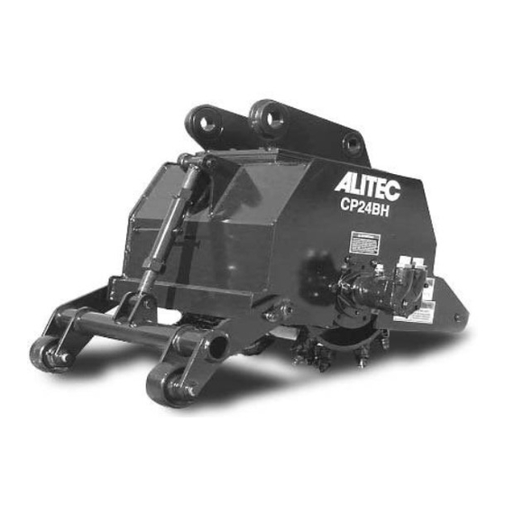
Summary of Contents for Woods ALITEC CP16BH
- Page 1 BACKHOE COLD PLANER CP16BH CP18BH CP24BH Effective Serial Numbers: CP18BH 220130900 CP24BH 200101596 Tested. Proven. Unbeatable.
-
Page 2: Introduction
Operator’s Manual. If using the mail-in form, the dealer is to return the prepaid postage portion to Woods, give one copy to the customer, and retain one copy. Failure to register the product does not diminish customer’s warranty rights. -
Page 3: Table Of Contents
TABLE OF CONTENTS INTRODUCTION ..........2 GENERAL INFORMATION . -
Page 4: General Information
GENERAL INFORMATION The purpose of this manual is to assist you in operating The illustrations and data used in this manual were cur- and maintaining your backhoe cold planer. Read it care- rent at the time of printing but, due to possible inline fully. -
Page 5: Safety Rules
SAFETY RULES ATTENTION! BECOME ALERT! YOUR SAFETY IS INVOLVED! must be surgically removed as soon as possible by Safety is a primary concern in the design and a doctor familiar with this form of injury or gan- manufacture of our products. Unfortunately, our grene, serious injury, or death will result. - Page 6 SAFETY RULES ATTENTION! BECOME ALERT! YOUR SAFETY IS INVOLVED! Never direct discharge toward people, animals, (Safety Rules continued from previous page) or property. Be sure attachment is properly secured, adjusted, and in good operating condition. Coupler Do not operate equipment while under the influ- lockpins must be fully extended and properly ence of alcohol or drugs.
- Page 7 SAFETY RULES ATTENTION! BECOME ALERT! YOUR SAFETY IS INVOLVED! When removing the flag pins, be sure to support (Safety Rules continued from previous page) the depth arm to prevent hands and feet from being Leak down or failure of mechanical or hydraulic crushed.
-
Page 8: Safety Decals
Replacement safety decals can be IG -PRESSURE YDRAULIC OIL LEAKS CAN PENETRATE SKIN RESULTING IN SERIOUS INJURY, GANGRENE OR DEAT . ordered free from your Woods dealer. To locate your nearest dealer, check the Check for leaks with cardboard; never use hand. -
Page 9: Operation 9
OPERATION ___ Check that hoses are not twisted, bent sharply, kinked, frayed or pulled tight. Replace any WARNING damaged hoses immediately. ___ Make sure power unit ROPS and seat belt are Safety instructions are important! Read all in good condition. Keep seat belt securely fas- attachment and power unit manuals;... - Page 10 NOTICE Operating Planer 1. Adjust the planer to desired cutting depth by ■ Keep the planer drum close to the ground. adjusting the depth jack (1) as shown in Figure 2. Avoid swinging the boom from side to side while planing as this may produce excessive drum wear 2.
-
Page 11: Troubleshooting 11
TROUBLESHOOTING PROBLEM POSSIBLE CAUSE SOLUTION Bucket function adjustment is Both primary and secondary Remove the secondary bucket pin required to control the planer bucket pins are installed between while planing to allow the planer to attitude. the planer and backhoe boom. freely swing about the primary pin. -
Page 12: Service
SERVICE Drum Removal 1. Support the planer with a hoist so the drum just touches the ground. 2. Remove three deadshaft bolts (1) as shown in Figure 4. The top bolt has a weld nut on the inside, so it is unnecessary to hold this nut with a wrench. Figure 6. - Page 13 2. Insert the motor into the planetary (1) as shown in Figure 10. Install two 1/2" –13 bolts (2), two 1/2" lock washers (3), and two 1/2" flat washers (4). 3. Torque to 90 lbs-ft. (122 N-m). Figure 8. Planetary Removal 1.
- Page 14 Figure 11. 4. Turn the drum over as shown in Figure 12. Install the planetary / motor assembly (8). Figure 13. 5. Install nine 9/16" –18 nuts (6) and nine 9/16" flat 9. Apply a thin coat of anti-seize grease to a portion of washers (7).
- Page 15 2. Remove the lower depth jack pin (2) 3. Remove two 1/2" bolts (3) from the flag pins (6). 4. Remove two flag pins (6). Figure 15. 12. Install four 5/8" –11 bolts (13) and four 5/8" flat washers (14) through the side plate and into the planetary as shown in Figure 16.
- Page 16 WARNING Always wear relatively tight and belted clothing to avoid getting caught in moving parts. Wear sturdy, rough-soled work shoes and protective equipment for eyes, hair, hands, hearing, and head; and respirator or filter mask where appropriate. Pick Installation 1. Insert the pick tool (1) into the slot on the pick (2) as shown in Figure 20.
- Page 17 NOTICE Deadshaft Bearing Lubrication To grease deadshaft bearing, set planer to zero depth ■ When transporting the planer, make sure the and rotate drum until grease zerk (3) is facing down as drum does not contact the ground as this may shown in Figure 21.
-
Page 18: Assemblies & Parts Lists
DRUM ASSEMBLY PART DESCRIPTION PART DESCRIPTION 104247 Stud, 1/2 - 13 x 1/2 - 20 x 2.50 1024801 50 Pick, Asphalt -or- 1024802 * Pick removal tool (for 1024801) B1050C 50 Pick, Concrete M0007 * Pick removal tool (for B1050A, 102670416 16"Drum assembly w/ picks -or- B1050S, B1050C) - Page 19 Bushing, CPBH CAT 2 S0100902 Bushing, CPBH 105876 Attach weld CAT416C -or- 105945 Attach weld CAT416D NOTE: Attachment brackets are available for other host machines. Please contact your local Woods dealer for details. (Rev. 5/31/2007) Parts 19 MCPBH-B (Rev. 4/20/2007)
- Page 20 BASE ASSEMBLY HC412 Motor Shown PART DESCRIPTION PART DESCRIPTION 101607724 24" Drum assembly with picks 100594 Wheel assembly (CP24) 101979 Deadshaft weldment, Triangle F1051 Fitting, 16 OM x 12 FLM ST 105818 Pin, Flag 1.25 x 2.625 (HC412) -or- 105867 Chassis weldment (CP16) F1006 Fitting, 12 OM x 12 FLM ST...
- Page 21 DECAL PLACEMENT PART DESCRIPTION PART DESCRIPTION D0193 Decal, Rotating drum D0042 Decal, Planetary oil D0404 Decal, Read Owner’s manual D0298 Decal, CP18BH -or- D0195 Decal, Flying objects D0080 Decal, CP16BH -or- ----- Plate, Serial plate Alitec D0281 Decal, CP24BH 19924 Decal, Warning high pressure D0119 Decal, Alitec...
-
Page 22: Fitting Torque Chart
FITTING TORQUE CHART Always tighten fittings to these values unless a different torque value is listed for a specific service procedure. Make sure fastener threads are clean and threads are engaged properly. All torque values are adopted from SAE J514 and SAE J1453. SAE (JIC) O-Ring Style 37°... -
Page 23: Bolt Torque Chart
BOLT TORQUE CHART Always tighten hardware to these values unless a different torque value or tightening procedure is listed for a specific application. Fasteners must always be replaced with the same grade as specified in the manual parts list. Always use the proper tool for tightening hardware: SAE for SAE hardware and Metric for metric hardware. Make sure fastener threads are clean and you start thread engagement properly. - Page 24 BOLT SIZE CHART NOTE: Chart shows bolt thread sizes and corresponding head (wrench) sizes for standard SAE and metric bolts. SAE Bolt Thread Sizes 5/16 Metric Bolt Thread Sizes 10MM 12MM 14MM 16MM 18MM ABBREVIATIONS AG .............. Agriculture MPa ............Mega Pascal ASABE ....American Society of Agricultural &...
- Page 25 2. Attachments are used extensively in ground-engaging operations and, as a result, the teeth, tooth holders, cutting edges, bucket edges, ripper shanks, and other portions of the attachment are subject to abrasion and resulting wear. Woods will not accept warranty claims for wear of components or wear of areas of the attachment subject to ground-engaging wear.
- Page 26 ©2003 Woods Equipment Company. All rights reserved. WOODS, the Woods logo, and "Tested. Proven. Unbeatable." are trademarks of Woods Equipment Company. All other trademarks, trade names, or service marks not owned by Woods Equipment Company that appear in this manual are the property of their respective companies or mark holders.
Need help?
Do you have a question about the ALITEC CP16BH and is the answer not in the manual?
Questions and answers