Table of Contents
Advertisement
Quick Links
Advertisement
Table of Contents

Related Manuals for Com-Power SGTEL-168


Summary of Contents for Com-Power SGTEL-168
- Page 1 Page 1 of 54 INSTRUCTION MANUAL SGTEL-168 TELECOM LINE SURGE GENERATOR INSTRUCTION MANUAL TELECOM LINE SURGE GENERATOR SGTEL-168 Model: 1 9 1 2 1 E l T o r o R d ● S i l v e r a d o , C a l i f o r n i a 9 2 6 7 6 ● ( 9 4 9 ) 4 5 9 - 9 6 0 0 ● c o m - p o w e r . c o m...
-
Page 2: Table Of Contents
3.3.5 Safety Concerns During Surge Testing..................9 3.4 Product Connections/Controls................... 10 3.5 Product Specifications ....................12 4.0 Setting up the SGTEL-168 ..................14 4.1 Input Power Line Ports ....................14 4.1.1 SGTEL-168 System Power Input Port..................14 4.1.1.1 System Power Input Port Fuse....................14 4.1.2... - Page 3 Short Circuit Current Waveform Parameters ................34 5.4.2.1 Measurement of Current Waveform Parameters..............35 5.4.2.2 Example calculations for Current Waveform Parameters ........... 36 6.0 Controlling the SGTEL-168 via its Front Panel............ 37 6.1 Self-Test ........................... 37 6.2 Surge Menu ........................38 6.2.1...
- Page 4 Page 4 of 54 INSTRUCTION MANUAL SGTEL-168 TELECOM LINE SURGE GENERATOR List of Figures FIGURE 1 - Product Connections/Controls Diagram – Front Panel FIGURE 2 - Product Connections/Controls Diagram – Rear Panel FIGURE 3 - Product Dimensions FIGURE 4 -...
-
Page 5: Introduction
Information contained in this manual is the property of Com-Power Corporation. It is issued with the understanding that the material may not be reproduced or copied without the express written permission of Com-Power. -
Page 6: Products Available From Com-Power
Page 6 of 54 INSTRUCTION MANUAL SGTEL-168 TELECOM LINE SURGE GENERATOR 2.0 Products Available from Com-Power Coupling/Decoupling Antennas Antenna Kits Absorbing Clamps Networks (CDN) Conducted Immunity Emissions Test Comb Generators Current Probes Systems Test Systems Near‐Field Impedance Stabilization Line Impedance Stabilization Antenna Masts Probe Sets Networks (ISN) Networks (LISN) Product Safety Test Preamplifiers Power Amplifiers Spectrum Analyzers Equipment ... -
Page 7: Product Information
– To avoid possibility of electrical shock, do not apply power to the Com-Power SGTEL-168 if there is any evidence of shipping damage. If shipping damage to the product or any of the accessories is suspected, or if the package contents are not complete, contact Com-Power or your Com-Power distributor. -
Page 8: Product Safety Information
Page 8 of 54 INSTRUCTION MANUAL SGTEL-168 TELECOM LINE SURGE GENERATOR Product Safety Information 3.3.1 Product Hazard Symbols Definitions The hazard symbols appearing on the product exterior are defined below. The yellow triangle with an exclamation mark indicates the presence of important operating and/or maintenance (servicing) instructions in the literature accompanying the product. -
Page 9: Safety Guidelines During Surge Testing
Consider distance to the floor or table and walls if air is the insulating material. • Ensure that the proper supply mains voltages are applied to both Com-Power equipment and to the equipment under test, and that the AC branch circuit is capable of supplying the current. -
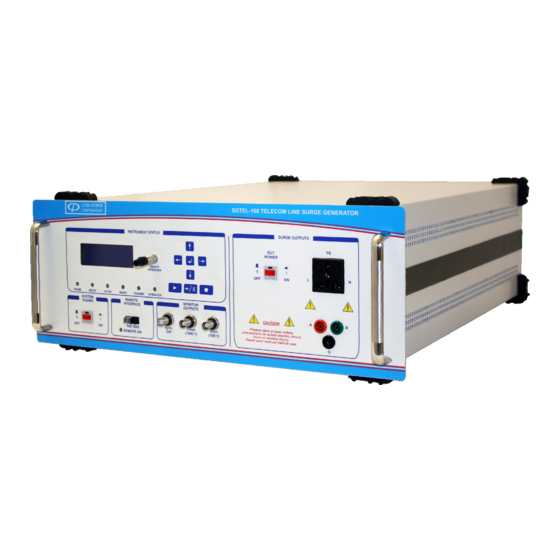
Page 10: Product Connections/Controls
This is the EUT port of the internal coupling/decoupling network (CDN). Power line surges, as well as EUT input power is provided through this port. Instrument Status LED Indicators These six LED indicators provide the present instrument status for the SGTEL-168. System Power Switch This switch toggles ON/OFF the SGTEL-168 surge generator. - Page 11 This port connects to the power source for the generator. See section 3.6 for input power specifications. SGTEL-168 System Power Switch This switch toggles on/off the SGTEL-168 system input power. When this switch is in the ‘ON’ position, the system may be turned on/off using the System Power Switch, located on the front panel 1 9 1 2 1 E l T o r o R d ●...
-
Page 12: Product Specifications
Page 12 of 54 INSTRUCTION MANUAL SGTEL-168 TELECOM LINE SURGE GENERATOR Product Specifications Output Waveform Parameters Open Circuit Rise Decay Short Circuit Rise Decay Voltage - Time - Time - Current - Surge Type Time - Tr Time (Volts) (μs) - Page 13 Page 13 of 54 INSTRUCTION MANUAL SGTEL-168 TELECOM LINE SURGE GENERATOR FIGURE 3 - Product Dimensions 1 9 1 2 1 E l T o r o R d ● S i l v e r a d o , C a l i f o r n i a 9 2 6 7 6 ● ( 9 4 9 ) 4 5 9 - 9 6 0 0 ● c o m - p o w e r . c o m...
-
Page 14: Setting Up The Sgtel-168
4.0 Setting up the SGTEL-168 In the following sections, guidance is provided pertaining to the external electrical connections/interconnections of the SGTEL-168 System and accessories. The guidance is given on a port-by-port basis. Input Power Line Ports WARNING - DO NOT EXCEED THE RELEVANT INPUT POWER SPECIFICATIONS DETAILED IN SECTION 3.5 AND ON THE REAR PANEL OF THE GENERATOR ITSELF. -
Page 15: Equipment Under Test (Eut) Power Input Port
4.1.2 Equipment Under Test (EUT) Power Input Port ONLY AFTER the SGTEL-168 is turned on, the power source which will power the Equipment Under Test (EUT) is to be connected to this input port through the provided, blue-colored AC power connector (wiring not included). -
Page 16: Turning On/Off Eut Power - Local Control
CDN output terminals. If the EUT power is not enabled on the SGTEL-168 front panel, the following message will be displayed: E U T... -
Page 17: Turning On/Off Eut Power - Remote Control
CDN output terminals. If the EUT power is not enabled on the SGTEL-168 front panel, the following message will be displayed: If the SGTEL-168 uses an power frequency phase detection circuit to determine whether AC power is present at the EUT power port. -
Page 18: Input/Output Ports
2 and 3 of the supplied, spare 7mm push-pull connector as shown in Figure 6. Remove the interlock key from the SGTEL-168 interlock port, and plug in the switch assembly, and the generator will now be enabled/disabled with the opening/closing of the switch contacts. -
Page 19: Fiber Optic Port
Setting up the Remote Interface As shown in Figure 7, connect the supplied fiber optic cable into the fiber optic port on the front of the SGTEL-168. Connect the opposite end of the fiber optic cable into the powered OTA-232 Optical Transreceiver Adapter. Finally, connect the OTA-232 Adapter to a computer with the Com-Power TransWare™... -
Page 20: Monitor Ports
Page 20 of 54 INSTRUCTION MANUAL SGTEL-168 TELECOM LINE SURGE GENERATOR Monitor Ports The monitor ports provide a convenient method for verification various surge waveform parameters, and triggering of oscilloscope measurements. 4.3.1 Sync Output Port (Sync. O/P) The SYNC OUTPUT port is provided as an alternative method of triggering the oscilloscope measurement. -
Page 21: Surge Generator Output Ports
Due to the presence of DANGEROUS VOLTAGES, the user should avoid all contact with these output port, as well as any cabling which connects to these ports while the SGTEL-168 is in operation. All connections should be made before applying power to the generator. -
Page 22: A/B/G) Surge Output Ports
Ideally, EUT lines under test should be fitted with 4mm safety socket connectors, and connected directly to the appropriate SGTEL-168 (A/B/G) output terminals as illustrated for each respective surge waveform in Figures 8, 9, 10, 11 and 12. -
Page 23: Type A - 800V Surge (Metallic) Terminal Connections
4-wire connection that uses simplex signaling, tip to ring-1 and ring to tip-1. The SGTEL-168 applies this surge between Terminals (A) and (B). Therefore, the EUT lines to be tested should be connected to these terminals for this surge, as shown in Figure 8. -
Page 24: Type A - 1500V Surge (Longitudinal) Terminal Connections
The SGTEL-168 applies this surge between Terminal (A) and the Ground Terminal (G). Therefore, the EUT lines to be tested should be connected to these terminals for this surge, as shown in Figure 9. -
Page 25: Type B - 1000V Surge (Metallic) Terminal Connections
4-wire connection that uses simplex signaling, tip to ring-1 and ring to tip-1. The SGTEL-168 applies this surge between Terminals (A) and (B). Therefore, the EUT lines to be tested should be connected to these terminals for this surge, as shown in Figure 10. -
Page 26: Type B - 1500V Surge (Longitudinal) Terminal Connections
The SGTEL-168 applies this surge from Terminals (A) and (B) to the Ground Terminal (G). Therefore, the EUT lines to be tested should be connected to these terminals for this surge, as shown in Figure 11. -
Page 27: Internal Powerline Cdn Surge Output Port
Page 27 of 54 INSTRUCTION MANUAL SGTEL-168 TELECOM LINE SURGE GENERATOR 4.4.2 Internal Powerline CDN Surge Output Port Powerline surges will always be applied through a coupling/decoupling network (CDN). The SGTEL-168 surge generator includes an internal CDN for DC or single-phase AC powered devices up to 16 amps. -
Page 28: Calibration Of Surge Output Waveforms
5.0 Calibration of Surge Output Waveforms This section provides guidance on the measurement (and associated calculations) of the SGTEL-168 Surge Generator output waveforms at the (A/B/G) output terminals and at the EUT power output port terminals. Recommended Test Equipment Listed below are the three key components recommended for surge waveform measurements. -
Page 29: Measurement Connections
Measurement Connections Examples of typical measurement connection arrangements at the surge output ports of the SGTEL-168 for both open circuit voltage (left) and short circuit current (right) are shown below in Figures 13, 14 and 15. FIGURE 13 -... -
Page 30: Surge Waveform Requirements
Page 30 of 54 INSTRUCTION MANUAL SGTEL-168 TELECOM LINE SURGE GENERATOR Surge Waveform Requirements The surge waveform requirements are defined in terms of both open circuit voltage and short circuit current waveform requirements. For both voltage and current waveforms, the following parameters are defined:... -
Page 31: Open Circuit Voltage Waveform Requirements
Page 31 of 54 INSTRUCTION MANUAL SGTEL-168 TELECOM LINE SURGE GENERATOR 5.4.1 Open Circuit Voltage Waveform Requirements The waveform in Figure 16 defines the open circuit voltage wave shape. FIGURE 16 - Open Circuit Voltage Wave Shape TABLE II –... -
Page 32: Measurement Of Voltage Waveform Parameters
Page 32 of 54 INSTRUCTION MANUAL SGTEL-168 TELECOM LINE SURGE GENERATOR 5.4.1.1 Measurement of Voltage Waveform Parameters This section discusses measurement process calculations proper determination individual waveform parameter values. PEAK VOLTAGE (V For positive surges, the Peak Voltage (V... -
Page 33: Example Calculations For Voltage Waveform Parameters
Page 33 of 54 INSTRUCTION MANUAL SGTEL-168 TELECOM LINE SURGE GENERATOR 5.4.1.2 Example calculations for Voltage Waveform Parameters Considered in the following example calculations is a typical Type A, Longitudinal, 1500V surge waveform. NOTE: The final values determined for each waveform parameter are shown in blue... -
Page 34: Short Circuit Current Waveform Parameters
Page 34 of 54 INSTRUCTION MANUAL SGTEL-168 TELECOM LINE SURGE GENERATOR 5.4.2 Short Circuit Current Waveform Parameters The waveform in Figure 17 defines the short circuit current wave shape. FIGURE 17 - Short Circuit Current Wave Shape TABLE III –... -
Page 35: Measurement Of Current Waveform Parameters
Page 35 of 54 INSTRUCTION MANUAL SGTEL-168 TELECOM LINE SURGE GENERATOR 5.4.2.1 Measurement of Current Waveform Parameters This section discusses the measurement process and calculation process for proper determination of the individual waveform parameter values. PEAK CURRENT The Peak Current (I ) is the highest measured current value within the envelope of the surge waveform. -
Page 36: Example Calculations For Current Waveform Parameters
Page 36 of 54 INSTRUCTION MANUAL SGTEL-168 TELECOM LINE SURGE GENERATOR 5.4.2.2 Example calculations for Current Waveform Parameters Considered in the following example calculations is a typical Type A, Longitudinal, 1500V surge waveform. NOTE: The final values determined for each waveform parameter are shown in blue... -
Page 37: Controlling The Sgtel-168 Via Its Front Panel
6.0 Controlling the SGTEL-168 via its Front Panel The SGTEL-168 Surge Generator is able to perform all of its individual functions from the front panel interface, as described in the following sections. For any given surge type, the user can define the coupling mode, number of surges and delay time between surges, and perform the tests. -
Page 38: Surge Menu
Page 38 of 54 INSTRUCTION MANUAL SGTEL-168 TELECOM LINE SURGE GENERATOR Surge Menu ► ■ From this single-page Surge Menu Screen, you are able to: a) define the SURGE type, b) define the coupling mode (terminals ON which the surge is coupled),... -
Page 39: Number Of Surges
Page 39 of 54 INSTRUCTION MANUAL SGTEL-168 TELECOM LINE SURGE GENERATOR 6.2.1.3 Number of Surges On the left side of the third line, ‘TESTS:’ defines the number of times that the selected surge will be repeated. This can be any number between ‘001’... -
Page 40: Run Test
Page 40 of 54 INSTRUCTION MANUAL SGTEL-168 TELECOM LINE SURGE GENERATOR 6.2.1.5 Run Test ► ■ Pressing at any time on this menu screen will start the test with the presently defined parameters. Refer to section 6.3 for details on the surge process. -
Page 41: Surging Process
Page 41 of 54 INSTRUCTION MANUAL SGTEL-168 TELECOM LINE SURGE GENERATOR Surging Process As discussed in section 6.2.1.5, the test is started by pressing the key. When the test begins, the bottom two lines of the display will change to show the current status of the test and current status of the generator. -
Page 42: Pausing The Test
Page 42 of 54 INSTRUCTION MANUAL SGTEL-168 TELECOM LINE SURGE GENERATOR 6.3.1 Pausing the Test At any point during the test, pressing the key will pause the current process and will show ‘PAUSED’ on the status line: To resume the test, press the key. -
Page 43: Transware™ Software
Page 43 of 54 INSTRUCTION MANUAL SGTEL-168 TELECOM LINE SURGE GENERATOR 7.0 TransWare™ Software Main Screen The layout of the main screen is as shown in Figure 18. FIGURE 18 - Main Screen - TransWare™ Software 1 9 1 2 1 E l T o r o R d ● S i l v e r a d o , C a l i f o r n i a 9 2 6 7 6 ● ( 9 4 9 ) 4 5 9 - 9 6 0 0 ● c o m - p o w e r . c o m... -
Page 44: Menu Bar
Page 44 of 54 INSTRUCTION MANUAL SGTEL-168 TELECOM LINE SURGE GENERATOR 7.1.1 Menu Bar The menu bar has three pull-down menus; File, Connect Device and Help. 7.1.1.1 File Menu The File pull-down menu functions in same manner as most windows- based software. -
Page 45: Connect Device Menu
Page 45 of 54 INSTRUCTION MANUAL SGTEL-168 TELECOM LINE SURGE GENERATOR 7.1.1.2 Connect Device Menu The Connect Device option is the only option for this menu. MENU ITEM DESCRIPTION Connect Device Initiates connection process between computer SGTEL-168 Surge Generator. -
Page 46: Tool Bar
Page 46 of 54 INSTRUCTION MANUAL SGTEL-168 TELECOM LINE SURGE GENERATOR 7.1.2 Tool Bar The tool bar provides easy-access shortcuts to several commands from the menu bar. 7.1.3 Sequencing Panel The sequencing panel contains all of the individual surge events in the test sequence. -
Page 47: User-Defined Surge Test Parameters
The user-defined test parameters are defined below: TEST PARAMETER DESCRIPTION Pause A check in this check box instructs the SGTEL-168 to pause the test prior to that surge event and display a message box with pre-defined message user. Upon... -
Page 48: Task Options Panel
Page 48 of 54 INSTRUCTION MANUAL SGTEL-168 TELECOM LINE SURGE GENERATOR 7.1.4 Task Options Panel The functions available on the TASK OPTIONS panel change depending on which of the two main functions is selected. Shown to the right is the TASK OPTIONS menu. When... -
Page 49: Sequence Editing Functions
Page 49 of 54 INSTRUCTION MANUAL SGTEL-168 TELECOM LINE SURGE GENERATOR 7.1.4.1 Sequence Editing Functions sequence editing functions are displayed on the TASK OPTIONS panel after selecting EDIT SEQUENCE on the TASK OPTIONS menu. Using these functions, the user can create and edit test sequences. -
Page 50: Logging Options
Page 50 of 54 INSTRUCTION MANUAL SGTEL-168 TELECOM LINE SURGE GENERATOR 7.1.4.2 Logging Options The IN-TEST OBSERVATION LOGGING functions are displayed task options panel after selecting LOGGING OPTIONS TASK OPTIONS menu. Here, the user can create a test log; after which he/she can edit, view, and enter comments into, the test log. - Page 51 Page 51 of 54 INSTRUCTION MANUAL SGTEL-168 TELECOM LINE SURGE GENERATOR After creating the test log, the IN-TEST OBSERVATION LOGGING functions are as shown to the left and described below. FUNCTION BUTTON DESCRIPTION Edit Test Log Allows the user to modify the information...
-
Page 52: Control Panel
The EUT power button enables/disables the EUT power output on the internal CDN. The EUT power switches on the rear and front panels of the SGTEL-168 must also be in the ‘ON’ position in order to enable EUT power. Refer to section 4.1.2 for more information. - Page 53 Page 53 of 54 INSTRUCTION MANUAL SGTEL-168 TELECOM LINE SURGE GENERATOR While test running, CONTROLS functions available are as shown to the right and described below. MENU ITEM DESCRIPTION The PAUSE button pauses the active test. To resume the test from the point at which the test was paused, press the button again.
-
Page 54: Warranty
SGTEL-168 TELECOM LINE SURGE GENERATOR 7.0 Warranty Com-Power warrants to its Customers that the products it manufactures will be free from defects in materials and workmanship for a period of three (3) years. This warranty shall not apply to: •...
Need help?
Do you have a question about the SGTEL-168 and is the answer not in the manual?
Questions and answers