Table of Contents
Advertisement
Quick Links
Advertisement
Table of Contents

Summary of Contents for RH CGS-240
- Page 1 CGS-240 Manual RH Systems, LLC 1225 W Houston Ave., Gilbert AZ, 85233...
-
Page 2: Table Of Contents
Change Units ..............................31 Connection of Other Instruments ........................ 31 Data Logging ..............................32 System Settings ............................33 4.10 Chamber ..............................34 4.11 Door ................................35 Calibration ..........................36 Pressure Calibration ............................. 36 CGS-240 Manual 6/15/2021 Page 2 of 148... - Page 3 10.4 Evaluating for Plateaus ..........................141 10.5 Selecting a Manual Reference ........................143 10.6 Calculating Calibration Coefficients ......................144 10.7 Plotting Residuals ............................146 10.8 Export Data ..............................147 Document History ......................148 CGS-240 Manual 6/15/2021 Page 3 of 148...
-
Page 4: Introduction
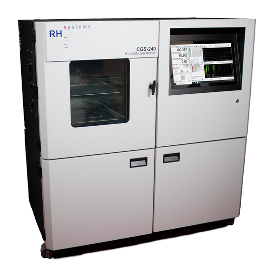
The RH Systems CGS-240 Humidity Generator is a system capable of continuous, high-accuracy humidity generation over a wide range of humidity, temperature, and flow rates. The CGS-240 design is an RHS hybrid two- pressure two-temperature system based on the fundamental two-pressure principle originally developed by NIST. -
Page 5: Theory Of Operation
Please note that the above expression ignores the use of enhancement factors which account for non-ideal properties of the air / water-vapor mixture, and is therefore only an approximation. More exacting equations which include enhancement factors are used internally within the system. CGS-240 Manual 6/15/2021 Page 5 of 148... -
Page 6: Combined Two-Pressure And Two-Temperature Principle
Saturation vapor pressure over water at a given ITS-90 temperature in the range –100 °C to +100 °C is defined by the formula − CGS-240 Manual 6/15/2021 Page 6 of 148... - Page 7 Equations 1 and 2. The effective saturation vapor pressure is related to the ideal by é = e·ƒ where é is the “effective” saturation vapor pressure e is the ideal saturation vapor pressure (as given in Equation 1 or 2) ƒ is the enhancement factor CGS-240 Manual 6/15/2021 Page 7 of 148...
- Page 8 –6 –7 1.6725084·10 6.3405286·10 for ice: 173.15 to 223.15 K (–100 °C to –50 °C) 223.15 to 273.15 K (–50 °C to 0°C) –2 –2 = –7.4712663·10 = –7.1044201·10 –4 –4 9.5972907·10 8.6786223·10 CGS-240 Manual 6/15/2021 Page 8 of 148...
- Page 9 2.0798233·10 2.1257969·10 –2.0156028·10 –1.0264612·10 –1 –1 4.6778925·10 1.4354796·10 –6 –9.2288067·10 –1 –2 = –1.3319669·10 = –8.2871619·10 –3 –3 5.6577518·10 2.3540411·10 –5 –5 = –7.5172865·10 = –2.4363951·10 CGS-240 Manual 6/15/2021 Page 9 of 148...
-
Page 10: Humidity Equations
Theory of operation HUMIDITY EQUATIONS The following equations are used in the CGS-240 to calculate various humidity parameters. These equations are not approximations, but rather account for the temperature differences between the saturator and chamber, and the non-ideal behavior of water vapor when admixed with air or other gases. - Page 11 Humidity ratio may also be computed and expressed in grams per kilogram and micrograms per gram. When expressed in micrograms per gram, humidity ratio is traditionally referred to in parts per million by weight (ppm CGS-240 Manual 6/15/2021 Page 11 of 148...
- Page 12 Specific humidity q is defined as the mass of the water vapor to the total mass of the gas mixture and is computed with the formula M f e (14) − M f e CGS-240 Manual 6/15/2021 Page 12 of 148...
-
Page 13: Installation
Plan on typical usage of about 1 gallon (4 liters) of distilled water per week. CGS-240 Manual 6/15/2021 Page 13 of 148... -
Page 14: Utility Connections
This connection is via the short blue tube located between the rear panel power switches. CGS-240 Manual 6/15/2021 Page 14 of 148... - Page 15 Figure 3.5 "CLOSED" Figure 3.6 "OPEN" Figure 3.4 Adjust the pressure regulator at the back of the unit to approximately 50-55 psi, see section 7.1.5.3. CGS-240 Manual 6/15/2021 Page 15 of 148...
- Page 16 Figure 3.7 Pressurized Air Connection PUR). Press the tube fully into the fitting to lock it into place. Turn on your external air source and power up the CGS-240 on the front panel below the monitor (the back panel power switch of the upper cabinet must also be on).
-
Page 17: Initial Preparation
The switch should illuminate, the monitor should activate, and the operating system (Windows 10) should boot. Follow section 4.1 through 4.2.1 to launch the RHS Control program and connect to the CGS-240 Humidity Generator. Interaction with the system is via touch screen or physical mouse/keyboard. To utilize the physical mouse/keyboard, plug them into the USB connectors located at the upper right rear of the system. - Page 18 Using the supplied funnel, slowly pour in 1 gallon of water (do not overflow the fill port). • Slowly add in 1.5 gallons of PG (do not overflow the fill port). Figure 3.12 Fluid Fill Port CGS-240 Manual 6/15/2021 Page 18 of 148...
- Page 19 The pumps take about a minute or so to ramp up to full speed each time they are restarted. Therefore, allow the pumps to run at least a minute between each Stop/Start sequence. CGS-240 Manual 6/15/2021...
- Page 20 • Ensure the Distilled Water Reservoir is at least half full. • Fill the supplied syringe by drawing distilled water into it. Figure 3.14 Filling the syringe CGS-240 Manual 6/15/2021 Page 20 of 148...
- Page 21 Simply run the generator again. It may take a few attempts to completely fill the pre-saturator the first time. Following this initial fill, the pre-saturator should automatically maintain its proper distilled water level, drawing from the reservoir as needed. CGS-240 Manual 6/15/2021 Page 21 of 148...
-
Page 22: Operation
These instrument specific files may be created and/or modified by end users, or they may be obtained from RH Systems for particular instruments. While these descriptor files are available for RH Systems brand products, they can also be created for a wide variety of instruments and are not limited by brand and model. -
Page 23: Introduction To Software
The splash screen indicates the software version number. Connection Window Log Interval Log On/Off Toggle Settings Figure 4.1 Select Units Expand Graphs to Start Close RHS Control Open the Open the fill window New Graph Connection window Profile window CGS-240 Manual 6/15/2021 Page 23 of 148... -
Page 24: Connection Window
Figure 4.2 4.2.1 CONNECT THE CGS-240 When the Connection window opens, it initiates an automatic search for attached instruments. To connect: 1. If the instrument you want to connect with is not listed, ensure it is plugged into a USB port (via a USB/232 converter as needed), then press the Search button. -
Page 25: Enter Set Point
Operation ENTER SET POINT A unique window appears within the main screen for each connected instrument. The following window is typical of a CGS-240. Undock this Open Secondary data / Minimize Open window away from coefficients menu window Mini Terminal... -
Page 26: Selecting Control Mode And Initiating Generate
4.4.1 HUMIDITY CONTROL MODE While in a valid humidity control mode (RH, FP, DP), the CGS-240 automatically determines suitable target values for saturation temperature and saturation pressure. 1. Click the drop-down menu to reveal the various control mode options. - Page 27 Figure 4.8 5. Once the setpoint is sent to the generator and accepted, the highlight disappears. A new value is then read from the CGS-240 and will be displayed. Saturation Temperature and Saturation Pressure setpoints will be automatically recomputed if needed.
- Page 28 Operation The CGS-240 automatically determines a suitable saturation temperature setpoint when entering a new humidity setpoint. The saturation temperature it determines depends on the available system pressure. If the system is unable to reach the desired humidity setpoint using pressure alone, it will automatically adjust saturation temperature as needed to generate the desired humidity value.
-
Page 29: Viewing Data Numerically And Graphically
Change Graph Color Enable/Disable current data plot Figure 4.15 Start a new Click to Add Plot Note, X-Axis manual Minimize Close graph then click within plot to entry scale Graph Graph insert note. CGS-240 Manual 6/15/2021 Page 29 of 148... - Page 30 • Open profile • Save profile • Start profile • Pause profile Control pull-down • Stop profile Set point entry Profile Total Time Move set-point up/down Timer and set-point controls for run time CGS-240 Manual 6/15/2021 Page 30 of 148...
-
Page 31: Change Units
A variety of other instrument may also be connected to RHS Control. If the instrument has a serial port, connected via one of the four serial ports (left on CGS-240) or via a USB/232 converter connected to one of the USB ports (right side of the CGS-240), and a properly written description file (.json file), the Connection window should be... -
Page 32: Data Logging
Operation Four Serial Port Panel CGS-240 (optional on CGS-240) These ports mimic the operation and pinout of standard PC serial ports and can independently operate at a variety of baud rates and communication protocols. Generally, instrument connections are made using an RS-232 Extension... -
Page 33: System Settings
Log Configuration allows for changes to the log file data formatting options. It also allows setting the maximum log file size. Once the size is reached, the file will close and a new log file will automatically be generated. Figure 4.24 CGS-240 Manual 6/15/2021 Page 33 of 148... -
Page 34: Chamber
Figure 4.25 Temperature Cable Chamber Temperature Probe Chamber Fan Chamber Humidity Inlet Tube Chamber Pressure Shelving System Multiple Shelving Locations Heat Dispersion Plate (optional) Air Flow Vents Figure 4.26 CGS-240 Manual 6/15/2021 Page 34 of 148... -
Page 35: Door
The liquid jacketed chamber door uses heavy duty hinges, a recessed latching mechanism, a built-in light, and built-in heaters for the door frame and window. The liquid jacketing of the door and window aid significantly in the chamber stabilization and temperature uniformity. Figure 4.28 Figure 4.27 CGS-240 Manual 6/15/2021 Page 35 of 148... -
Page 36: Calibration
Stable pressure source, pressure range capable of: Ambient to 25 psia for low range transducer Ambient to 150 psia for high range transducer • Pressure controller and/or standard, detailed in section 5. • 9/16” open end wrench. CGS-240 Manual 6/15/2021 Page 36 of 148... - Page 37 + a2٠(P + a3٠(P actual sensor sensor sensor To alter that calibration using the CGS-240 in-system calibration method, those coefficients will be adjusted to bring the out-of-tolerance P readings to in-tolerance P readings. Expected sensor actual coefficient ranges following in-system calibration adjustment are:...
- Page 38 5.1.2 CALIBRATION OF PRESSURE TRANSDUCERS Bring the CGS-240 to a pressure source with a pressure controller and/or standard, or the pressure controller and/or standard may be brought to the CGS-240 if a suitable pressure source is available at location. 1) Following the operator’s manual for the pressure controller/standard (or internal procedures), connect the pressure standard to the pressure sensor.
- Page 39 Calibration 5) Open Cal Mode by selecting Utilities from the drop-down menu. 6) Click the Calibration button. By default, the Cal Mode window opens with the Temperature sensors (Ts and Tc) selected. CGS-240 Manual 6/15/2021 Page 39 of 148...
- Page 40 For the [PH] High Pressure Sensor, the Calibration range is ambient to 150 psia. Calibrate this sensor with approximate pressures of ambient, 25, 50, 75, 100, 125, and psia. 9) Monitor the PL or PH sensor value by selecting Measurements from the drop-down menu. CGS-240 Manual 6/15/2021 Page 40 of 148...
- Page 41 The Calculate button remains disabled until the minimum number of values are entered. • 3 order polynomial – minimum of 5 points • 2 order polynomial – minimum of 4 points • Linear – minimum of 3 points CGS-240 Manual 6/15/2021 Page 41 of 148...
- Page 42 Calculate icon will be disabled. As shown in the example below, changing from the 2 order to 3 order polynomial will disable the Calculate icon if the minimum number of values have not yet been entered. CGS-240 Manual 6/15/2021 Page 42 of 148...
- Page 43 5.1.3, Pressure Sensor Reinstallation. Otherwise, continue with Step 13 to save the new coefficients. 13) When you are ready to save the new coefficients to the CGS-240, click the Save icon. A pop-up message confirms completion of the save. CGS-240 Manual...
- Page 44 5.1.4 ALTERNATIVE PRESSURE CALIBRATION PROCEDURE: INDEPENDENT SENSOR CALIBRATION This procedure assumes the sensors are calibrated independently of the CGS-240 Refer to section 5.1.1 for instructions on pressure sensor removal. CGS-240 Manual 6/15/2021...
- Page 45 Coefficient Default 3) Upon return of the fully calibrated sensors, the CGS-240 must have Default Coefficients entered. The use of default coefficients ensures that the instrument will not perform any post-measurement corrections to the newly calibrate pressure sensor data.
-
Page 46: Temperature Calibration
[Ts] Saturator Temperature Probe The temperature probe calibrations should be performed as a system. The probes will be removed from the insertion points of the CGS-240 but will remain connected to the electrical system. Both probes can be run simultaneously. - Page 47 Calibration 5.2.1 TEMPERATURE PROBE REMOVAL 1) Power down the CGS-240: a. Press the front panel power button and wait for the unit to complete shutdown. b. Switch the main power Off. 2) Remove the back, top, and right-side panels. Tools are not required for the removal of any access panels.
- Page 48 CALIBRATION OF T AND T PROBES 1) Bring the CGS-240 to a location which has a suitable calibration bath and temperature standard, or the calibration bath and temperature standard may be brought to the CGS-240. 2) Power up the CGS-240: a.
- Page 49 Doing so could damage the probes. b. Set the bath temperature to a setpoint below 0 °C (-20 °C is recommended). Open Cal Mode by selecting Utilities from the drop- down menu. Click the Calibration button. CGS-240 Manual 6/15/2021 Page 49 of 148...
- Page 50 Otherwise, continue with steps 10 through 12 in order to calculate and save new coefficients. 12) After entering the minimum required number of readings, or more, click the Calculate icon. The new coefficients will appear on the bottom portion of the window. CGS-240 Manual 6/15/2021 Page 50 of 148...
- Page 51 TEMPERATURE PROBE REINSTALLATION 1) Clean any residue from the probes after removing them from the bath. 2) Place the chamber temperature probe in the chamber, coiling it around the cable holder, as needed. CGS-240 Manual 6/15/2021 Page 51 of 148...
- Page 52 However, an open vent valve causes the water tank to heat and cool with the chamber and saturator. The system operates more efficiently with a closed vent valve, which then provides some isolation of the tank from the chamber and saturator temperatures. CGS-240 Manual 6/15/2021 Page 52 of 148...
-
Page 53: Subsystems
When the main power switch is on, the 5V DC is also supplied through a diode, D2, to the solid-state relay, SSR6, which energizes the 12V and 24V power supplies. Figure 6.1 CGS-240 Manual 6/15/2021 Page 53 of 148... - Page 54 ECB software consists of RHS custom developed code, coupled with a high-speed multi-tasking real-time operating system. Via this multi-tasking embedded software, Figure 6.3 the ECB orchestrates the second-to-second operation of the humidity generator based CGS-240 Manual 6/15/2021 Page 54 of 148...
- Page 55 Subsystems on command input from any of the RS-232 ports. Supervisory operation such as set points (RH, dew point, flowrate, etc.) are transmitted to the controller board via the touch monitor and PC. The job of the ECB is to accept these set points, continuously measure the various analog and digital sensors, and control the various electro- mechanical actuators in order to bring about and maintain the desired set point conditions.
- Page 56 Output A4 of the ECB main controller board activates SSR5. When activated, AC power is applied through SSR5 and circuit breaker, CB6, to the chamber fan activating the fan. The fan is generally on or off and is not speed controlled. CGS-240 Manual 6/15/2021 Page 56 of 148...
- Page 57 ECB RLY 14. When the light is turned on, the ECB RLY 14 sources 24VDC to active the light. An LED at RLY 14 also indicates the relay status. When the LED is on, the chamber light is on. CGS-240 Manual 6/15/2021...
-
Page 58: Pneumatic System
Gas exhausts to the room. A normally open solenoid valve, SOL 2, is used to depressurize the saturator during shutdown and whenever the humidity generator is powered off. CGS-240 Manual 6/15/2021 Page 58 of 148... - Page 59 The stepper motor is positioned by a stepper controller, SD1. The ECB communicates with the stepper controller via UART2 configured for 2-wire RS-245 communication. Commands are sent to and received from the stepper controller via UART2_ D+ and D-. CGS-240 Manual 6/15/2021 Page 59 of 148...
- Page 60 Based on positioning commands from the ECB, the stepper controller actuates the stepper motor. A single, optical limit switch, SW2, connects to the stepper controller’s X3 digital input and identifies Figure 6.12 the valves fully closed (home) position. CGS-240 Manual 6/15/2021 Page 60 of 148...
- Page 61 When sat pressure is higher than 25 psia, SOL 5 activates to ensure the low range sensor measures only the chamber pressure during that time. CGS-240 Manual 6/15/2021 Page 61 of 148...
-
Page 62: Fluid System
This tank is connected via a suction tube to the presaturator via the preset fill pump. The operator is responsible for maintaining distilled water in this tank, filling it when required. CGS-240 Manual 6/15/2021 Page 62 of 148... - Page 63 DC CONTROL - RLY 4. The square wave sequentially activates/deactivates the solenoid of P2 causing it to pump water into the presaturator. When water is detected at the preset liquid level sensor, the LED turns off. Figure 6.18 CGS-240 Manual 6/15/2021 Page 63 of 148...
- Page 64 Both the saturator fluid circulation system and chamber fluid circulation system share a common expansion tank. The tank is located at the upper left-hand corner of the system, behind the chamber. CGS-240 Manual 6/15/2021 Page 64 of 148...
-
Page 65: Refrigeration System
The high-pressure liquid accumulates in the receiver. Liquid from the receiver passes through the filter/drier and the site glass. This high-pressure liquid is Figure 6.23 CGS-240 Manual 6/15/2021 Page 65 of 148... - Page 66 Cooling is accomplished by refrigerant injection through the sat cool solenoid valve, SOL 7. This valve is actuated by a 24VDC pulse width Figure 6.24 modulated signal. When energized, the valve opens allowing refrigerant to be CGS-240 Manual 6/15/2021 Page 66 of 148...
- Page 67 The pulse width of the valve directly controls the amount of refrigerant injected, thereby affecting the temperature of the fluid. The valve is generally pulsed at a fixed interval with varying pulse width. When the system Figure 6.26 CGS-240 Manual 6/15/2021 Page 67 of 148...
-
Page 68: Heaters
A2’s digital output is visually indicated with an adjacent LED. The heater ON status is also indicated with an LED on the SSR3. AC power to the heater is also protected by a thermal cutout switch, TH2, which removes AC power in the event of over temperature. CGS-240 Manual 6/15/2021 Page 68 of 148... - Page 69 The expansion valve is heated and maintained at temperature through pulse width modulation of RLY 12 using feedback from the expansion valve temperature sensor, T . The valve is normally wrapped in a custom molded thermal insulator (not shown in Figure 6.32). CGS-240 Manual 6/15/2021 Page 69 of 148...
- Page 70 ECB’s DC CONTROL – RLY 19 to source 24 VDC to the heaters. Figure 6.33 RLY 19’s output is visually indicated with an adjacent LED. When the LED is ON, the heater is active. CGS-240 Manual 6/15/2021 Page 70 of 148...
-
Page 71: Connections To The Ecb
ECB and reference the specific sections of this manual where each input or output is discussed. RLY1 – RLY12 AD0 – AD7 A0 – A7 B0 – B3 LVL1 – LVL4 Figure 6.34 CGS-240 Manual 6/15/2021 Page 71 of 148... - Page 72 RLY 15 SOL 10, Dryer RLY 16 H7, Upper Access Section 6.5.5 Enable/Disable Port Heater (Optional) RLY 17 H8, Middle Access Section 6.5.5 RLY 18 H9, Lower Access Section 6.5.5 Port Heater Port Heater CGS-240 Manual 6/15/2021 Page 72 of 148...
- Page 73 12 VDC power available to directly power the connected devices or sensors. Analog Input Description Reference Refrigeration High-side Pressure Sensor Section 6.4.6 , Refrigeration Low-side Pressure Sensor Section 6.4.6 , Tube Liquid Presence Section 6.3.3 Temp Board power Section 6.1.3 AD4-AD7 6.6.4 LEVEL INPUTS CGS-240 Manual 6/15/2021 Page 73 of 148...
- Page 74 RS-232, 9600, 8, 1, N Section 3.3.1 UART5 Internal PC RS-232, 9600, 8, 1, N Section 3.3.1 UART6 RS-232, 9600, 8, 1, N UART7 Temperature Board RS-232, 9600, 8, 1, N Section 6.1.3 CGS-240 Manual 6/15/2021 Page 74 of 148...
-
Page 75: Temperature Measurements
13-16. The system requires a minimum of 2 reference resistors but can utilize up to 4 references resistors if present. The Precision Resistance Measurement board communicates via RS-232 to the ECB UART 7. Figure 6.35 CGS-240 Manual 6/15/2021 Page 75 of 148... -
Page 76: Troubleshoot/Maintenance
Remove the top and rear panels to check the fluid level of the tank. The level should be between the minimum and maximum marks indicated on the tank. CGS-240 Manual 6/15/2021 Page 76 of 148... - Page 77 To perform this test, set the generator for operation at 20 l/min and 25% RH at 25°C. Press the run button to ensure the generator is operating. Once the system is stabilized and it is flowing approximately 20 l/min, check the output of the PSI pressure indicator on the front panel, or the pressure gauge on the pressure regulator.
- Page 78 7) Tare the flow meter again as done in step 3. 8) Unlock the red button by rotating a quarter turn counterclockwise. The indicated pressure on the regulator gauge will slowly drop towards 0, this is normal. CGS-240 Manual 6/15/2021 Page 78 of 148...
- Page 79 1. Remove the three (3) m3x40mm and three (3) m4 x10mm screws from the valve being disassembled. Figure 7.1 Figure 7.2 2. Remove the valve from the Saturator box. Take note not to lose the wave spring around the Teflon seal (seen in figure 7.5). Figure 7.3 Figure 7.4 CGS-240 Manual 6/15/2021 Page 79 of 148...
- Page 80 6. Once separated (as seen in Figure 7.8) inspect the O-rings for damage. Replace as necessary. The plug O-rings are Viton -115. Grease lightly with a silicone-based O-ring lubricant. Tighten the set screws that secure the motor shaft to the plug. Figure 7.8 CGS-240 Manual 6/15/2021 Page 80 of 148...
- Page 81 Troubleshoot/Maintenance 7. The Teflon seal has a -016 Viton O-ring that should be checked and lightly greased upon reassembly. 8. Assembly is the reverse of disassembly. CGS-240 Manual 6/15/2021 Page 81 of 148...
-
Page 82: Troubleshooting
ESD will show red in RHS Control and shut the machine down. A warning will show up as yellow in RHS Control and will not influence the machine's running. If warning or errors persist after you’ve performed the resolution, perform full power cycle before contacting the Support team at RH Systems (support@rhs.com). EMERGENCY SHUTDOWN CODES... - Page 83 Check pre saturator temperature sensor (Ch1) connection or check temperature measurement board (see section 6.7 or 6.1.3). [Ts] Sat Temperature Out of Saturator temperature is out of Verify saturator Range operating range. temperature. Check saturator CGS-240 Manual 6/15/2021 Page 83 of 148...
- Page 84 Verify saturator pressure. Range operating range. Check supply pressure (see section 6.2.1). Check flow and expansion valves (see section 6.2.3 and 6.2.5) Check pressure sensor power and connection (see section 6.2.6 or 6.6.6). CGS-240 Manual 6/15/2021 Page 84 of 148...
- Page 85 6.2.6 or 6.6.6). Faulty Saturator/Chamber select solenoids (SOL4 & SOL5) (see section 6.2.7). [PL] Pressure Low Range Out Low range pressure sensor is out of Verify pressure. of Range operating range. Check pressure sensor CGS-240 Manual 6/15/2021 Page 85 of 148...
- Page 86 (see section 6.7 or 6.1.3). [Pai] Regulated Air-in Pressure Regulated air-in pressure is too high. Check that supply pressure high is below 175psi. Check pressure indication on dial gauge (see section CGS-240 Manual 6/15/2021 Page 86 of 148...
- Page 87 6.5.5 or 6.1.3). [Tp] Presat temperature low Pre saturator temperature is too low. Verify pre saturator temperature. Check pre saturator temperature sensor (Ch1) connection or check temperature measurement board (see section 6.7 or 6.1.3). CGS-240 Manual 6/15/2021 Page 87 of 148...
- Page 88 Check upper chamber access port temperature sensor (Ch10) connection or check temperature measurement board (see section 6.5.5 or 6.1.3). Check upper access port heater (see section 6.5.5). CGS-240 Manual 6/15/2021 Page 88 of 148...
- Page 89 Temperature is too low. Check lower chamber access port temperature sensor (Ch12) connection or check temperature measurement board (see section 6.5.5 or 6.1.3). Check upper access port heater (see section 6.5.5). CGS-240 Manual 6/15/2021 Page 89 of 148...
-
Page 90: Illustrated Parts Breakdown
DIN 912 - M4 x 8 generic Door Pass-Through 17.01/042.0 RH Systems Housing Pass-Through 17.01/042.1 RH Systems Housing Pass-Through - clip 17.01/042.2 RH Systems Door Pass-Through - clip 17.01/042.3 RH Systems Chamber seal 08.01K RH Systems CGS-240 Manual 6/15/2021 Page 90 of 148... - Page 91 Right housing cover 873.01/252.0 RH Systems Left housing cover 873.01/253.0 RH Systems Back housing cover 873.01/254.0 RH Systems Accessport cover plate 873.01/255.0 RH Systems Accessport 873.01/261.0 RH Systems Accessport plug 873.01/262.0 RH Systems CGS-240 Manual 6/15/2021 Page 91 of 148...
- Page 92 Door supply tube 12-10_3 RH Systems Drain tube 12-10_4 RH Systems Expansion vessel drain tube 12-10_5 RH Systems Insulation Kaiflex 9-10 Kaiflex 9-10 Kaimann GmbH Main Power Switch Push Button ULV4F2GSSG545 E-Switch ehg_2b_306_cym ehg_2b_306_cym Lemo CGS-240 Manual 6/15/2021 Page 92 of 148...
- Page 93 PFA Tubing, 1/4 in. OD x 0.047 in. Wall (Qty. in feet) TPFA1/4 Generic Diaphragm liquid pump 5002F 53001003 Gardner Denver 18-8 Stainless Steel Button Head Hex Drive Screw, 8-32 Thread Size, 1/2" Long BHCS8-32x1/2 Generic CGS-240 Manual 6/15/2021 Page 93 of 148...
- Page 94 18.5" Open Frame Multi Point Capacitive Touch M18568C-OF Mimo Monitors 1366x768 Display, Ext. Power Supply Incl. Monitor Bracket P-RH013775 RH Systems NEMA-17 Bipolar Stepper with 26.85:1 Gearbox 42STH38 Dongzheng Motor Button Head Hex Drive Screw, Passivated 18-8 BHCSM4x22 generic CGS-240 Manual 6/15/2021 Page 94 of 148...
- Page 95 DIN Rail Power Supplies 60W 12V 5A 180- 550Vin DIN WDR-60-12 Mean Well DIN Rail Power Supplies 10W 5V 2A MDR-10-5 Mean Well Ground modular terminal block - UT 6-PE 3044157 Phoenix Contact CGS-240 Manual 6/15/2021 Page 95 of 148...
- Page 96 Watlow Sat Heater, 1/4" 600W 2088-7818 Watlow Bath Heater, 3/8" 1500W 2087-0976 Watlow Water Separator AMG150C-N02BC Mist Separator AMH150C-N02C-T Membrane Air Dryer IDG5-N02 Spacer Y200-A Air Dryer Assembly Bracket AMG150C-N02BCBracket AirDryerMount P-RH013993 RHSystems CGS-240 Manual 6/15/2021 Page 96 of 148...
-
Page 97: Illustrations
Illustrated Parts Breakdown ILLUSTRATIONS Figure 8.1: CGS-240 CGS-240 Manual 6/15/2021 Page 97 of 148... - Page 98 Illustrated Parts Breakdown Figure 8.2 CGS-240 Manual 6/15/2021 Page 98 of 148...
- Page 99 Illustrated Parts Breakdown Figure 8.3 CGS-240 Manual 6/15/2021 Page 99 of 148...
- Page 100 Illustrated Parts Breakdown Figure 8.4 CGS-240 Manual 6/15/2021 Page 100 of 148...
- Page 101 Illustrated Parts Breakdown Figure 8.5 Figure 8.6 CGS-240 Manual 6/15/2021 Page 101 of 148...
- Page 102 Illustrated Parts Breakdown Figure 8.7 Figure 8.8 CGS-240 Manual 6/15/2021 Page 102 of 148...
- Page 103 Illustrated Parts Breakdown Figure 8.9 CGS-240 Manual 6/15/2021 Page 103 of 148...
- Page 104 Illustrated Parts Breakdown Figure 8.10 CGS-240 Manual 6/15/2021 Page 104 of 148...
- Page 105 Illustrated Parts Breakdown Figure 8.11 Figure 8.12 CGS-240 Manual 6/15/2021 Page 105 of 148...
- Page 106 Illustrated Parts Breakdown Figure 8.13 Figure 8.14 CGS-240 Manual 6/15/2021 Page 106 of 148...
- Page 107 Illustrated Parts Breakdown Figure 8.15 CGS-240 Manual 6/15/2021 Page 107 of 148...
- Page 108 Illustrated Parts Breakdown Figure 8.16 CGS-240 Manual 6/15/2021 Page 108 of 148...
- Page 109 Illustrated Parts Breakdown Figure 8.17 CGS-240 Manual 6/15/2021 Page 109 of 148...
- Page 110 Illustrated Parts Breakdown Figure 8.18 CGS-240 Manual 6/15/2021 Page 110 of 148...
- Page 111 Illustrated Parts Breakdown Figure 8.19 CGS-240 Manual 6/15/2021 Page 111 of 148...
- Page 112 Illustrated Parts Breakdown Figure 8.20 CGS-240 Manual 6/15/2021 Page 112 of 148...
- Page 113 Illustrated Parts Breakdown Figure 8.21 CGS-240 Manual 6/15/2021 Page 113 of 148...
- Page 114 Illustrated Parts Breakdown Figure 8.22 CGS-240 Manual 6/15/2021 Page 114 of 148...
- Page 115 Illustrated Parts Breakdown Figure 8.23 CGS-240 Manual 6/15/2021 Page 115 of 148...
- Page 116 Illustrated Parts Breakdown Figure 8.24 CGS-240 Manual 6/15/2021 Page 116 of 148...
- Page 117 Illustrated Parts Breakdown Figure 8.25 CGS-240 Manual 6/15/2021 Page 117 of 148...
- Page 118 Illustrated Parts Breakdown Figure 8.26 CGS-240 Manual 6/15/2021 Page 118 of 148...
-
Page 119: Drawings
Drawings DRAWINGS The legend is followed by drawings of the refrigeration system, pneumatic system, and fluid system. The electronic board drawings are included in this portion of the manual. CGS-240 Manual 6/15/2021 Page 119 of 148... - Page 120 Drawings CGS-240 Manual 6/15/2021 Page 120 of 148...
- Page 121 Drawings Figure 9.3 Refrigeration System CGS-240 Manual 6/15/2021 Page 121 of 148...
- Page 122 Drawings Figure 9.4 Pneumatic System CGS-240 Manual 6/15/2021 Page 122 of 148...
- Page 123 Drawings Figure 9.5 Fluid System CGS-240 Manual 6/15/2021 Page 123 of 148...
- Page 124 Drawings Figure 9.6 AC Distribution CGS-240 Manual 6/15/2021 Page 124 of 148...
- Page 125 Drawings Figure 9.7 AD0-3 & LVL4 CGS-240 Manual 6/15/2021 Page 125 of 148...
- Page 126 Drawings Figure 9.8 Power Distribution CGS-240 Manual 6/15/2021 Page 126 of 148...
- Page 127 Drawings Figure 9.9 RLY 1-14 CGS-240 Manual 6/15/2021 Page 127 of 148...
- Page 128 Drawings Figure 9.10 PT 12 Temp Board CGS-240 Manual 6/15/2021 Page 128 of 148...
- Page 129 Drawings Figure 9.11 UART 0-3 CGS-240 Manual 6/15/2021 Page 129 of 148...
- Page 130 Drawings Figure 9.12 Access to Presat Drain Fitting CGS-240 Manual 6/15/2021 Page 130 of 148...
- Page 131 Drawings Figure 9.13 Access to Sat Drain Fittings CGS-240 Manual 6/15/2021 Page 131 of 148...
- Page 132 Drawings Figure 9.14 Temperature Probes CGS-240 Manual 6/15/2021 Page 132 of 148...
- Page 133 Drawings Figure 9.15 Pressure Transducers & Manifold CGS-240 Manual 6/15/2021 Page 133 of 148...
-
Page 134: Rhs Plateau Software
RHS PLATEAU SOFTWARE The CGS-240 RHS Plateau software may be used to calibrate a device given a set of test data (Unit Under Test or UUT) and a set of reference data. It evaluates data, finding plateaus, it then evaluates the plateau for the most stable sections based on standard deviation. - Page 135 The second tab contains the above-mentioned data corrected by the coefficients calculated by selecting the Calculate button which will be explained further within ‘#5 Utility Settings’. The Plateau(s) windows are shown in Figure 5.9 and 5.10. Figure 5.9 Figure 5.10 CGS-240 Manual 6/15/2021 Page 135 of 148...
-
Page 136: Sequence Of Events
(in the File pull down menu) to confirm that your file delimiter and datetime formats are correct. As shown in Figure 5.11, to display File Settings settings, click on > Figure 5.11 CGS-240 Manual 6/15/2021 Page 136 of 148... - Page 137 Figure 5.14 shows the menu options for File DateTime Format, which specifies the format your date data is using in your data file. If <AUTO> is selected RHS Plateau will attempt all of the options. Figure 5.14 CGS-240 Manual 6/15/2021 Page 137 of 148...
- Page 138 If <AUTO> is selected RHS Plateau defaults to Year-Month- Day_Hour:Min:Sec. Figure 5.15 Once plotted, the X-Axis will be labeled with the chosen datetime stamp, example shown below in Figure 5.16. Figure 5.16 CGS-240 Manual 6/15/2021 Page 138 of 148...
-
Page 139: Data File Selection
This can be done as many times as there are data files, but RHS Plateau will not reload the same file. Additionally, if a file is changed you must reload the file into RHS Plateau. Figure 5.19 CGS-240 Manual 6/15/2021 Page 139 of 148... - Page 140 For temperature data, the reference will be in degrees (°C), but the UUT should be in ohms (Ω). For example, for a UUT of Sat Temperature, select “Sat Probe Resistance,” rather than “Sat Temp.” Figure 5.22 CGS-240 Manual 6/15/2021 Page 140 of 148...
-
Page 141: Evaluating For Plateaus
On the graph interface a number of colored boxes representing each of the plateaus will appear, as shown in Figure 5.25. To view these more closely it is possible to zoom in on the graph until only the plateau data is shown. CGS-240 Manual 6/15/2021... - Page 142 • An input box labeled Ref Mean which contains the mean value of the reference data set over the Figure 5.26 specified plateau indices. CGS-240 Manual 6/15/2021 Page 142 of 148...
-
Page 143: Selecting A Manual Reference
Where you would normally select a reference data set, instead of clicking the ‘Select as Reference’ button, select the ‘Use Manual Reference’ button. Then go through the normal steps up through the section ‘Evaluating for Plateaus’. Figure 5.28 CGS-240 Manual 6/15/2021 Page 143 of 148... -
Page 144: Calculating Calibration Coefficients
(1 + �� ∗ �� + �� ∗ �� Where �� is the thermometer resistance (in ohms) and �� is the thermometer temperature (in °C). • ITS-90 • Polynomial: User option of 1 , or 3 order polynomial CGS-240 Manual 6/15/2021 Page 144 of 148... - Page 145 A pop-up window opens (as shown in Figure 5.33). Enter a Serial Number and click OK. Figure 5.33 Once confirmed, a file browser opens (as shown in Figure 5.34). Choose an appropriate save location for the file. Figure 5.34 CGS-240 Manual 6/15/2021 Page 145 of 148...
-
Page 146: Plotting Residuals
A few moments after the ‘Plot Residuals’ button is clicked a number of changes will occur on RHS Plateau. A new plot will appear containing the UUT data with the coefficients applied, and the original reference data. Shown in Figure 5.37. Figure 5.37 CGS-240 Manual 6/15/2021 Page 146 of 148... -
Page 147: Export Data
This file contains both the calculated coefficients as well as the data that was used in those calculations. This file is a useful resource for auditing purposes where validation of plateau’s curve fit capability is desired. Figure 5.39 CGS-240 Manual 6/15/2021 Page 147 of 148... -
Page 148: Document History
12 Apr 2021 Expanded content in Calibration chapter, Erik Image Updates, Formatting Improvements 05 May 2021 Addition of Cal Mode to Calibration chapter, Erik Relocation of Plateau section, Formatting changes to Illustrated Parts section CGS-240 Manual 6/15/2021 Page 148 of 148...
Need help?
Do you have a question about the CGS-240 and is the answer not in the manual?
Questions and answers