Table of Contents
Advertisement
Available languages
Available languages
Quick Links
Version 1.0
Published January 2021
Copyright©2021 ASRock INC. All rights reserved.
Copyright Notice:
No part of this documentation may be reproduced, transcribed, transmitted, or
translated in any language, in any form or by any means, except duplication of
documentation by the purchaser for backup purpose, without written consent of
ASRock Inc.
Products and corporate names appearing in this documentation may or may not
be registered trademarks or copyrights of their respective companies, and are used
only for identification or explanation and to the owners' benefit, without intent to
infringe.
Disclaimer:
Specifications and information contained in this documentation are furnished for
informational use only and subject to change without notice, and should not be
constructed as a commitment by ASRock. ASRock assumes no responsibility for
any errors or omissions that may appear in this documentation.
With respect to the contents of this documentation, ASRock does not provide
warranty of any kind, either expressed or implied, including but not limited to
the implied warranties or conditions of merchantability or fitness for a particular
purpose.
In no event shall ASRock, its directors, officers, employees, or agents be liable for
any indirect, special, incidental, or consequential damages (including damages for
loss of profits, loss of business, loss of data, interruption of business and the like),
even if ASRock has been advised of the possibility of such damages arising from any
defect or error in the documentation or product.
This device complies with Part 15 of the FCC Rules. Operation is subject to the following
two conditions:
(1) this device may not cause harmful interference, and
(2) this device must accept any interference received, including interference that
may cause undesired operation.
CALIFORNIA, USA ONLY
The Lithium battery adopted on this motherboard contains Perchlorate, a toxic substance
controlled in Perchlorate Best Management Practices (BMP) regulations passed by the
California Legislature. When you discard the Lithium battery in California, USA, please
follow the related regulations in advance.
"Perchlorate Material-special handling may apply, see www.dtsc.ca.gov/hazardouswaste/
perchlorate"
ASRock Website: http://www.asrock.com
Advertisement
Chapters
Table of Contents

Related Manuals for ASROCK Z590 Extreme WiFi 6E


Summary of Contents for ASROCK Z590 Extreme WiFi 6E
- Page 1 (including damages for loss of profits, loss of business, loss of data, interruption of business and the like), even if ASRock has been advised of the possibility of such damages arising from any defect or error in the documentation or product.
- Page 2 If you require assistance please call ASRock Tel : +886-2-28965588 ext.123 (Standard International call charges apply) The terms HDMI®...
- Page 3 ES OF ANY KIND WHETHER UNDER THIS AGREEMENT OR OTHERWISE, EVEN IF INTEL HAS BEEN ADVISED OF THE POSSIBILITY OF SUCH DAMAGES. LICENSE TO USE COMMENTS AND SUGGESTIONS. This Agreement does NOT obligate Licensee to provide Intel with comments or suggestions regarding the Software. However, if Licensee provides Intel with comments or suggestions for the modification, correction, improvement or enhancement of (a) the Software or (b) Intel products or processes that work with the Software, Licensee grants to Intel a non-exclusive, worldwide,...
- Page 4 CE Warning This device complies with directive 2014/53/EU issued by the Commision of the European Community. This equipment complies with EU radiation exposure limits set forth for an uncontrolled environment. This equipment should be installed and operated with minimum distance 20cm between the radiator &...
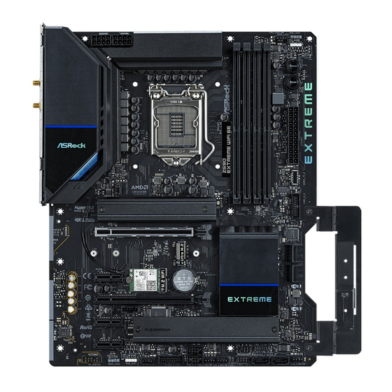
- Page 5 Z590 Extreme WiFi 6E Motherboard Layout CPU_FAN2/WP ADDR_LED2 ATX12V1 ATX12V2 RGB_LED2 Power Reset Top: USB 3.2 Gen2 T: USB31_TA_1 RJ-45 B: USB31_TC_1 (I219V) Top: 2.5G USB31_TC_2 CHA_FAN1/WP CPU_FAN1 PCIE1 Intel Z590 PCIE2 WiFi-802.11ax CMOS Module Battery PCIE3 PCIE4 RoHS AUDIO...
-
Page 6: Table Of Contents
No. Description 12V Power Connector (ATX12V1) 12V Power Connector (ATX12V2) 2 x 288-pin DDR4 DIMM Slots (DDR4_A1, DDR4_B1) 2 x 288-pin DDR4 DIMM Slots (DDR4_A2, DDR4_B2) CPU/Water Pump Fan Connector (CPU_FAN2/WP) Addressable LED Header (ADDR_LED2) RGB LED Header (RGB_LED2) Power Button (PWRBTN1) Reset Button (RSTBTN1) ATX Power Connector (ATXPWR1) Front Panel Type C USB 3.2 Gen2x2 Header (USB31_TC_2) - Page 7 Z590 Extreme WiFi 6E I/O Panel No. Description No. Description USB 2.0 Ports (USB_1_2) Microphone (Pink) Antenna Ports Optical SPDIF Out Port LAN RJ-45 Port (Intel® I219V)* USB 3.2 Gen1 Ports (USB3_12)**** 2.5G LAN RJ-45 Port USB 3.2 Gen2 Type-A Port (USB31_TA_1) (Dragon RTL8125BG)** USB 3.2 Gen2 Type-C Port (USB31_TC_1)
- Page 8 * There are two LEDs on each LAN port. Please refer to the table below for the LAN port LED indications. ACT/LINK LED SPEED LED LAN Port Activity / Link LED Speed LED Status Description Status Description No Link 10Mbps connection Blinking Data Activity Orange...
- Page 9 Z590 Extreme WiFi 6E 802.11ax Wi-Fi 6E Module and ASRock WiFi 2.4/5/6 GHz Antennas 802.11ax Wi-Fi 6E + BT Module This motherboard comes with an exclusive 802.11 a/b/g/n/ax Wi-Fi 6E + BT v5.2 module that offers support for 802.11 a/b/g/n/ax Wi-Fi 6E connectivity standards and Bluetooth v5.2.
- Page 10 WiFi Antennas Installation Guide Step 1 Prepare the WiFi 2.4/5/6 GHz Antennas that come with the package. Step 2 Connect the two WiFi 2.4/5/6 GHz Antennas to the antenna connectors. Turn the antenna clockwise until it is securely connected. Step 3 Set the WiFi 2.4/5/6 GHz Antenna as shown in the illustration.
- Page 11 Z590 Extreme WiFi 6E Graphics Card Holder Installing the Graphics Card Holder Before installing the Graphics Card Holder , please make sure that your motherboard is properly installed into a PC case. Step 1 Secure the Graphics Card Holder to the chassis with 2 screws.
- Page 12 ASRock’s website without further notice. If you require technical support related to this motherboard, please visit our website for specific information about the model you are using. You may find the latest VGA cards and CPU support list on ASRock’s website as well. ASRock website http://www.asrock.com.
- Page 13 Gen Intel® Core (i9/i7) support DDR4 up to 2933; Core (i5/i3), Pentium® and Celeron® support DDR4 up to 2666. * Please refer to Memory Support List on ASRock's website for more information. (http://www.asrock.com/) • Supports ECC UDIMM memory modules (operate in non- ECC mode) • Max.
- Page 14 • 3 x PCI Express 3.0 x1 Slots • Supports AMD Quad CrossFireX and CrossFireX • 1 x M.2 Socket (Key E) with the bundled WiFi-802.11ax module • 15μ Gold Contact in VGA PCIe Slot (PCIE1) Graphics • Intel® UHD Graphics Built-in Visuals and the VGA outputs can be supported only with processors which are GPU integrated.
- Page 15 Z590 Extreme WiFi 6E • Direct Drive Technology • PCB Isolate Shielding • Impedance Sensing on Rear Out port • Individual PCB Layers for R/L Audio Channel • Gold Audio Jacks • 15μ Gold Audio Connector • Nahimic Audio 1 x 2.5 Gigabit LAN 10/100/1000/2500 Mb/s (Dragon RTL- 8125BG) • Supports Dragon 2.5G LAN Software...
- Page 16 • 1 x Ultra M.2 Socket (M2_3), supports M Key type 2260/2280/22110 M.2 SATA3 6.0 Gb/s module and M.2 PCI Express module up to Gen3 x4 (32 Gb/s)** ** Supports Intel® Optane Technology ** Supports NVMe SSD as boot disks ** Supports ASRock U.2 Kit...
-
Page 17: Cpu/Water Pump Fan Connector (Cpu_Fan2/Wp)
• 2 x 8 pin 12V Power Connectors (Hi-Density Power Connector) • 1 x Front Panel Audio Connector (15μ Gold Audio Connector) • 1 x Thunderbolt AIC Connector (5-pin) (Supports ASRock Thunderbolt 4 AIC Card) • 2 x USB 2.0 Headers (Support 4 USB 2.0 ports) (Supports ESD Protection) • 2 x USB 3.2 Gen1 Headers (Support 4 USB 3.2 Gen1 ports) - Page 18 • ErP/EuP ready (ErP/EuP ready power supply is required) * For detailed product information, please visit our website: http://www.asrock.com Please realize that there is a certain risk involved with overclocking, including adjusting the setting in the BIOS, applying Untied Overclocking Technology, or using third-party overclocking tools.
- Page 19 Z590 Extreme WiFi 6E Chapter 2 Installation This is a Micro ATX form factor motherboard. Before you install the motherboard, study the configuration of your chassis to ensure that the motherboard fits into it. Pre-installation Precautions Take note of the following precautions before you install motherboard components or change any motherboard settings.
- Page 20 2.1 Installing the CPU 1. Before you insert the 1200-Pin CPU into the socket, please check if the PnP cap is on the socket, if the CPU surface is unclean, or if there are any bent pins in the socket. Do not force to insert the CPU into the socket if above situation is found.
- Page 21 Z590 Extreme WiFi 6E...
- Page 22 Please save and replace the cover if the processor is removed. The cover must be placed if you wish to return the motherboard for after service.
- Page 23 Z590 Extreme WiFi 6E 2.2 Installing the CPU Fan and Heatsink...
- Page 24 2.3 Installing Memory Modules (DIMM) This motherboard provides four 288-pin DDR4 (Double Data Rate 4) DIMM slots, and supports Dual Channel Memory Technology. 1. For dual channel configuration, you always need to install identical (the same brand, speed, size and chip-type) DDR4 DIMM pairs. 2.
- Page 25 Z590 Extreme WiFi 6E...
- Page 26 2.4 Expansion Slots (PCI Express Slots) There are 5 PCI Express slots on the motherboard. Before installing an expansion card, please make sure that the power supply is switched off or the power cord is unplugged. Please read the documentation of the expansion card and make necessary hardware settings for the card before you start the installation.
- Page 27 Z590 Extreme WiFi 6E PCIe Slot Configurations Gen Intel® Core Processors: PCIE1 PCIE3 Single Graphics Card Gen4x16 Two Graphics Cards in Gen4x16 Gen3x4 CrossFireX Mode Gen Intel® Core Processors: PCIE1 PCIE3 Single Graphics Card Gen3x16 Two Graphics Cards in Gen3x16...
- Page 28 2.5 Jumpers Setup The illustration shows how jumpers are setup. When the jumper cap is placed on the pins, the jumper is “Short”. If no jumper cap is placed on the pins, the jumper is “Open”. Clear CMOS Jumper Short: Clear CMOS (CLRMOS1) Open: Default (see p.1, No.
- Page 29 Z590 Extreme WiFi 6E 2.6 Onboard Headers and Connectors Onboard headers and connectors are NOT jumpers. Do NOT place jumper caps over these headers and connectors. Placing jumper caps over the headers and connectors will cause permanent damage to the motherboard.
- Page 30 Serial ATA3 Connectors These six SATA3 Vertical: connectors support SATA (SATA3_0: data cables for internal see p.1, No. 20) storage devices with up to (SATA3_1: 6.0 Gb/s data transfer rate. see p.1, No. 21) * If M2_2 is occupied by Right Angle: a SATA-type M.2 device, (SATA3_2:...
- Page 31 Z590 Extreme WiFi 6E Front Panel Type C USB There is one Front 3.2 Gen2x2 Header Panel Type C USB 3.2 (20-pin USB31_TC_2) Gen2x2 Header on this (see p.1, No. 11) motherboard. This header is used for connecting a USB 3.2 Gen2x2 module USB Type-C Cable for additional USB 3.2...
- Page 32 (4-pin CHA_FAN2/WP) FAN_VOLTAGE (see p.1, No. 25) FAN_SPEED FAN_SPEED_CONTROL (4-pin CHA_FAN3/WP) (see p.1, No. 19) (4-pin CHA_FAN4/WP) (see p.1, No. 24) (4-pin CHA_FAN5/WP) (see p.1, No. 29) CPU Fan Connector This motherboard FAN_SPEED_CONTROL FAN_SPEED (4-pin CPU_FAN1) provides a 4-Pin CPU fan + 12V GN D (see p.1, No.
- Page 33 Z590 Extreme WiFi 6E ATX 12V Power This motherboard Connectors provides two 8-pin ATX (8-pin ATX12V1) 12V power connectors. To (see p.1, No. 1) use a 4-pin ATX power (8-pin ATX12V2) supply, please plug it along (see p.1, No. 2) Pin 1 and Pin 5.
- Page 34 RGB LED Headers These two RGB headers are used (4-pin RGB_LED1) to connect RGB LED extension +12V G R (see p.1, No. 30) cable which allows (4-pin RGB_LED2) users to choose from various LED (see p.1, No. 7) lighting effects. Caution: Never install the RGB LED cable in the wrong orienta- tion;...
- Page 35 Z590 Extreme WiFi 6E 2.7 Smart Switches The motherboard has two smart switches: Power Button and Reset Button, allowing users to quickly turn on/off the system or reset the system. Power Button Power Button allows users Power (PWRBTN1) to quickly turn on/off the (see p.1, No.
- Page 36 2.8 Post Status Checker Post Status Checker (PSC) diagnoses the computer when users power on the machine. It emits a red light to indicate whether the CPU, memory, VGA or storage is dysfunctional. The lights go off if the four mentioned above are functioning normally.
- Page 37 Z590 Extreme WiFi 6E 2.9 M.2_SSD (NGFF) Module Installation Guide (M2_1) The M.2, also known as the Next Generation Form Factor (NGFF), is a small size and versatile card edge connector that aims to replace mPCIe and mSATA. The Hyper M.2 Sockets (M2_1) supports M Key type 2260/2280 M.2 PCI Express module up to Gen4x4 (64...
- Page 38 Step 3 Depending on the PCB type and length of your M.2_SSD (NGFF) module, find the corresponding nut location to be used. Step 4 Prepare the M.2 standoff that comes with the package. Then hand tighten the standoff into the desired nut location on the motherboard.
- Page 39 Z590 Extreme WiFi 6E Step 6 Tighten the screw with a screwdriver to secure the module and M.2 heatsink into place. Please do not overtighten the screw as this might damage the module and M.2 heatsink.
- Page 40 XP941-512G (MZHPU512HCGL) SanDisk PCIe SD6PP4M-128G SanDisk PCIe SD6PP4M-256G TEAM PCIe3 x4 TM8FP2240G0C101 TEAM PCIe3 x4 TM8FP2480GC110 PCIe3 x4 WDS256G1X0C-00ENX0 (NVME) PCIe3 x4 WDS512G1X0C-00ENX0 (NVME) For the latest updates of M.2_SSD (NFGG) module support list, please visit our website for details: http://www.asrock.com...
- Page 41 Z590 Extreme WiFi 6E 2.10 M.2_SSD (NGFF) Module Installation Guide (M2_2) The M.2, also known as the Next Generation Form Factor (NGFF), is a small size and versatile card edge connector that aims to replace mPCIe and mSATA. The Ultra M.2 Sockets (M2_2) supports M Key type 2260/2280 M.2 SATA3 6.0 Gb/s module and M.2 PCI...
- Page 42 Step 3 Move the standoff based on the module type and length. The standoff is placed at the nut location B by default. Skip Step 3 and 4 and go straight to Step 5 if you are going to use the default nut. Otherwise, release the standoff by hand.
- Page 43 Z590 Extreme WiFi 6E M.2_SSD (NGFF) Module Support List (M2_2) Vendor Interface ADATA SATA3 AXNS330E-32GM-B ADATA SATA3 AXNS381E-128GM-B ADATA SATA3 AXNS381E-256GM-B ADATA SATA3 ASU800NS38-256GT-C ADATA SATA3 ASU800NS38-512GT-C ADATA PCIe3 x4 ASX7000NP-128GT-C ADATA PCIe3 x4 ASX8000NP-256GM-C ADATA PCIe3 x4 ASX7000NP-256GT-C ADATA...
- Page 44 SATA3 VLM100-120G-2280B-RD V-Color SATA3 VLM100-240G-2280RGB V-Color SATA3 VSM100-240G-2280 V-Color SATA3 VLM100-240G-2280B-RD SATA3 WDS100T1B0B-00AS40 SATA3 WDS240G1G0B-00RC30 PCIe3 x4 WDS256G1X0C-00ENX0 (NVME) PCIe3 x4 WDS512G1X0C-00ENX0 (NVME) For the latest updates of M.2_SSD (NFGG) module support list, please visit our website for details: http://www.asrock.com...
- Page 45 Z590 Extreme WiFi 6E 2.11 M.2_SSD (NGFF) Module Installation Guide (M2_3) The M.2, also known as the Next Generation Form Factor (NGFF), is a small size and versatile card edge connector that aims to replace mPCIe and mSATA. The Ultra M.2 Socket (M2_3) supports M Key type 2260/2280/22110 M.2 SATA3 6.0 Gb/s module and M.2...
- Page 46 Step 3 Depending on the PCB type and length of your M.2_SSD (NGFF) module, find the corresponding nut location to be used. Step 4 Prepare the M.2 standoff that comes with the package. Then hand tighten the standoff into the desired nut location on the motherboard.
- Page 47 Z590 Extreme WiFi 6E Step 6 Tighten the screw with a screwdriver to secure the module and M.2 heatsink into place. Please do not overtighten the screw as this might damage the module and M.2 heatsink.
- Page 48 M.2_SSD (NGFF) Module Support List (M2_3) Vendor Interface ADATA SATA3 AXNS330E-32GM-B ADATA SATA3 AXNS381E-128GM-B ADATA SATA3 AXNS381E-256GM-B ADATA SATA3 ASU800NS38-256GT-C ADATA SATA3 ASU800NS38-512GT-C ADATA PCIe3 x4 ASX7000NP-128GT-C ADATA PCIe3 x4 ASX8000NP-256GM-C ADATA PCIe3 x4 ASX7000NP-256GT-C ADATA PCIe3 x4 ASX8000NP-512GM-C ADATA PCIe3 x4 ASX7000NP-512GT-C Apacer...
- Page 49 Z590 Extreme WiFi 6E TEAM PCIe3 x4 TM8FP2240G0C101 TEAM PCIe3 x4 TM8FP2480GC110 Transcend SATA3 TS256GMTS400 Transcend SATA3 TS512GMTS600 Transcend SATA3 TS512GMTS800 V-Color SATA3 VLM100-120G-2280B-RD V-Color SATA3 VLM100-240G-2280RGB V-Color SATA3 VSM100-240G-2280 V-Color SATA3 VLM100-240G-2280B-RD SATA3 WDS100T1B0B-00AS40 SATA3 WDS240G1G0B-00RC30 PCIe3 x4 WDS256G1X0C-00ENX0 (NVME)
- Page 50 2.12 ASRock Polychrome SYNC ASRock Polychrome SYNC is a lighting control utility specifically designed for unique indi- viduals with sophisticated tastes to build their own stylish colorful lighting system. Simply by connecting the LED strip, you can customize various lighting schemes and patterns, including Static, Breathing, Strobe, Cycling, Music, Wave and more.
- Page 51 Z590 Extreme WiFi 6E Connecting the Addressable RGB LED Strip Connect your Addressable RGB LED strips to the Addressable LED Headers (ADDR_LED1, ADDR_LED2) on the motherboard. ADDR_LED2 DO_ADDR VOUT ADDR_LED1 DO_ADDR VOUT 1. Never install the RGB LED cable in the wrong orientation; otherwise, the cable may be damaged.
- Page 52 ASRock Polychrome SYNC Utility Now you can adjust the RGB LED color through the ASRock Polychrome SYNC Utility. Download this utility from the ASRock Live Update & APP Shop and start coloring your PC style your way! Drag the tab to customize your preference.
- Page 53 Z590 Extreme WiFi 6E 1 Einleitung Vielen Dank, dass Sie sich für das Z590 Extreme WiFi 6E von ASRock entschieden haben – ein zuverlässiges Motherboard, das konsequent unter der strengen Qualitätskontrolle von ASRock hergestellt wurde. Es liefert ausgezeichnete Leistung mit robustem Design, das ASRock Streben nach Qualität und Beständigkeit erfüllt.
- Page 54 (i9/i7) unterstützen DDR4 bis 2933; Core (i5/i3), Pentium® und Celeron® unterstützen DDR4 bis 2666. * Weitere Informationen finden Sie in der Speicherkompatibilitätsliste auf der ASRock-Webseite. (http://www.asrock.com/) • Unterstützt ECC-UDIMM-Speichermodule (Betrieb im non-ECC- Modus) • Systemspeicher, max. Kapazität: 128GB • Unterstützt Intel® Extreme Memory Profile (XMP) 2.0 • 15-μ-Goldkontakt in DIMM-Steckplätze...
- Page 55 Z590 Extreme WiFi 6E • 3 x PCI-Express-3.0-x1-Steckplatz • Unterstützt AMD Quad CrossFireX und CrossFireX • 1 x M.2-Sockel (Key E) mit dem mitgelieferten WLAN-802.11ax- Modul • 15-μ-Goldkontakt in VGA-PCIe-Steckplatz (PCIE1) Grafikkarte • Integrierte Intel® UHD Graphics-Visualisierung und VGA- Ausgänge können nur mit Prozessoren unterstützt werden, die GPU-integriert sind.
- Page 56 • Direct Drive Technology • PCB-isolierte Abschirmung • Impedanzerkennung am hinteren Ausgang • Individuelle PCB-Layer für rechten/linken Audiokanal • Goldene Audioanschlüsse • 15-μ-Gold-Audioanschluss • Nahimic Audio 1 x 2,5-Gigabit-LAN 10/100/1000/2500 Mb/s (Dragon RTL8125BG) • Unterstützt Dragon-2,5-GHz-LAN-Software - Intelligente Bandbreitensteuerung mit automatischer Anpassung - Visuell ansprechende Benutzeroberfläche - Visuelle Netzwerknutzungsstatistiken - Optimierte Standardeinstellung für Spiel-, Browser- und...
- Page 57 Z590 Extreme WiFi 6E • Unterstützt Bluetooth 5.2 + High-Speed, Klasse II • Unterstützt MU-MIMO Rückblende, • 2 x Antennenanschluss • 1 x PS/2-Maus-/Tastaturanschluss • 1 x HDMI-Port • 1 x DisplayPort 1.4 • 1 x Optischer SPDIF-Ausgang • 1 x USB-3.2-Gen2-Type-A-Port (10 Gb/s) (ReDriver) (unterstützt Schutz gegen elektrostatische Entladung) • 1 x USB-3.2-Gen2-Type-C-Port (10 Gb/s) (ReDriver) (unterstützt...
- Page 58 • 1 x Audioanschluss an der Frontblende (15μ goldene Audioanschluss) • 1 x Thunderbolt Erweiterungskartenanschluss (5-polig) (unterstützt ASRock Thunderbolt 4 AIC-Karten) • 2 x USB 2.0-Stiftleisten (unterstützt 4 USB 2.0-Ports) (unterstützt Schutz gegen elektrostatische Entladung) • 2 x USB 3.2 Gen1-Stiftleiste (unterstützt vier USB 3.2 Gen1- Ports) (ASMedia ASM1074-Hub) (unterstützt Schutz gegen...
- Page 59 • FCC, CE • ErP/EuP ready (ErP/EuP ready-Netzteil erforderlich) * Detaillierte Produktinformationen finden Sie auf unserer Webseite: http://www.asrock.com Bitte beachten Sie, dass mit einer Übertaktung, zu der die Anpassung von BIOS- Einstellungen, die Anwendung der Untied Overclocking Technology oder die Nutzung von Übertaktungswerkzeugen von Drittanbietern zählen, bestimmte Risiken verbunden sind.
- Page 60 1.3 Jumpereinstellung Die Abbildung zeigt, wie die Jumper eingestellt werden. Wenn die Jumper-Kappe auf den Kontakten angebracht ist, ist der Jumper „kurzgeschlossen“. Wenn keine Jumper-Kappe auf den Kontakten angebracht ist, ist der Jumper „offen“. CMOS-löschen-Jumper Kurzgeschlossen: CMOS löschen (CLRMOS1) Offen: Standard (siehe S.
- Page 61 Z590 Extreme WiFi 6E 1.4 Integrierte Stiftleisten und Anschlüsse Integrierte Stiftleisten und Anschlüsse sind KEINE Jumper. Bringen Sie KEINE Jumper-Kappen an diesen Stiftleisten und Anschlüssen an. Durch Anbringen von Jumper-Kappen an diesen Stiftleisten und Anschlüssen können Sie das Motherboard dauerhaft beschädigen.
- Page 62 Serial-ATA-III-Anschlüsse Diese sechs SATA-III-Anschlüsse Vertikal: unterstützen SATA-Datenkabel (SATA3_0: für interne Speichergeräte mit siehe S. 1, Nr. 20) einer Datenübertragungs- (SATA3_1: geschwindigkeit bis 6,0 Gb/s. siehe S. 1, Nr. 21) * Wenn M2_2 durch ein SATA- Winkel rechts: Typ-M.2-Gerät belegt ist, wird (SATA3_2: SATA3_1 deaktiviert.
- Page 63 Z590 Extreme WiFi 6E Type-C-USB-3.2 Es gibt eine Type-C-USB-3.2 Gen2x2-Stiftleiste für die Gen2x2-Stiftleiste für die Frontblende Frontblende an diesem (20-polig, USB31_TC_2) Motherboard. Diese Stiftleiste (siehe S. 1, Nr. 11) dient dem Anschluss eines USB-3.2 Gen2x2-Moduls für USB Type-C Cable zusätzliche USB-3.2 Gen2x2- Ports.
- Page 64 (4-polig, CHA_FAN2/WP) FAN_VOLTAGE (siehe S. 1, Nr. 25) FAN_SPEED FAN_SPEED_CONTROL (4-polig, CHA_FAN3/WP) (siehe S. 1, Nr. 19) (4-polig, CHA_FAN4/WP) (siehe S. 1, Nr. 24) (4-polig, CHA_FAN5/WP) (siehe S. 1, Nr. 29) CPU-Lüfteranschluss Dieses Motherboard bietet einen FAN_SPEED_CONTROL FAN_SPEED (4-polig, CPU_FAN1) 4-poligen CPU-Lüfteranschluss +12V (siehe S.
- Page 65 Z590 Extreme WiFi 6E ATX-12-V-Netzanschlüsse Dieses Motherboard bietet (8-polig, ATX12V1) zwei 8-polige ATX-12-V- (siehe S. 1, Nr. 1) Netzanschlüsse. Bitte schließen (8-polig, ATX12V2) Sie es zur Nutzung eines 4-poligen (siehe S. 1, Nr. 2) ATX-Netzteils entlang Kontakt 1 und Kontakt 5 an.
- Page 66 RGB-LED-Stiftleisten Diese beiden RGB-Stiftleisten (4-polig, RGB_LED1) dienen dem Anschließen eines +12V G R (siehe S. 1, Nr. 30) RGB-LED-Erweiterungskabels, das (4-polig, RGB_LED2) dem Nutzer die Auswahl zwischen (siehe S. 1, Nr. 7) verschiedenen LED-Lichteffekten ermöglicht. Achtung: Installieren Sie das RGB-LED-Kabel niemals falsch herum;...
- Page 67 Z590 Extreme WiFi 6E 1.5 Intelligente Schalter Das Motherboard hat zwei intelligente Schalter: Ein-/Austaste und Reset-Taste, wodurch Nutzer das System schnell ein-/abschalten oder zurücksetzen kann. Ein-/Austaste Mit der Ein-/Austaste kann der (PWRBTN1) Benutzer das System schnell Power (siehe S. 1, Nr. 8) ein-/abschalten.
- Page 68 1 Introduction Nous vous remercions d’avoir acheté cette carte mère ASRock Z590 Extreme WiFi 6E, une carte mère fiable fabriquée conformément au contrôle de qualité rigoureux et constant appliqué par ASRock. Fidèle à son engagement de qualité et de durabilité, ASRock vous garantit une carte mère de conception robuste aux performances élevées.
- Page 69 (i5/i3), Pentium® et Celeron® prennent en charge DDR4 jusqu’à 2666. * Veuillez consulter la liste de prise en charge des mémoires sur le site Web d'ASRock pour de plus amples informations. (http://www.asrock.com/) • Prend en charge les modules mémoire UDIMM ECC (fonctionne en mode non-ECC) • Capacité...
- Page 70 • 3 x fentes PCI Express 3.0 x1 • Prend en charge AMD Quad CrossFireX et CrossFireX • 1 socket M.2 (Touche E) avec le module WiFi-802.11ax fourni • Contact doré 15μ dans fente VGA PCIe (PCIE1) Graphiques • La technologie Intel® UHD Graphics Built-in Visuals et les sorties VGA sont uniquement prises en charge par les processeurs intégrant un contrôleur graphique.
- Page 71 Z590 Extreme WiFi 6E • Couches de PCB individuelles pour canal audio D/G • Connecteurs jack audio or • 15μ Connecteurs jack audio • Audio Nahimic 1 x 2,5 Gigabit LAN 10/100/1000/2500 Mo/s (Dragon RTL8125BG) Réseau • Prend en charge le logiciel Dragon 2,5G LAN - Contrôle de la bande passante à...
- Page 72 SATA3 6,0 Gb/s type 2260/2280/22110 touche M et M.2 PCI Express jusqu'à Gen3 x4 (32 Go/s)** ** Prend en charge la technologie Intel® Optane ** Prend en charge les SSD NVMe comme disques de démarrage ** Prend en charge le kit ASRock U.2...
- Page 73 Z590 Extreme WiFi 6E Connecteur • 1 x embase SPI TPM • 1 x prise DEL d’alimentation et haut-parleur • 2 x embase LED RVB * Prend en charge les rubans LED jusqu'à 12 V/3 A, 36 W au total • 2 x embases LED adressables...
- Page 74 • FCC, CE • ErP/EuP Ready (alimentation ErP/EuP ready requise) * pour des informations détaillées de nos produits, veuillez visiter notre site : http://www.asrock.com Il est important de signaler que l’ o verclocking présente certains risques, incluant des modifications du BIOS, l’ a pplication d’une technologie d’ o verclocking déliée et l’utilisation d’...
- Page 75 Z590 Extreme WiFi 6E 1.3 Configuration des cavaliers (jumpers) L’illustration ci-dessous vous renseigne sur la configuration des cavaliers (jumpers). Lorsque le capuchon du cavalier est installé sur les broches, le cavalier est « court-circuité ». Si le capuchon du cavalier n’ e st pas installé sur les broches, le cavalier est « ouvert ».
- Page 76 1.4 Embases et connecteurs de la carte mère Les embases et connecteurs situés sur la carte NE SONT PAS des cavaliers. Ne placez JAMAIS de capuchons de cavaliers sur ces embases ou connecteurs. Placer un capuchon de cavalier sur ces embases ou connecteurs endommagera irrémédiablement votre carte mère. Embase du panneau système Branchez le bouton de mise PLED+...
- Page 77 Z590 Extreme WiFi 6E Connecteurs Serial ATA3 Ces six connecteurs SATA3 sont Vertical: compatibles avec les câbles de (SATA3_0: données SATA pour les appareils voir p.1, No. 20) de stockage internes avec un taux (SATA3_1: de transfert maximal de 6,0 Go/s.
- Page 78 Embase USB 3.2 Gen2x2 Cette carte mère comprend Type C sur panneau avant une embase USB 3.2 Gen2x2 (USB31_TC_2 à 20 broches) Type C sur le panneau avant. (voir p.1, No. 11) Cette embase sert à connecter un module USB 3.2 Gen2x2 pour des ports USB 3.2 Gen2x2 USB Type-C Cable supplémentaires.
- Page 79 Z590 Extreme WiFi 6E (CHA_FAN2/WP à FAN_VOLTAGE 4 broches) FAN_SPEED FAN_SPEED_CONTROL (voir p.1, No. 25) (CHA_FAN3/WP à 4 broches) (voir p.1, No. 19) (CHA_FAN4/WP à 4 broches) (voir p.1, No. 24) (CHA_FAN5/WP à 4 broches) (voir p.1, No. 29) Connecteur du ventilateur Cette carte mère est dotée d’un...
- Page 80 Connecteur d’alimentation Cette carte mère est dotée de deux ATX 12V connecteurs d’alimentation ATX (ATX12V1 à 8 broches) 12V à 8 broches. Pour utiliser une (voir p.1, No. 1) alimentation ATX à 4 broches, (ATX12V2 à 8 broches) veuillez effectuer les branchements (voir p.1, No. 2) sur la Broche 1 et la Broche 5.
- Page 81 Z590 Extreme WiFi 6E Embase LED RVB Ces deux embases RVB servent à (RGB_LED1 à 4 broches) connecter le câble d'extension LED +12V G R (voir p.1, No. 30) RVB qui permet aux utilisateurs (RGB_LED2 à 4 broches) de choisir parmi plusieurs effets (voir p.1, No.
- Page 82 1.5 Boutons intelligents La carte mère dispose de deux boutons intelligents : Bouton de mise en marche et bouton de réinitialisation, permettant aux utilisateurs d’allumer/éteindre ou de réinitialiser rapidement le système. Bouton d'alimentation Le bouton d'alimentation permet (PWRBTN1) aux utilisateurs d’allumer/ Power (voir p.1, No.
- Page 83 Nel caso di eventuali modifiche della presente documentazione, la versione aggiornata sarà disponibile sul sito Web di ASRock senza ulteriore preavviso. Per il supporto tecnico correlato a questa scheda madre, visitare il nostro sito Web per informazioni specifiche relative al modello attualmente in uso.
- Page 84 Core (i5/i3), Pentium® e Celeron® supportano DDR4 fino a 2666. * Per maggiori informazioni fare riferimento all'elenco dei supporti di memoria sul sito di ASRock. (http://www.asrock.com/) • Supporta moduli di memoria ECC UDIMM (funziona in modalità non ECC) • Capacità max. della memoria di sistema: 128GB • Supporto di XMP (Extreme Memory Profile) Intel®...
- Page 85 Z590 Extreme WiFi 6E • 3 x alloggi PCI Express 3.0 x1 • Supporta AMD Quad CrossFireX e CrossFireX • 1 x Connettore M.2 (Key E) con modulo WiFi-802.11ax incluso • Contatti d’ o ro 15μ nell’alloggio VGA PCIe (PCIE1) Grafica • La videografica integrata della scheda video UHD Intel®...
- Page 86 • Tecnologia Direct Drive • Schermatura isolata PCB • Rilevamento dell’impedenza sulla porta di uscita posteriore • Layer PCB individuali per canali audio R/L • Connettori audio dorati • Connettore audio dorato 15μ • Nahimic Audio 1 x 2,5 LAN Gigabit 10/100/1000/2500 Mb/s (Dragon RTL8125BG) • Supporta il software Dragon 2,5G LAN - Controllo intuitivo di regolazione automatica della larghezza di bandal...
- Page 87 Z590 Extreme WiFi 6E • Supporto di Bluetooth 5.2 + High speed Classe II • Supporta MU-MIMO I/O pannello • 2 x porte antenna posteriore • 1 x porta mouse/tastiera PS/2 • 1 x porta HDMI • 1 x DisplayPort 1.4 • 1 x porta uscita SPDIF ottico...
- Page 88 • 1 x connettore audio pannello frontale (15μ connettore audio dorati) • 1 connettore Thunderbolt AIC (5-pin) (supporta carta ASRock Thunderbolt 4 AIC) • 2 x connettori USB 2.0 (supporto di 4 porte USB 2.0) (supporta protezione da scariche elettrostatiche) • 2 x connettore USB 3.2 Gen1 (supporto di 4 porte USB 3.2 Gen1)
- Page 89 • FCC, CE • ErP/EuP Ready (è necessaria alimentazione ErP/EuP ready) * Per informazioni dettagliate sul prodotto, visitare il nostro sito Web: http://www.asrock.com Prestare attenzione al potenziale rischio previsto nella pratica di overclocking, inclusa la regolazione delle impostazioni nel BIOS, l'applicazione di tecnologia di Untied Overclocking o l'utilizzo di strumenti di overclocking di terze parti.
- Page 90 1.3 Impostazione jumper L'illustrazione mostra in che modo vengono impostati i jumper. Quando il cappuccio del jumper è posizionato sui pin, il jumper è "cortocircuitato". Se sui pin non è posizionato alcun cappuccio del jumper, il jumper è "aperto". Jumper per azzerare la CMOS Cortocircuitato: Azzerare la CMOS (CLRMOS1) Aperto: Predefinito...
- Page 91 Z590 Extreme WiFi 6E 1.4 Header e connettori su scheda Gli header e i connettori sulla scheda NON sono jumper. NON posizionare cappucci del jumper su questi header e connettori. Il posizionamento di cappucci del jumper su header e connettori provocherà danni permanenti alla scheda madre.
- Page 92 Connettori Serial ATA3 Questi sei connettori SATA3 Verticale: supportano cavi dati SATA (SATA3_0: per dispositivi di archiviazione vedere pag. 1, n. 20) interna, con una velocità di (SATA3_1: trasferimento dati fino a 6,0 Gb/s. vedere pag. 1, n. 21) * Se M2_2 è occupato da un Angolo destroy: dispositivo M.2 di tipo SATA, (SATA3_2:...
- Page 93 Z590 Extreme WiFi 6E Connettore USB 3.2 È presente un connettore USB 3.2 Gen2x2 tipo C pannello Gen2x2 tipo C pannello anteriore anteriore su questa scheda madre. Questo (USB31_TC_2 a 20 pin) connettore viene utilizzato per il (vedere pag. 1, n. 11) collegamento di un modulo USB 3.2 Gen2x2 per porte USB 3.2...
- Page 94 (CHA_FAN2/WP a 4 pin) FAN_VOLTAGE (vedere pag. 1, n. 25) FAN_SPEED (CHA_FAN3/WP a 4 pin) FAN_SPEED_CONTROL (vedere pag. 1, n. 19) (CHA_FAN4/WP a 4 pin) (vedere pag. 1, n. 24) (CHA_FAN5/WPa 4 pin) (vedere pag. 1, n. 29) Connettore ventola CPU Questa scheda madre è dotata FAN_SPEED_CONTROL FAN_SPEED (CPU_FAN1 a 4 pin)
- Page 95 Z590 Extreme WiFi 6E Connettore di Questa scheda madre è dotata di alimentazione ATX da due connettori di alimentazione 12 V ATX da 12 V a 8 pin. Per utilizzare (ATX12V1 a 8 pin) un'alimentazione ATX a 4 pin, (vedere pag. 1, n. 1) collegarla lungo il pin1 e il pin 5.
- Page 96 Collettore LED RGB Questi due collettori RGB vengono (RGB_LED1 a 4 pin) utilizzati per collegare la prolunga +12V G R (vedere pag. 1, n. 30) LED RGB, che consente agli (RGB_LED2 a 4 pin) utenti di scegliere tra vari effetti di (vedere pag. 1, n. 7) illuminazione a LED.
- Page 97 Z590 Extreme WiFi 6E 1.5 Interruttori intuitivi La scheda madre è dotata di due interruttori intuitivi: Tasto d’alimentazione e di ripristino che permettono di accendere/spegnere rapidamente il sistema oppure di ripristinarlo. Tasto d’alimentazione Il tasto d’alimentazione (PWRBTN1) consente di accendere/spegnere Power (vedere pag.
- Page 98 1 Introducción Gracias por comprar la placa base ASRock Z590 Extreme WiFi 6E, una placa base fiable fabricada según el rigurosísimo control de calidad de ASRock. Ofrece un rendimiento excelente con un diseño resistente de acuerdo con el compromiso de calidad y resistencia de ASRock.
- Page 99 (i5/i3), Pentium® y Celeron® compatible con DDR4 de hasta 2666. * Para obtener más información, consulte la lista de memorias compatibles en el sitio web de ASRock. (http://www.asrock.com/) • Admite módulos de memoria UDIMM ECC (funcionamiento en modo no ECC) • Capacidad máxima de memoria del sistema: 128GB...
- Page 100 • 3 x Ranuras PCI Express 3.0 x1 • Compatible con AMD Quad CrossFireX y CrossFireX • 1 x Zócalo M.2 (clave E) con el módulo WiFi-802.11ax integrado • Contacto 15μ Gold en ranura VGA PCIe (PCIE1) Gráficos • Intel® UHD Graphics Built-in Visuals y las salidas de VGA son compatibles únicamente con procesadores con GPU integrado.
- Page 101 Z590 Extreme WiFi 6E • Capas PCB individuales para canal de audio D/I • Conectores de audio de oro • Conector de audio dorado de 15μ • Audio Nahimic 1 x 2,5 Gigabit LAN 10/100/1000/2500 Mb/s (Dragon RTL8125BG) • Admite el software Dragon 2,5G LAN - Ajuste automático inteligente del control de ancho de banda...
- Page 102 6,0 Gb/s M.2 de tipo 2260/2280/22110 con clave M y el módulo PCI Express M.2 hasta Gen3 x4 (32 Gb/s)** ** Admite Intel® Optane Technology ** Admite unidad de estado sólido de NVMe como disco de arranque ** Admite el kit U.2 de ASRock...
- Page 103 Z590 Extreme WiFi 6E Conector • 1 x Conector SPI TPM • 1 x LED de alimentación y base de conexiones para el altavoz • 2 x Cabezales de indicador LED RGB * Admite una tira de LED de hasta 12 V/3 A (36 W) en total • 2 x Cabezales de LED direccionables...
- Page 104 • Preparado para ErP/EuP (se necesita una fuente de alimentación preparada para ErP/EuP) * Para obtener información detallada del producto, visite nuestro sitio Web: http://www.asrock.com Tenga en cuenta que hay un cierto riesgo implícito en las operaciones de overclocking, incluido el ajuste de la BIOS, aplicando la tecnología de overclocking liberada o utilizando las herramientas de overclocking de otros fabricantes.
- Page 105 Z590 Extreme WiFi 6E 1.3 Instalación de los puentes La instalación muestra cómo deben instalarse los puentes. Cuando la tapa de puente se coloca en los contactos, el puente queda “Corto”. Si no coloca la tapa de puente en los contactos, el puente queda “Abierto”.
- Page 106 1.4 Conectores y cabezales incorporados Los cabezales y conectores incorporados NO son puentes. NO coloque tapas de puente sobre estos cabezales y conectores. Si coloca tapas de puente sobre los cabezales y conectores dañará de forma permanente la placa base. Cabezal del panel del Conecte el botón de alimentación, PLED+...
- Page 107 Z590 Extreme WiFi 6E Conectores Serie ATA3 Estos seis conectores SATA3 Vertical: son compatibles con cables de (SATA3_0: datos SATA para dispositivos de consulte la pág.1, nº 20) almacenamiento interno con una (SATA3_1: velocidad de transferencia de consulte la pág.1, nº 21) datos de hasta 6,0 Gb/s.
- Page 108 Base de conexiones USB Existe una base de conexiones 3.2 Gen2x2 de tipo C en el USB 3.2 Gen2x2 de tipo C en el panel frontal panel frontal en esta placa base. (USB31_TC_2 de Esta base de conexiones se utiliza 20 contactos) para conectar un módulo USB (consulte la pág.
- Page 109 Z590 Extreme WiFi 6E (CHA_FAN2/WP de FAN_VOLTAGE 4 contactos) FAN_SPEED FAN_SPEED_CONTROL (consulte la pág. 1, nº 25) (CHA_FAN3/WP de 4 contactos) (consulte la pág. 1, nº 19) (CHA_FAN4/WP de 4 contactos) (consulte la pág. 1, nº 24) (CHA_FAN5/WP de 4 contactos) (consulte la pág. 1, nº 29)
- Page 110 Conector de alimentación Esta placa base contiene dos ATX de 12V conectores de alimentación ATX (ATX12V1 de 8 contactos) de 12V y 8 pines. Para utilizar (consulte la pág. 1, nº 1) una toma de alimentación ATX (ATX12V2 de 8 contactos) de 4 contactos, conéctela en (consulte la pág.
- Page 111 Z590 Extreme WiFi 6E Cabezales de LED RGB Estas dos bases de conexiones (RGB_LED1 de RGB se utilizan para conectar +12V G R 4 contactos) el alargador de LED RGB que (consulte la pág. 1, nº 30) permite a los usuarios elegir entre (RGB_LED2 de varios efectos de iluminación de...
- Page 112 1.5 Interruptores inteligentes La placa base contiene dos conmutadores inteligentes: Botón de alimentación y botón de restablecimiento que permiten a los usuarios encender y apagar el sistema rápidamente o restablecerlo. Botón Alimentación El botón Alimentación permite (PWRBTN1) a los usuarios encender y apagar Power (consulte la pág.
- Page 113 уведомления. При необходимости технической поддержки, связанной с материнской платой, посетите веб-сайт и найдите на нем информацию о модели используемой вами материнской платы. На веб-сайте ASRock также можно найти самый последний перечень поддерживаемых VGA-карт и ЦП. Веб-сайт ASRock http://www.asrock.com. 1.1 Комплект поставки...
- Page 114 память DDR4 с частотой до 2933; Core (i5/i3), Pentium® и Celeron® поддерживают память DDR4 с частотой до 2666. * Дополнительная информация представлена в Списке совместимой памяти (Memory Support List) на веб-сайте ASRock. (http://www.asrock.com/) • Поддержка модулей памяти ECC UDIMM (работа в режиме, отличном от ЕСС) • Максимальный...
- Page 115 Z590 Extreme WiFi 6E • 3 слота PCI Express 3.0 x1 • Поддержка AMD Quad CrossFireX и CrossFireX • Сокет М.2 (ключ Е)-1 шт. в комплекте с модулем WiFi-802.11ax • Позолоченные контакты разъема VGA PCIe (PCIE1) 15μ Графическая • Встроенный видеоадаптер Intel® UHD Graphics и выходы...
- Page 116 • Технология Direct Drive • Изолирующее экранирование печатной платы • Определение сопротивления нагрузки, подключенной к выходу на задней панели • Отдельные слои печатной платы для левого и правого аудиоканалов • Позолоченные контакты аудиоразъемов • Позолоченный аудиоразъем (15 мкм) • Аудио Nahimic 1 x 2,5 Gigabit LAN 10/100/1000/2500 Мб/с...
- Page 117 Z590 Extreme WiFi 6E • Поддержка Bluetooth 5.2 + High speed class II • Поддержка MU-MIMO Тыловые • 2 x антенных порта • 1 x порт PS/2 для мыши/клавиатуры порты • 1 x порт HDMI ввода- • 1 порт DisplayPort 1.4 вывода...
- Page 118 • 1 x аудиоразъем для передней панели (позолоченные контакты аудиоразъема, 15 мкм) • 1 AIC-разъем Thunderbolt (5-контактный) (Поддерживает карту ASRock Thunderbolt 4 AIC) • 2 x колодки USB 2.0 (4 порта USB 2.0) (с защитой от электростатических разрядов) • 2 колодка USB 3.2 Gen1 (4 порта USB 3.2 Gen1) (концентратор...
- Page 119 • Совместимость с ErP/EuP (необходим блок питания, ция соответствующий стандарту ErP/EuP) * С дополнительной информацией об изделии можно ознакомиться на веб-сайте: http://www.asrock.com Следует учитывать, что разгон процессора, включая изменение настроек BIOS, применение технологии Untied Overclocking и использование инструментов разгона независимых производителей, сопряжен с определенным риском. Разгон процессора...
- Page 120 1.3 Установка перемычек Установка перемычек показана на рисунке. При установке перемычки-колпачка на контакты перемычка «замкнута». Если перемычка-колпачок на контакты не установлена, перемычка «разомкнута». Перемычка сброса Замкнута: Сброс настроек настроек CMOS CMOS (CLRMOS1) Разомкнута: По умолчанию (см. стр. 1, № 23) CLRMOS1 используется...
- Page 121 Z590 Extreme WiFi 6E 1.4 Колодки и разъемы, расположенные на системной плате Расположенные на системной плате колодки и разъемы НЕ являются перемычками. НЕ устанавливайте на эти колодки и разъемы перемычки-колпачки. Установка перемычек-колпачков на эти колодки и разъемы может вызвать неустранимое...
- Page 122 Разъемы Serial ATA3 Эти шесть разъемов Вертикальный: SATA3 предназначены для (SATA3_0: подключения кабелей SATA см. стр. 1, № 20) внутренних запоминающих (SATA3_1: устройств для передачи см. стр. 1, № 21) данных со скоростью до Правый угол: 6,0 Гб/с. (SATA3_2: * Если слот M2_2 занят см.
- Page 123 Z590 Extreme WiFi 6E Колодка для порта USB На материнской плате 3.2 Gen2x2 Type C на предусмотрена одна колодка передней панели для порта USB 3.2 Gen2x2 (20-контактная, Type C на передней панели. USB31_TC_2) Эта колодка используется для (см. стр. 1, № 11) подключения...
- Page 124 (4-контактный CHA_ FAN_VOLTAGE FAN2/WP) FAN_SPEED FAN_SPEED_CONTROL (см. стр. 1, № 25) (4-контактный CHA_ FAN3/WP) (см. стр. 1, № 19) (4-контактный CHA_ FAN4/WP) (см. стр. 1, № 24) (4-контактный CHA_ FAN5/WP) (см. стр. 1, № 29) Разъем вентилятора Эта материнская плата FAN_SPEED_CONTROL FAN_SPEED охлаждения процессора снабжена...
- Page 125 Z590 Extreme WiFi 6E Разъем питания АТХ Эта материнская плата 12 В снабжена двумя 8-контактными (8-контактная, разъемами питания АТХ ATX12V1) 12 В. Чтобы использовать (см. стр. 1, № 1) 4-контактный разъем питания (8-контактная, ATX, подключите его вдоль ATX12V2) контакта 1 и контакта 5.
- Page 126 Колодки для Эти две колодки для RGB- подключения подсветки служат для +12V G R светодиодной RGB- подключения удлинительного подсветки. кабеля светодиодной RGB- (4-контактная, RGB_ подсветки, которая позволяет LED1) реализовать различные (см. стр. 1, № 30) световые эффекты. Внимание! Категорически (4-контактная, RGB_ LED2) запрещается...
- Page 127 Z590 Extreme WiFi 6E 1.5 Смарт-переключатели Эта материнская плата оснащена двумя смарт-переключателями: Кнопка питания и кнопка сброса, предназначенные для быстрого включения/выключения системы или сброса параметров системы. Кнопка питания Кнопка питания (PWRBTN1) предназначена для быстрого Power (см. стр. 1, № 8) включения...
- Page 128 Se precisar de assistência técnica relacionada a esta placa principal, visite o nosso site para obter informações específicas sobre o modelo que estiver utilizando. Você também poderá encontrar a lista de placas VGA e CPU mais recentes suportadas no site da ASRock. Site da ASRock http://www.asrock.com.
- Page 129 (i9/i7) suporta DDR4 até 2933; Core (i5/i3), Pentium® e Celeron® suportam DDR4 até 2666. * Por favor, consulte a Lista de Suporte de Memória no site da ASRock para obter mais informação. (http://www.asrock.com/) • Suporta módulos de memória ECC UDIMM (opera em modo não-ECC)
- Page 130 • 3 x Slots PCI Express 3.0 x1 • Suporta AMD Quad CrossFireX e CrossFireX • 1 Soquete M.2 (Chave E) com o módulo WiFi-802.11ax oferecido juntamente • Contato em Ouro 15μ no Slot PCIe VGA (PCIE1) Gráficos • Os gráficos incorporados Intel® UHD e as saídas VGA só podem ser suportados com processadores com GPU integrada.
- Page 131 Z590 Extreme WiFi 6E • Tecnologia de drive direto • Blindagem de isolamento PCB • Sensor de impedância na porta externa posterior • Camadas de PCB individuais por canal de áudio R/L • Fonres de Áudio Gold • Conector de Áudio de Outro 15μ...
- Page 132 • 1x soquete M.2 Ultra (M2_3), suporta chave M tipo 2260/2280/22110 módulo M. 2 SATA3 6,0 Gb/s e módulo M.2 PCI Express até Gen3 x4 (32 Gb/s) ** ** Suporta Tecnologia Intel® Optane ** Suporta NVMe SSD como discos de inicialização ** Suporta Kit ASRock U.2...
- Page 133 • 1 x Conector de áudio de painel frontal (Conector de Áudio de Outro 15μ) • 1 Conector Thunderbolt AIC (5-pin) (Suporta Placa ASRock Thunderbolt 4 AIC) • 2 x Plataformas USB 2.0 (Suporta 4 portas USB 2.0) (Suporta Proteção ESD)
- Page 134 • Preparada para ErP/EuP (é necessária uma fonte de alimentação preparada para ErP/EuP) * Para obter informações detalhadas sobre o produto, por favor, visite o nosso site: http://www.asrock.com Por favor, observe que existe um certo risco envolvendo overclocking, incluindo o ajuste das definições na BIOS, a aplicação de tecnologia Untied Overclocking ou a utilização de...
- Page 135 Z590 Extreme WiFi 6E 1.3 Configuração dos jumpers A imagem abaixo mostra como os jumpers são configurados. Quando a tampa do jumper é colocada nos pinos, o jumper é "Curto". Se não for colocada uma tampa de jumper nos pinos, o jumper é "Aberto".
- Page 136 1.4 Suportes e conectores onboard Os conectores e suportes onboard NÃO são jumpers. NÃO coloque tampas de jumpers sobre estes terminais e conectores. Colocar tampas de jumpers sobre os terminais e conectores irá causar danos permanentes à placa-mãe. Suporte do painel de Ligue o botão de alimentação, PLED+ PLED-...
- Page 137 Z590 Extreme WiFi 6E Conectores série ATA3 Estes seis conectores SATA3 Vertical: suportam cabos de dados (SATA3_0: SATA para dispositivos de ver p.1, N.º 20) armazenamento interno com (SATA3_1: uma taxa de transferência de ver p.1, N.º 21) dados de até 6,0 Gb/s.
- Page 138 Painel Frontal Tipo C Existe um Painel Frontal Tipo C USB 3.2 Suporte Gen2x2 USB 3.2 Suporte Gen2x2 nesta (USB31_TC_2 de 20 pinos) placa mãe. Este suporte é usado (ver p.1, N.º 11) para conexão de um módulo USB 3.2 Gen2x2 para USB 3.2 adicional portas Gen2x2.
- Page 139 Z590 Extreme WiFi 6E (CHA_FAN2/WP de FAN_VOLTAGE 4 pinos) FAN_SPEED FAN_SPEED_CONTROL (ver p.1, N.º 25) (CHA_FAN3/WP de 4 pinos) (ver p.1, N.º 19) (CHA_FAN4/WP de 4 pinos) (ver p.1, N.º 24) (4-pin CHA_FAN5/WP) (ver p.1, N.º 29) Conector da Ventoinha da Esta placa mãe inclui um...
- Page 140 Conector de alimentação Esta placa-mãe inclui dois de 12V ATX conectores de alimentação de (ATX12V1 de 8 pinos) 12V ATX de 8 pinos. Para utilizar (ver p.1, N.º 1) uma fonte de alimentação ATX de (ATX12V2 de 8 pinos) 4 pinos, introduza-a no Pino 1 e (ver p.1, N.º...
- Page 141 Z590 Extreme WiFi 6E Cabeçotes de LED RGB Estes dois cabeçotes RGB são (RGB_LED1 de 4 pinos) usados para conectar o cabo de +12V G R (ver p.1, N.º 30) extensão de LED RGB que permite (RGB_LED2 de 4 pinos) aos usuários escolher entre vários (ver p.1, N.º...
- Page 142 1.5 Interruptores inteligentes A placa-mãe tem duas chaves inteligentes: Botão Liga/Desliga e Botão Reset, que permite aos usuários rapidamente ligar/desligar o sistema ou reiniciar o sistema. Botão de alimentação O Botão de alimentação permite (PWRBTN1) aos usuários ligar/desligar o Power (ver p.1, N.º...
- Page 143 Z590 Extreme WiFi 6E 1 Wprowadzenie Dziękujemy za zakupienie płyty głównej ASRock Z590 Extreme WiFi 6E, niezawodnej płyty głównej produkowanej z konsekwentnie wykonywaną przez firmę ASRock, rygorystyczną kontrolą jakości. Płyta ta zapewnia doskonałą jakość działania i solidną konstrukcję, spełniającą zobowiązanie firmy ASRock do dostarczania produktów o wysokiej jakości i wytrzymałości.
- Page 144 (i9/i7) obsługują DDR4 do 2933; Core (i5/i3), Pentium® i Celeron® obsługują DDR4 do 2666. * Sprawdź listę obsługiwanej pamięci na stronie internetowej ASRock w celu uzyskania dalszych informacji. (http://www.asrock.com/) • Obsługa modułów pamięci ECC UDIMM (działanie w trybie non- ECC) • Maks.
- Page 145 Z590 Extreme WiFi 6E • 3 x gniazda PCI Express 3.0 x1 • Obsługa AMD Quad CrossFireX i CrossFireX • 1 x M.2 Socket (Key E) z wbudowanym modułem WiFi-802.11ax • 15μ pozłacany styk w gnieździe VGA PCIe (PCIE1) Grafika • Wbudowana grafika Intel®...
- Page 146 • Technologia Direct Drive • Ekranowanie izolacji PCB • Wykrywanie impedancji na tylnym porcie wyjścia • Indywidualne warstwy PCB dla kanału audio R/L • Pozłacane gniazda audio • 15μ pozłacane złącze audio • Nahimic Audio 1 x 2,5 Gigabit LAN 10/100/1000/2500 Mb/s (Dragon RTL8125BG) • Obsługa oprogramowania Dragon 2,5G LAN - Inteligentne automatycznie regulowane sterowanie przepustowością...
- Page 147 Z590 Extreme WiFi 6E • Obsługa Bluetooth 5.2 + Wysokiej szybkości klasa II • Obsługa MU-MIMO Tylny panel • 2 x porty anteny Wejścia/ • 1 x port myszy/klawiatury PS/2 Wyjścia • 1 x port HDMI • 1 x DisplayPort 1.4 • 1 x port optycznego wyjścia SPDIF...
- Page 148 • 2 x 8 pinowe 12V złącza zasilania (Złącze zasilania Hi-Density) • 1 x złącze audio na panelu przednim (15μ pozłacane złącze audio) • 1 x złącze Thunderbolt AIC (5-pinowe) (Obsługa kart ASRock Thunderbolt 4 AIC) • 2 x złącza główkowe USB 2.0 (Obsługa 4 portów USB 2.0) (Obsługa zabezpieczenia ESD)
- Page 149 Z590 Extreme WiFi 6E Funkcja BIOS • Obsługa starszych wersji BIOS AMI UEFI z wielojęzycznym GUI • Zgodność zdarzeń wybudzania z ACPI 6.0 • Obsługa SMBIOS 2.7 • Wiele regulacji napięcia CPU Core/Cache, CPU GT, VCCSA, DRAM, VCCIO, VCCIO 1 2, VPPM, VCCIN AUX, VCCST Monitor • Obrotomierz wentylatora: CPU, CPU/pompa wodna, wentylatory...
- Page 150 1.3 Ustawienia zworek Ta ilustracja pokazuje ustawienia zworek. Po umieszczeniu nasadki zworki na pinach, zworka jest “Zwarta”. Jeśli nasadka zworki nie jest umieszczona na pinach, zworka jest “Otwarta”. Zworka usuwania danych Zwarcie: Usunięcie danych z z pamięci CMOS pamięci CMOS (CLRMOS1) Otwarcie: Domyślne (sprawdź...
- Page 151 Z590 Extreme WiFi 6E 1.4 Wbudowane złącza główkowe i inne złącza Wbudowane złącza główkowe i inne złącza są bezzworkowe. NIE należy umieszczać zworek nad tymi złączami główkowymi i złączami. Umieszczanie zworek nad złączami główkowymi i złączami spowoduje trwałe uszkodzenie płyty głównej.
- Page 152 Złącza Serial ATA3 Te sześć złączy SATA3 obsługuje Pionowy: kable danych SATA dla (SATA3_0: zewnętrznych urządzeń pamięci sprawdź s.1, Nr 20) z szybkością transferu danych do (SATA3_1: 6,0 Gb/s. sprawdź s.1, Nr 21) * Jeśli gniazdo M2_2 jest zajęte Kąt prosty: przez urządzenie M.2 typu SATA, (SATA3_2: zostanie wyłączone SATA3_1.
- Page 153 Z590 Extreme WiFi 6E Złącze główkowe generacji Na tej płycie głównej dostępne 2 x 2 USB 3.2 typu C na jest jedno złącze główkowe panelu przednim generacji 2 x 2 USB 3.2 typu C (20-pinowe USB31_TC_2) na panelu przednim. To złącze (sprawdź...
- Page 154 (4-pinowe CHA_FAN2/WP) FAN_VOLTAGE (sprawdź s.1, Nr 25) FAN_SPEED FAN_SPEED_CONTROL (4-pinowe CHA_FAN3/WP) (sprawdź s.1, Nr 19) (4-pinowe CHA_FAN4/WP) (sprawdź s.1, Nr 24) (4-pinowe CHA_FAN5/WP) (sprawdź s.1, Nr 29) Złącze wentylatora CPU Ta płyta główna udostępnia FAN_SPEED_CONTROL FAN_SPEED (4-pinowe CPU_FAN1) 4-pinowe złącze wentylatora +12V (sprawdź...
- Page 155 Z590 Extreme WiFi 6E Złącza zasilania ATX 12V Ta płyta główna udostępnia dwa (8-pinowe ATX12V1) 8-pinowe złącza zasilania ATX (sprawdź s.1, Nr 1) 12V. W celu użycia 4-pinowego (8-pinowe ATX12V2) zasilacza ATX, należy podłączyć je (sprawdź s.1, Nr 2) wzdłuż pinu 1 i pinu 5.
- Page 156 Złącza główkowe LED Te złącza główkowe RGB są używane do podłączenia +12V G R (4-pinowe RGB_LED1) przedłużacza LED RGB, który (sprawdź s.1, Nr 30) umożliwia użytkownikom wybór (4-pinowe RGB_LED2) spośród różnych efektów światła (sprawdź s.1, Nr 7) LED. Ostrzeżenie: Nigdy nie należy instalować...
- Page 157 Z590 Extreme WiFi 6E 1.5 Inteligentne przełączniki Płyta główna ma dwa inteligentne przełączniki: Przycisk zasilania i przycisk resetowania umożliwiają użytkownikom szybkie włączanie/wyłączanie systemu lub resetowanie systemu. Przycisk zasilania Przycisk zasilania umożliwia (PWRBTN1) użytkownikom szybkie Power (sprawdź s.1, Nr 8) włączanie/wyłączanie systemu.
- Page 158 웹사이트에서 추가 통지 없이 제공됩니다 . 이 마더보드와 관련하여 기술적 지원이 필요한 경우 , 당사의 웹사이트를 방문하여 사용 중인 모델에 대한 구체적 정보를 구하십시오 . ASRock 의 웹사이트에서는 최신 VGA 카드와 CPU 지원 목록도 찾을 수 있습니다 . ASRock 웹사이트 http://www.asrock.com.
- Page 159 및 Celeron 은 DDR4 최대 2666 을 지원합니다 . * 추가 정보를 원하시면 ASRock 웹사이트에 있는 메모리 지원 목록을 참조하십시오 . (http://www.asrock.com/) • ECC UDIMM 메모리 모듈 ( 비 -ECC 모드에서 작동함 ) 지원 • 시스템 메모리 최대 용량 : 128GB •...
- Page 160 • PCI Express 3.0 x1 슬롯 3 개 • AMD Quad CrossFireX 및 CrossFireX 지원 • WiFi-802.11ax 모듈 번들이 있는 M.2 소켓 ( 키 E) 1 개 • VGA PCIe 슬롯에 15 μ Gold Contact 장착 (PCIE1) • Intel ® 그래픽...
- Page 161 Z590 Extreme WiFi 6E • 다이렉트 드라이브 기술 • PCB 절연 차폐 • 뒷면 출력 포트의 임피던스 감지 • R/L 오디오 채널용 개별 PCB 레이어 • 골드 오디오 잭 • 15 μ 골드 오디오 커넥터 • Nahimic 오디오 2.5 Gigabit LAN 10/100/1000/2500 Mb/s 1 개 (Dragon RTL8125BG) •...
- Page 162 • Ultra M.2 소켓 (M2_3) 1 개 , M 키 타입 2260/2280/22110 M.2 SATA3 6.0 Gb/s 모듈 지원 및 Gen3까지의 M.2 PCI Express 모듈 4 개 지원 (32 Gb/s)** ® ** Supports Intel Optane 기술 지원 ** NVMe SSD 를 부팅 디스크로 사용 가능하도록 지원 ** ASRock U.2 키트 지원...
- Page 163 • 8 핀 12V 전원 커넥터 2 개 ( 고밀도 전원 커넥터 ) • 전면 패널 오디오 커넥터 1 개 (15 μ 골드 오디오 커넥터 ) • Thunderbolt AIC 커넥터 1개(5핀)(ASRock Thunderbolt 4 AIC 카드 지원 ) • USB 2.0 헤더 2 개 (USB 2.0 포트 4 개 지원 ) (ESD 보호 지원 ) •...
- Page 164 • FCC, CE 인증 • ErP/EuP 사용 가능 (ErP/EuP 사용 가능 전원공급장치 필요 ) * 자세한 제품 정보에 대해서는 당사 웹사이트를 참조하십시오 : http://www.asrock.com BIOS 설정을 조정하거나 Untied Overclocking Technology 를 적용하거나 타업체의 오버클로킹 도구를 사용하는 것을 포함하는 오버클로킹에는 어느 정도의 위험이...
- Page 165 Z590 Extreme WiFi 6E 1.3 점퍼 설정 그림은 점퍼를 어떻게 설정하는지 보여줍니다 . 점퍼 캡을 핀에 씌우면 점퍼가 “단락” 됩니다 . 점퍼 캡을 핀에 씌우지 않으면 점퍼가 “단선”됩니다 . Clear CMOS 점퍼 단락 : Clear CMOS (CLRMOS1) 단선 : 기본값...
- Page 166 1.4 온보드 헤더 및 커넥터 온보드 헤더와 커넥터는 점퍼가 아닙니다 . 점퍼 캡을 온보드 헤더와 커넥터에 씌우지 마십시오 . 점퍼 캡을 온보드 헤더와 커넥터에 씌우면 마더보드가 영구적으로 손상됩니다 . 시스템 패널 헤더 섀시의 전원 버튼 , 리셋 버튼 , PLED+ PLED- PWRBTN# (9 핀...
- Page 167 Z590 Extreme WiFi 6E 시리얼 ATA3 커넥터 이들 6 개의 SATA3 커넥터는 수직 : 최대 6.0 Gb/s 데이터 전송 (SATA3_0: 속도를 제공하는 내부 저장 1 페이지 , 20 번 항목 참조 ) 장치용 SATA 데이터 케이블을 (SATA3_1: 지원합니다 . 1 페이지 , 21 번 항목 참조 ) * SATA- 타입...
- Page 168 전면 패널 타입 C USB 3.2 이 마더보드에는 전면 패널 Gen2x2 헤더 타입 C USB 3.2 Gen2x2 헤더 (20 핀 USB31_TC_2) 1 개가 있습니다 . 이 헤더는 (1 페이지 , 11 번 항목 참조 ) 추가 USB 3.2 Gen2x2 포트용 USB 3.2 Gen2x2 모듈을...
- Page 169 Z590 Extreme WiFi 6E (4 핀 CHA_FAN2/WP) FAN_VOLTAGE (1 페이지 , 25 번 항목 참조 ) FAN_SPEED FAN_SPEED_CONTROL (4 핀 CHA_FAN3/WP) (1 페이지 , 19 번 항목 참조 ) (4 핀 CHA_FAN4/WP) (1 페이지 , 24 번 항목 참조 ) (4 핀...
- Page 170 ATX 12V 전원 커넥터 이 마더보드에는 8 핀 ATX (8 핀 ATX12V1) 12V 전원 커넥터 두 개가 (1 페이지 , 1 번 항목 참조 ) 탑재되어 있습니다 . 4 핀 ATX (8 핀 ATX12V2) 전원공급장치를 사용하려면 핀 (1 페이지 , 2 번 항목 참조 ) 1 과...
- Page 171 Z590 Extreme WiFi 6E RGB LED 헤더 이 2 개의 RGB 헤더는 다양한 (4 핀 RGB_LED1) LED 조명 효과를 선택할 수 +12V G R (1 페이지 , 30 번 항목 참조 ) 있는 RGB LED 연장 케이블을 (4 핀 RGB_LED2) 연결하는...
- Page 172 1.5 스마트 스위치 마더보드에는 스마트 스위치 2 개가 탑재되어 있습니다 : 전원 버튼 및 리셋 버튼을 눌러 사용자가 시스템을 빨리 켜고 끄거나 , 시스템을 리셋할 수 있습니다 . 전원 버튼 전원 버튼으로 시스템을 빨리 (PWRBTN1) 켜거나 끌 수 있습니다 . Power (1 페이지...
- Page 173 • ASRock Z590 Extreme WiFi 6E サポート CD • 4 x シリアル ATA (SATA) データケーブル (オプション) • 2 x ASRock WiFi 2.4/5/6 GHz アンテナ ( オプション ) • 3 x M.2 ソケッ ト用ねじ (オプション) • 2 x M.2 ソケッ ト用スタンドオフ (オプション)...
- Page 174 (i9/i7) は、 最大 2933 までの DDR4 をサポ ートします。 Core (i5/i3)、 Pentium® および Celeron® は、 最大 2666 ま での DDR4 をサポートします。 * 詳細については、 ASRockウェブサイ トのメモリーサポート一覧を参 照してください。 (http://www.asrock.com/) • ECC UDIMM メモリモジュールに対応 (non-ECC モードで動作) • システムメモリの最大容量 : 128GB • Intel® エクストリームメモリプロファイル (XMP) 2.0 に対応...
- Page 175 Z590 Extreme WiFi 6E • 3 x PCI Express 3.0 x1 スロッ ト • AMD Quad CrossFireX と CrossFireX をサポート • 1 x M.2 ソケッ ト (Key E) 、 WiFi-802.11ax モジュールがバンドルされ ています • VGA PCIe スロッ トに 15 μ ゴールドコンタク トを採用 (PCIE1) グラフィックス...
- Page 176 • ダイレク トドライブテク ノロジー • PCB 絶縁シールド • リア出力ポートにおけるインピーダンス感知 • R/L オーディオチャンネル用個別 PCB レイヤ • ゴールドオーディオジャック • 15 μ ゴールドオーディオコネクタ • Nahimic オーディオ 1 x 2.5 ギガビッ ト LAN 10/100/1000/2500 Mb/s (Dragon RTL8125BG) • Dragon 2.5G LAN ソフトウェアに対応 - スマートに帯域幅制御を自動調整 - 見やすく使いやすい...
- Page 177 Z590 Extreme WiFi 6E • ブルートゥース 5.2 + ハイスピードクラス II をサポート • MU-MIMO に対応 リアパネル • 2 x アンテナポート • 1 x PS/2 マウス / キーボードポート • 1 x HDMI ポート • 1 x DisplayPort 1.4 • 1 x 光 SPDIF 出力ポート...
- Page 178 コネクタ • 1 x SPI TPM ヘッダー • 1 x 電源 LED とスピーカーヘッダー • 2 x RGB LED ヘッダー * 合計 12V/3A、 36W までの LED ストリップに対応 • 2 x アドレサブル LED ヘッダー * 合計 5V/3A、 15W までの LED ストリップに対応 • 1 x CPU ファンコネクタ (4 ピン) * CPU ファンコネクタは最大...
- Page 179 Z590 Extreme WiFi 6E BIOS 機能 • AMI UEFI Legal BIOS、 多言語 GUI サポート付き • ACPI 6.0 準拠ウェイクアップイベント • SMBIOS 2.7 サポート • CPU コア / キャッシュ、 CPU GT、 VCCSA、 DRAM、 VCCIO、 VCCIO 1 2、 VPPM、 VCCIN AUX、 VCCST 電圧マルチ調整...
- Page 180 1.3 ジャンパー設定 このイラストは、 ジャンパーの設定方法を示しています。 ジャンパーキャップがピンに被さっ ていると、 ジャンパーは 「ショート」 です。 ジャンパーキャップがピンに被さっていない場合に は、 ジャンパーは 「オープン」 です。 CMOS クリアジャンパー ショート : CMOS のクリア (CLRMOS1) オープン : デフォルト (p.1、 No. 23 参照) CLRMOS1 を使って CMOS 内のデータをクリアできます。 CMOS のデータには、 システム パスワード、 日付、 時間、 システム設定パラメーターなどのシステム設定情報が含まれま す。 消去して、 デフォルト設定にシステムパラメーターをリセッ トするには、 コンピューター の電源を切り、...
- Page 181 Z590 Extreme WiFi 6E 1.4 オンボードのヘッダーとコネクタ オンボードヘッダーとコネクタはジャンパーではありません。 これらヘッダーとコネクタに はジャンパーキャップを被せないでく ださい。 ヘッダーおよびコネクタにジャンパーキャップ を被せると、 マザーボードに物理損傷が起こることがあります。 システムパネルヘッダー 電源ボタンを接続し、 ボタンをリ PLED+ PLED- (9 ピン PANEL1) セッ トし、 下記のピン割り当てに PWRBTN# (p.1、 No. 22 参照) 従って、 シャーシのシステムステー タス表示ランプをこのヘッダーに セッ ト します。 ケーブルを接続する RESET# HDLED- ときには、 ピンの+と-に気をつ...
- Page 182 シリアル ATA3 コネクタ これら 6 つの SATA3 コネク 垂直 : ターは、 最高 6.0 Gb/s のデータ (SATA3_0: 転送速度で内部ストレージデバ p.1、 No. 20 参照) イス用の SATA データケーブル (SATA3_1: をサポートします。 p.1、 No. 21 参照) * SATA タイプ M.2 デバイスで 直角 : M2_2 を使用している場合は、 (SATA3_2: SATA3_1 は無効になります。...
- Page 183 Z590 Extreme WiFi 6E フロントパネルタイプ C このマザーボード上には、 1 つ USB 3.2 Gen2x2 ヘッダー のフロントパネルタイプ C USB (20 ピン USB31_TC_2) 3.2 Gen2x2 ヘッダーがありま (p.1、 No. 11 参照) す。 このヘッダーは、 追加 USB 3.2 Gen2x2 ポート用に USB 3.2 Gen2x2 モジュールを接続する USB Type-C Cable ために使用されます。...
- Page 184 (4 ピン CHA_FAN2/WP) FAN_VOLTAGE (p.1、 No. 25 参照) FAN_SPEED (4 ピン CHA_FAN3/WP) FAN_SPEED_CONTROL (p.1、 No. 19 参照) (4 ピン CHA_FAN4/WP) (p.1、 No. 24 参照) (4 ピン CHA_FAN5/WP) (p.1、 No. 29 参照) CPU ファンコネクタ このマザーボードは 4 ピン CPU FAN_SPEED_CONTROL FAN_SPEED (4 ピン CPU_FAN1) ファン...
- Page 185 Z590 Extreme WiFi 6E ATX 12V 電源コネクタ このマザーボードには、 2 個の 8 (8 ピン ATX12V1) ピン ATX 12V 電源コネクタが装 (p.1、 No. 1 参照) 備されています。 4 ピンの ATX 電 (8 ピン ATX12V2) 源を使用するには、 ピン 1 と 5 に (p.1、 No. 2 参照)...
- Page 186 RGB LED ヘッダー これら 2 つの RGB ヘッダーを使 (4 ピン RGB_LED1) 用して RGB LED 延長ケーブルを +12V G R (p.1、 No. 30 参照) 接続すれば、 ユーザーはさまざま (4 ピン RGB_LED2) な LED ライティング効果を選択で (p.1、 No. 7 参照) きます。 注意 : RGB LED ケーブルは間 違った方向に取り付けないでく...
- Page 187 Z590 Extreme WiFi 6E 1.5 スマートスイッチ このマザーボードには 2 つのスマートスイッチが装備されています: 電源ボタンと リセッ ト ボタン、 ユーザーはシステムを素早くオン / オフにしたり、 システムをリセッ トできます。 電源ボタン 電源ボタンで、 システムを素早く (PWRBTN1) オン / オフにできます。 Power (p.1、 No. 8 参照) リセッ トボタン リセッ トボタンで、 システムを素 (RSTBTN1) 早く リセッ トできます。 Reset...
- Page 188 行通知。如果您需要与此主板相关的技术支持,请访问我们的网站以具体了解所用型 号的信息。您也可以在华擎网站上找到最新 VGA 卡和 CPU 支持列表。华擎网站 http://www.asrock.com。 1.1 包装清单 • 华擎 Z590 Extreme WiFi 6E 主板(ATX 规格尺寸) • 华擎 Z590 Extreme WiFi 6E 快速安装指南 • 华擎 Z590 Extreme WiFi 6E 支持光盘 • 4 x 串行 ATA (SATA) 数据线(选购) • 2 x 华擎 WiFi 2.4/5/6 GHz 天线 (选购)...
- Page 189 Z590 Extreme WiFi 6E 1.2 规格 平台 • ATX 规格尺寸 • 2 盎司纯铜电路板 • 支持第 10 代 Intel® Core 处理器及第 11 代 Intel® Core 处理 器 (LGA1200) • Digi Power design • 14 电源相设计 • 支持 Intel® Turbo Boost Max Technology 3.0 •...
- Page 190 • 3 x PCI Express 3.0 x1 槽 • 支持 AMD Quad CrossFireX 和 CrossFireX • 1 x 捆绑了 WiFi-802.11ax 模块的 M.2 插槽(E 键) • VGA PCIe 插槽 (PCIE1) 中 15μ 金触点 图形 • 只有 GPU 集成的处理器才支持 Intel® UHD Graphics 内置视效 和...
- Page 191 Z590 Extreme WiFi 6E • 用于左 / 右音频通道的个别 PCB 层 • 金色音频插孔 • 15μ 金色音频接口 • Nahimic 音频 1 x 2.5 Gigabit LAN 10/100/1000/2500 Mb/s (Dragon RTL8125BG) • 支持 Dragon 2.5G LAN 软件 - 智能化自动调整带宽控制 - 视效用户友好 UI - 视效网络使用情况统计数据...
- Page 192 后面板 I/O • 2 x 天线端口 • 1 x PS/2 鼠标 / 键盘端口 • 1 x HDMI 端口 • 1 x DisplayPort 1.4 • 1 x 光学 SPDIF 输出端口 • 1 x USB 3.2 Gen2 A 类型端口 (10 Gb/s) (ReDriver)(支持 ESD 保 护)...
- Page 193 Z590 Extreme WiFi 6E 接口 • 1 x SPI TPM 接脚 • 1 x 电源 LED 和扬声器接脚 • 2 x RGB LED 接头 * 总共支持最高 12V/3A, 36W LED 灯条 • 2 x 可寻址 LED 接脚 * 总共支持最高 5V/3A, 15W LED 灯条...
- Page 194 操作系统 • Microso ® Windows® 10 64-bit • FCC、CE 认证 • ErP/EuP 支持(需要支持 ErP/EuP 的电源) * 有关详细产品信息,请访问我们的网站: http://www.asrock.com 须认识到超频会有一定风险, 包括调整 BIOS 设置, 应用 “自由超频技术” , 或使用第三 方超频工具。 超频可能会影响到系统的稳定性, 甚至对系统的组件和设备造成损坏。 执 行这项工作您应自担风险和费用。我们对由于超频而造成的损坏概不负责。...
- Page 195 Z590 Extreme WiFi 6E 1.3 跳线设置 此图显示如何设置跳线。将跳线帽装到这些针脚上时,跳线 “ 短接 ” 。如果这些 针脚上没有装跳线帽,跳线 “ 开路 ” 。 清除 CMOS 跳线 短接 : 清除 CMOS (CLRMOS1) 开路 : 默认 (见第 1 页,第 23 个) CLRMOS1 允许您清除 CMOS 中的数据。CMOS 中的数据包括系统设置信息,如系 统密码、日期、时间和系统设置参数。要清除和重置系统参数为默认设置,请关闭 计算机,拔下电源线插头,然后使用跳线帽短接 CLRMOS1 上的针脚 3 秒。请记住...
- Page 196 1.4 板载接脚和接口 板载接脚和接口不是跳线。不要将跳线帽装到这些接脚和接口上。将跳线帽装到这些 接脚和接口上将会对主板造成永久性损坏。 系统面板接头 按照下面的针脚分配,将机箱 PLED+ PLED- (9 针 PANEL1) PWRBTN# 上的电源按钮、重置按钮和系 (见第 1 页,第 22 个) 统状态指示灯连接到此接脚。 在连接线缆前请记下正负针 RESET# 脚。 HDLED- HDLED+ PWRBTN(电源按钮): 连接到机箱前面板上的电源按钮。您可以配置使用电源按钮关闭系统的方式。 RESET(重置按钮): 连接到机箱前面板上的重置按钮。 如果计算机死机, 无法执行正常重新启动, 按重置按 钮重新启动计算机。 PLED(系统电源 LED): 连接到机箱前面板上的电源状态指示灯。系统操作操作时,此 LED 亮起。系统处在 S1/S3 睡眠状态时, 此 LED 闪烁。 系统处在 S4 睡眠状态或关机 (S5) 时, 此 LED 熄灭。 HDLED(硬盘活动...
- Page 197 Z590 Extreme WiFi 6E 串行 ATA3 接口 这六个 SATA3 接口支持最高 垂直 : 6.0 Gb/s 数据传输速率的内部 存储设备的 SATA 数据线。 (SATA3_0: 见第 1 页, 第 20 个) * 如果 M2_2 被 SATA 型 M.2 设 (SATA3_1: 备占用,SATA3_1 将被禁用。 见第 1 页, 第 21 个)...
- Page 198 前面板 C 类型 USB 3.2 此主板上有一个前面板 C 类型 Gen2x2 接脚 USB 3.2 Gen2x2 接脚。此接脚 (20 针 USB31_TC_2) 用于连接 USB 3.2 Gen2x2 模块 (见第 1 页,第 11 个) 以获得附加 USB 3.2 Gen2x2 端 口。 USB Type-C Cable 前面板音频接头 此接头用于将音频设备连接到 PRESENCE# MIC_RET (9 针...
- Page 199 Z590 Extreme WiFi 6E (4 针 CHA_FAN2/WP) FAN_VOLTAGE (见第 1 页, 第 25 个) FAN_SPEED FAN_SPEED_CONTROL (4 针 CHA_FAN3/WP) (见第 1 页, 第 19 个) (4 针 CHA_FAN4/WP) (见第 1 页, 第 24 个) (4 针 CHA_FAN5/WP) (见第 1 页, 第 29 个)...
- Page 200 underbolt AIC 接口 请利用 GPIO 线将 underbolt ™ (5 针 TB1) 扩展卡 (AIC) 连接到 (见第 1 页,第 33 个) underbolt AIC 接口。 * 请将 underbolt ™ AIC 卡安装 到 PCIE3(默认插槽)。 SPI TPM 接脚 此接口支持 SPI Trusted Platform SPI_DQ3 +3.3V Dummy (13 针...
- Page 201 Z590 Extreme WiFi 6E 1.5 智能开关 本主板配有两个智能开关: 电源按钮和复位按钮,允许用户快速启动 / 关闭系统或 复位系统。 电源按钮允许用户快速打开 / 电源按钮 (PWRBTN1) 关闭系统。 Power (见第 1 页,第 8 个) 重置按钮 重置按钮允许用户快速重置系 (RSTBTN1) 统。 Reset (见第 1 页,第 9 个)...
- Page 202 电子信息产品污染控制标示 依据中国发布的「电子信息产品污染控制管理办法」及 SJ/T 11364-2006「电子信息产 品污染控制标示要求」,电子信息产品应进行标示,藉以向消费者揭露产品中含有的 有毒有害物质或元素不致发生外泄或突变从而对环境造成污染或对人身、财产造成严 重损害的期限。依上述规定,您可于本产品之印刷电路板上看见图一之标示。图一中 之数字为产品之环保使用期限。由此可知此主板之环保使用期限为 10 年。 图一 有毒有害物质或元素的名称及含量说明 若您欲了解此产品的有毒有害物质或元素的名称及含量说明,请参照以下表格及说 明。 有害物质或元素 部件名称 铅 (Pb) 镉 (Cd) 汞 (Hg) 六价铬 (Cr(VI)) 多溴联苯 (PBB) 多溴二苯醚 (PBDE) 印刷电路板 及电子组件 外部信号连 接头及线材 O: 表示该有毒有害物质在该部件所有均质材料中的含量均在 SJ/T 11363-2006 标准规定 的限量要求以下。 X: 表示该有毒有害物质至少在该部件的某一均质材料中的含量超出 SJ/T 11363-2006 标准 规定的限量要求,然该部件仍符合欧盟指令...
- Page 203 主機板相關的技術支援,請上我們的網站瞭解有關您使用機型的特定資訊。您也可以 在華擎網站找到最新的 VGA 卡及 CPU 支援清單。華擎網站 http://www.asrock.com。 1.1 包裝內容 • 華擎 Z590 Extreme WiFi 6E 主機板(ATX 尺寸) • 華擎 Z590 Extreme WiFi 6E 快速安裝指南 • 華擎 Z590 Extreme WiFi 6E 支援光碟 • 4 x Serial ATA (SATA) 資料纜線(選用) • 2 x 華擎 WiFi 2.4/5/6 GHz 天線(選用)...
- Page 204 * 第 10 代 Intel® Core (i9/i7) 支援最高 2933 DDR4; Core (i5/i3)、Pentium® 和 Celeron® 支援最高 2666 DDR4。 * 如需更多資訊,請參閱華擎網站上的記憶體支援表。 (http://www.asrock.com/) • 支援 ECC UDIMM 記憶體模組(於非 ECC 模式下運作) • 最大系統記憶體容量:128GB • 支援 Intel® Extreme Memory Profile (XMP) 2.0 • 15μ 特厚鍍金插槽...
- Page 205 Z590 Extreme WiFi 6E • 3 x PCI Express 3.0 x1 插槽 • 支援 AMD Quad CrossFireX 及 CrossFireX • 1 x M.2 插座 (Key E),包含搭售的 WiFi-802.11ax 模組 • VGA PCIe 插槽採用 15μ 金接點 (PCIE1) • 僅限整合 GPU 的處理器才可支援 Intel® UHD Graphics Built-in 顯示卡...
- Page 206 1 x 2.5 Gigabit LAN 10/100/1000/2500 Mb/s (Dragon RTL8125BG) • 支援 Dragon 2.5G LAN 軟體 - 智慧自動調整頻寬控制 - 使用者視覺人性化 UI - 視覺網路使用統計資料 - 適合遊戲、瀏覽器和串流模式的最佳化預設設定 - 使用者自訂優先順序控制 • 支援網路喚醒 • 支援雷擊/靜電保護 • 支援 802.3az EEE 節能乙太網路 • 支援 PXE 1 x Gigabit LAN 10/100/1000 Mb/s (Intel® I219V) •...
- Page 207 Z590 Extreme WiFi 6E • 2 x USB 2.0 連接埠(支援靜電保護) • 2 x RJ-45 LAN 連接埠,含 LED(ACT/LINK LED 及 SPEED LED) • HD 音訊插孔:後置喇叭 / 中置 / 低音 / 線路輸入 / 前置喇叭 / 麥克風(金色音訊插孔) • 6 x SATA3 6.0 Gb/s 接頭支援 RAID(RAID 0、RAID 1、...
- Page 208 CPU / 水冷幫浦、機殼 / 水冷幫浦風扇 • 風扇多重速度控制:CPU、CPU / 水冷幫浦、機殼 / 水冷幫浦 風扇 • 電壓監控:CPU Vcore、VCCIN AUX、DRAM、VCCIO、 VPPM、VCCSA、CPU PLL、+12V、+5V、+3.3V • Microsoft® Windows® 10 64-bit 作業系統 • FCC、CE 認證 • ErP/EuP ready(須具備 ErP/EuP ready 電源供應器) * 如需產品詳細資訊,請上我們的網站:http://www.asrock.com 請務必理解,超頻可能產生某種程度的風險,其中包括調整 BIOS 中的設定、採用自由超頻 技術或使用協力廠商的超頻工具。超頻可能會影響您系統的穩定性, 或者甚至會對您系統的 元件及裝置造成傷害。您應自行負擔超頻風險及成本。我們對於因超頻所造成的可能損害概 不負責。...
- Page 209 Z590 Extreme WiFi 6E 1.3 跳線設定 圖例顯示設定跳線的方式。當跳線帽套在針腳上時,該跳線為「短路」。若沒有跳 線帽套在針腳上,該跳線為「開啟」。 清除 CMOS 跳線 短路:清除 CMOS (CLRMOS1) 開啟:預設 (請參閱第 1 頁,編號 23) 您可利用 CLRMOS1 清除 CMOS 中的資料。CMOS 中的資料包含系統設定資訊, 如系統密碼、日期、時間及系統設定參數。若要清除並重設系統參數為預設設定, 請先關閉電腦電源及拔下電源線,然後使用跳線蓋讓 CLRMOS1 上的針腳短路約 3 秒。請牢記,務必在清除 CMOS 後取下跳線蓋。若您需在更新 BIOS 後立即清除 CMOS,則必須先重新啟動系統,然後於進行清除 CMOS 動作前關機。...
- Page 210 1.4 板載排針及接頭 板載排針及接頭都不是跳線。請勿將跳線帽套在這些排針及接頭上。將跳線帽套在排 針及接頭上,將造成主機板永久性的受損。 系統面板排針 請依照以下的針腳排列將機殼 PLED+ PLED- (9-pin PANEL1) PWRBTN# 上的電源按鈕、重設按鈕及系 (請參閱第 1 頁,編號 22) 統狀態指示燈連接至此排針。 在連接纜線之前請注意正負針 RESET# 腳。 HDLED- HDLED+ PWRBTN ( 電源按鈕 ): 連接至機殼前面板上的電源按鈕。您可設定使用電源按鈕關閉系統電源的方式。 RESET ( 重設按鈕 ): 接至機殼前面板上的重設按鈕。若電腦當機且無法執行正常重新啟動,按下重設按鈕 即可重新啟動電腦。 PLED ( 系統電源 LED): 連接至機殼前面板上的電源狀態指示燈。系統正在運作時,此 LED 會亮起。系統進入 S1/S3 睡眠狀態時,LED 會持續閃爍。系統進入...
- Page 211 Z590 Extreme WiFi 6E Serial ATA3 接頭 這六組 SATA3 接頭皆支援內 垂直 : 部儲存裝置的 SATA 資料纜 線,最高可達 6.0 Gb/s 資料傳 (SATA3_0: 請參閱第 1 頁,編號 20) 輸率。 * 若 M2_2 為 SATA 類型的 (SATA3_1: 請參閱第 1 頁,編號 21) M.2 裝置佔用,將會停用 直角 : SATA3_1。...
-
Page 212: Fan_Voltage
前面板 Type C USB 3.2 本主機板具有一個前面板 Gen2x2 排針 Type C USB 3.2 Gen2x2 排 (20-pin USB31_TC_2) 針。此排針用於連接 USB 3.2 (請參閱第 1 頁,編號 11) Gen2x2 模組,以提供額外的 USB 3.2 Gen2x2 連接埠。 USB Type-C Cable 前面板音訊排針 本排針適用於連接音訊裝置至 PRESENCE# MIC_RET (9-pin HD_AUDIO1) 前面板音訊。 OUT_RET (請參閱第... -
Page 213: Cpu_Fan_Speed
Z590 Extreme WiFi 6E CPU 風扇接頭 本主機板配備 4-Pin CPU 風扇 FAN_SPEED_CONTROL FAN_SPEED (4-pin CPU_FAN1) (靜音風扇)接頭。若您計畫 +12V (請參閱第 1 頁,編號 13) 連接 3-Pin CPU 風扇,請接至 Pin 1-3。 CPU /水冷幫浦風扇接頭 本主機板配備 4-Pin 水冷 CPU FAN_SPEED_CONTROL CPU_FAN_SPEED (4-pin CPU_FAN2/WP) 風扇接頭。若您計畫連接 3-Pin FAN_VOLTAGE (請參閱第 1 頁,編號 5)... - Page 214 SPI TPM 排針 此接頭支援 SPI 信賴平台模組 SPI_DQ3 +3.3V (13-pin SPI_TPM_J1) (TPM) 系統,可確保儲存金鑰、 Dummy SPI_MOSI (請參閱第 1 頁,編號 18) 數位憑證、密碼及資料的安全。 RST# TPM_PIRQ TPM 系統也能強化網路安全、 保護數位身分並確定平台完整 性。 SPI_TPM_CS# RSMRST# SPI_MISO SPI_CS0 SPI_DQ2 RGB LED 排針 這兩個 RGB 排針用於連接 RGB (4-pin RGB_LED1) LED 延長線,可供使用者選擇 +12V G R (請參閱第...
- Page 215 Z590 Extreme WiFi 6E 1.5 智慧型開關 主機板設有兩個智慧型開關:電源按鈕及重設按鈕,可讓使用者迅速開啟/關閉系 統或重設系統。 電源按鈕 電源按鈕可讓使用者迅速開啟 Power (PWRBTN1) /關閉系統。 (請參閱第 1 頁,編號 8) 重設按鈕 重設按鈕可讓使用者迅速重設 (RSTBTN1) Reset 系統。 (請參閱第 1 頁,編號 9)...
- Page 216 Gen 10 (i9/i7) mendukung DDR4 hingga 2933; Core (i5/i3), Pentium® dan Celeron® mendukung DDR4 hingga 2666. * Lihat Daftar Dukungan Memori pada situs web ASRock untuk informasi selengkapnya. (http://www.asrock.com/) • Mendukung modul memori ECC UDIMM (berjalan dalam mode non-ECC) • Kapasitas maksimum memori sistem: 128GB • Mendukung Intel®...
- Page 217 Z590 Extreme WiFi 6E • 3 x Slot PCI Express 3.0 x1 • Mendukung AMD Quad CrossFireX dan CrossFireX • 1 x Soket M.2 (Kunci E) dengan modul WiFi-802.11ax yang dibundling • 15μ Bidang Kontak Emas pada Slot VGA PCIe (PCIE1) Grafis • Intel®...
- Page 218 • Teknologi Direct Drive • Pelindung Terisolasi PCB • Sensor Impendansi pada port Output Belakang • Lapisan PCB Individual untuk Saluran Audio Ka/Ki • Soket Audio Emas • Konektor Audio Emas 15μ • Audio Nahimic 1 x LAN 2,5 Gigabit 10/100/1000/2500 Mb/s (Dragon RTL8125BG) • Mendukung Perangkat Lunak Dragon 2,5G LAN Software - Kontrol Bandwidth Penyesuaian Otomatis Pintar - UI Visual Praktis...
- Page 219 Z590 Extreme WiFi 6E • Mendukung Bluetooth 5.2 + Kecepatan tinggi kelas II • Mendukung MU-MIMO I/O Panel • 2 x Port Antena Belakang • 1 x Port Mouse/Keyboard PS/2 • 1 x Port HDMI • 1 x DisplayPort 1.4 • 1 x Port SPDIF Out Optik...
- Page 220 Konektor • 1 x Header SPI TPM • 1 x Header LED Daya dan Speaker • 2 x Header LED RGB * Mendukung total Strip LED hingga 12V/3A, 36W • 2 x Addressable LED Header * Mendukung total Strip LED hingga 5V/3A, 15W • 1 x Konektor Kipas CPU (4-pin) * Konektor Kipas CPU mendukung kipas CPU dengan daya kipas maksimum 1A (12W).
- Page 221 • FCC, CE • Mendukung ErP/EuP (memerlukan catu daya untuk ErP/EuP) * Untuk informasi rinci tentang produk, kunjungi situs web kami: http://www.asrock.com Perlu diketahui, overclocking memiliki risiko tertentu, termasuk menyesuaikan pengaturan pada BIOS, menerapkan Teknologi Untied Overclocking, atau menggunakan alat bantu overclocking pihak ketiga.
- Page 222 Contact Information If you need to contact ASRock or want to know more about ASRock, you’re welcome to visit ASRock’s website at http://www.asrock.com; or you may contact your dealer for further information. For technical questions, please submit a support request form at http://www.asrock.com/support/tsd.asp...
- Page 223 13848 Magnolia Ave, Chino, CA91710 Phone/Fax No: +1-909-590-8308/+1-909-590-1026 hereby declares that the product Product Name : Motherboard Z590 Extreme WiFi 6E Model Number : Conforms to the following speci cations: FCC Part 15, Subpart B, Unintentional Radiators Supplementary Information: is device complies with part 15 of the FCC Rules. Operation is subject to the...
- Page 224 EU Declaration of Conformity For the following equipment: Motherboard (Product Name) Z590 Extreme WiFi 6E / ASRock (Model Designation / Trade Name) ASRock Incorporation (Manufacturer Name) 2F., No.37, Sec. 2, Jhongyang S. Rd., Beitou District, Taipei City 112, Taiwan (R.O.C.) (Manufacturer Address) EMC —Directive 2014/30/EU (from April 20th, 2016)
Need help?
Do you have a question about the Z590 Extreme WiFi 6E and is the answer not in the manual?
Questions and answers