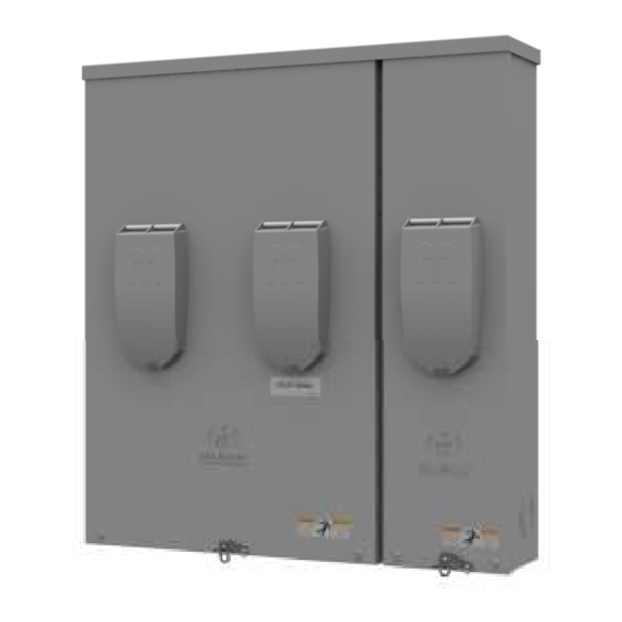
Summary of Contents for MILBANK SYNAPSWITCH MATSCO10011
- Page 1 OWNER’S & INSTALLATION MANUAL MODEL # Revision 1.0 BOM # 1179957 8.19.15 Milbank | 4801 Deramus Ave., Kansas City, MO 64120 | 877.483.5314 | milbankworks.com...
- Page 2 – without the written permission of Milbank Manufacturing. ORIGINAL INSTRUCTIONS (English): The English version of this manual controls over any error in or conflicting interpretation of any translation. Milbank SynapSwitch™ Owner’s and Installation Manual...
-
Page 3: Table Of Contents
REPLACEMENT PARTS ..............................19 REPLACEMENT PARTS IDENTIFICATION ...................... 19 SPECIFICATIONS ..............................20 SPECIFICATIONS ............................. 20 WARRANTY ................................21 MILBANK MANUFACTURING SYNAPSWITCH™ OWNER WARRANTY POLICY ......... 21 Limited Warranty ............................21 Warranty Period ............................21 Warranty Registration Process........................21 About Our Warranty ............................. 21... -
Page 4: Introduction
INTRODUCTION Thank you for your purchase of a Milbank SynapSwitch™ CONTACT INFORMATION Automatic Transfer Switch. This product is designed for There are several ways to contact us for answers to use with standby generators. This SynapSwitch™ may questions you may have about your product. Contact... -
Page 5: Safety
You must also make sure that the procedure, work method or operating technique that you choose does not render the equipment unsafe. Milbank SynapSwitch™ Owner’s and Installation Manual... -
Page 6: Safety Labels
• If you must work around a unit while it is operating, stand on an insulated dry surface to Figure 1 – Milbank PN 1165023 reduce shock hazard. • Do not allow unqualified persons or children to GENERAL SAFETY service equipment. -
Page 7: Operation And Installation
Guidelines for mounting the unit include: document. • Ensure that the mounting surface can support the The Milbank SynapSwitch™ is suitable for use with weight of the SynapSwitch™ and adheres to all local Auto Mains Failure, or 2- or 3-wire-start generators. - Page 8 OPERATION AND INSTALLATION Figure 2 – SynapSwitch™ Schematic/Connection Diagram Milbank SynapSwitch™ Owner’s and Installation Manual...
-
Page 9: Installation
OPERATION AND INSTALLATION INSTALLATION Each installation is unique and it is impossible for Milbank Manufacturing to understand the circumstances in which installation may be achieved. Neither could we know of possible hazards and/or the result of each method or procedure. See Figure 3 for a typical basic install; see Figure 4 for a typical full install. - Page 10 OPERATION AND INSTALLATION Figure 5 – Mounting Dimensions Milbank SynapSwitch™ Owner’s and Installation Manual...
-
Page 11: End User Responsibilities
SynapSwitch™ to prevent generator overload. The All installations of Milbank systems must comply with all purpose of a SynapSwitch™ is to serve as a means of applicable codes, industry standards, and regulations. - Page 12 See Table 1 for examples of settings. Table 1 20kW 12kW 17kW Top switch 10kW setting Bottom switch 1kW setting NOTICE Settings need to be set correctly; press “RESET” after making any changes. Milbank SynapSwitch™ Owner’s and Installation Manual...
-
Page 13: Configuring The Dual In-Line (Dip) Switches
RESET button on the control board. Factory settings for the dual in-line (DIP) switches are set at OFF. The DIP switches on the Milbank SynapSwitch™ Control PCB configure the SynapSwitch™ to operate in different power situations. Each switch has two positions: ON and OFF, as shown in Figure 7. -
Page 14: Push Button Switches
LED Activity The push button switches are used to initialize or The SynapSwitch™ has four LEDs that indicate reset the programmable functions of the Milbank operation of the SynapSwitch™ controller. Note that all SynapSwitch™ and are located around the DIP switch LEDs are bicolor, so if an LED is on, it may be green, control. -
Page 15: Ac Control Interface
Note Green green and yellow are normally connected together with fan in auto mode Heat (gas burner, oil burner, White electric heat) Diagram Courtesy of Honeywell, Inc. Milbank SynapSwitch™ Owner’s and Installation Manual... - Page 16 If the installer tries to initiate a generator exercise test or set a weekly exercise time for a utility-sense generator, this is not possible, so the LEDs will flash red rapidly for 3 seconds. Milbank SynapSwitch™ Owner’s and Installation Manual...
-
Page 17: Testing
Once a year, have a licensed electrician clean the inside of the SynapSwitch™ and inspect for: • Damage or loose parts • Discoloration of wire insulation or components Milbank SynapSwitch™ Owner’s and Installation Manual... -
Page 18: Troubleshooting
• Reorient or relocate the receiving antenna. • Increase the separation between the equipment and the receiver. Milbank SynapSwitch™ Owner’s and Installation Manual... -
Page 19: Replacement Parts
REPLACEMENT PARTS REPLACEMENT PARTS IDENTIFICATION For replacement parts, reference the Milbank part number shown. Figure 13 – Replacement Parts Milbank SynapSwitch™ Owner’s and Installation Manual... -
Page 20: Specifications
29.0 x 24.3 x 8.0 in. (73.7 x 61.7 x 20.3 cm) Weight 42 lb (19 kg) Shipping weight 48 lb (22 kg) * For questions on compatibility with other Milbank generators, please call Milbank sales office at (816) 410-7346. Milbank SynapSwitch™ Owner’s and Installation Manual... -
Page 21: Warranty
WARRANTY POLICY LIMITED WARRANTY Milbank Manufacturing will repair or replace, free of charge, any part(s) of the equipment that is defective in material or workmanship or both providing that installation of the equipment complies with all applicable codes, industry standards, laws, regulations and provided installation manual. Milbank’s SynapSwitch™ and associated components shall be installed only by a licensed electrical contractor, and otherwise this warranty is void. - Page 22 Also excluded is used, reconditioned, and demonstration equipment. The warranty shall not apply to any materials or parts thereof furnished by the Buyer, or acquired from others at the Buyer’s request and/or the Buyer’s specifications or designs. Milbank SynapSwitch™ Owner’s and Installation Manual...
- Page 23 THIS PAGE INTENTIONALLY LEFT BLANK...
- Page 24 Revision 1.0 BOM # 1179957 8.19.15 Milbank | 4801 Deramus Ave., Kansas City, MO 64120 | 877.483.5314 | milbankworks.com...

Need help?
Do you have a question about the SYNAPSWITCH MATSCO10011 and is the answer not in the manual?
Questions and answers