
Summary of Contents for Fabdec Dari-Kool 720012
- Page 1 2016 Installation and Operation Manual Control for milk cooling tanks COMPACT-KOOL...
-
Page 2: Table Of Contents
Contents Function ......... Page 3 Intended use . -
Page 3: Function
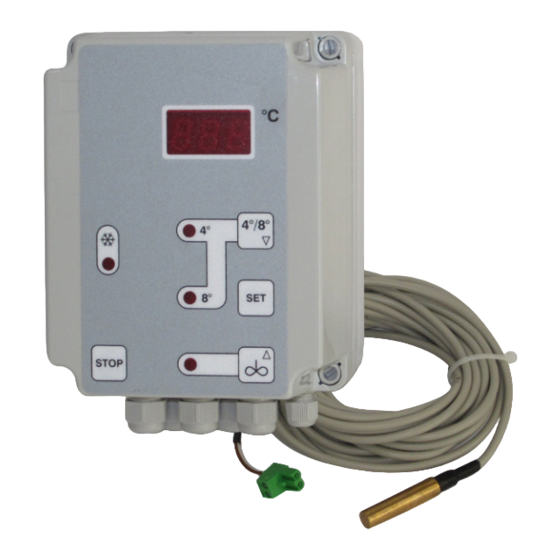
Function This control is a complete control cabinet for milkcooling tanks. The integrated microprocessor regulator with automatic afterstirring has separate relay contacts for the compressor contactor and the stirrer. The measured milk temperature is shown constantly on the display, when the cooling mode is switched on. -
Page 4: Intended Use
Intended use These operating instructions contain important technical and safety information. Please read carefully before instal- lation and before any work on or with the regulator. The control cabinet for milk cooling tanks is used to control the stirrer motors and cooling compressors of milk-cooling systems. Any other use of the device is permissible only with the manufacturer's written consent. -
Page 5: Installation
Installation Installation of housing To secure the housing, proceed as follows: Drill holes as shown in the diagram, insert rawlplugs if necessary. Unfasten the four plastic closure screws and remove the housing top. Screw the housing bottom into place. Position the electrical wiring and sensor connection in accordance with the following instructions. -
Page 6: Housing Dimensions And Technical Data
Housing dimensions and Operating voltage see version: technical data - 230V AC +N +PE, 50/60 Hz - 400V AC +N +PE, 50/60 Hz - 230V AC +N +PE, 50/60 Hz with screw terminals, or when fitted with switching contactor - 400V AC +N +PE, 50/60 Hz °C with switching contactor and motor protection switch... -
Page 7: Operation
Operation The control cabinet is operated at three levels: Working level ... for everyday operation by the end user. °C When cooling mode is active, the milk temperature as currently measured is permanently displayed. The working level also contains the functions: 4°/8°... -
Page 8: Parameter Settings In General
Parameter settings in To adjust a parameter, proceed as follows: general Select parameter. Hold button SET down during the adjustment operation. Use button Arrow UP or Arrow DOWN to set the required value. NB: Holding buttons longer changes the value more quickly. Release button SET. -
Page 9: Working Level Operation
Working level operation The working level is for day-to-day milk cooling operation. When the cooling mode is active, the display continuously shows the current milk temperature. Function LED "4°" shows that target temperature setting for "T1" is active °C LED "8°" shows that target temperature setting for "T2"... -
Page 10: Programming Level Operation
Programming level The programming level is for setting the regulatory parameters. Access to this level is more complex in order to avoid accidental operation resetting of the values by the end user. 4°/8° Switching to programming level: 4° Press button Arrow UP and Arrow DOWN simultaneously for approx. -
Page 11: Configuration Level Operation
Configuration level This level is for configuring the regulator's basic functions. operation To prevent interference by the end user, access is made even more complex. 4°/8° 4° Switching to configuration level: Press button Arrow UP and Arrow DOWN 8° simultaneously for approx. 5 seconds. The first parameter [C1] appears in the display. - Page 12 Parameter P30: Limit for hysteresis T1 downwards Parameter P31: Limit for hysteresis T1 upwards Parameter P32: Limit for hysteresis T2 downwards Parameter P33: Limit for hysteresis T2 upwards Setting of input limits for hysteresis at programming level. Range: 0 .. 99 K Parameter P70: Minimum action time for compressor K1 Setting of minimum action time for compressor relay contacts K1, in order to prevent repeated switching on and off.
-
Page 13: Intermediate Stirring Options During Cooling
Intermediate stirring The control cabinet has a function allowing the agitator to be switched on manually. This can be done is different ways. options during cooling Regardless of the option chosen, the corresponding LED always indicates when the agitator is operating. The function is set at configuration level using parameter [P81]. -
Page 14: Setting The Actual Value Correction
Setting the actual A correction can be made to the value as measured by the sensor, which applies cumulatively over the entire measuring range. value correction This is necessary when: - the length of the sensor cable is changed, or - a faulty sensor is replaced, giving rise to an incorrect reading. -
Page 15: General Measures When Using Electronic Control Systems
General measures when So that even complicated regulatory tasks can be presented to the user using electronic control in a manner which is clear and simple and ensures high measurement accuracy, today's electronic control systems make increasing use of systems microprocessors. - Page 16 If specific interference sources cannot be avoided, they should at least be kept at a distance from the regulator system. Capacitive and inductive couplings can cause crosstalk between high- voltage lines and parallel low-voltage and sensor lines. This distorts measured values and signals and can disrupt the entire regulatory process.
-
Page 17: Guarantee
Semiconductor switches such as thyristors or triacs also produce interference voltages. They occur as a result of non-linear characteris- tics and finite ignition voltages. These components must be protected against excessive voltages, for which mainly varistors, RC combina- tions or choke coils are used. The use of zero-voltage switches is also recommended. -
Page 18: Circuit Diagramm Without Engineprotect (Xx-1)
Fabdec Ltd Fabdec GmbH Fabdec LLC Grange Road Gerhardstrasse 5 October Embankment 12, building 2 Ellesmere 45892 Gelsenkirchen 193091 Saint Petersburg Shropshire Germany Russia SY12 9DG Tel: +44 (0) 1691 627200 Tel: + 49 (0) 209 700 900 Tel: + 7 812 715 0102...
Need help?
Do you have a question about the Dari-Kool 720012 and is the answer not in the manual?
Questions and answers