Table of Contents
Advertisement
Quick Links
2G / 4G – StarLink TrackerSF
Installation Manual
Release 1.1
© Copyright 2017 by ERM Electronic Systems Ltd.
Revision updates log:
Revision
Change
1.0
First version
1.1
Version Update
1.2
Version Update
16 Hasar Shapira St. Rishon LeZion, 75704 Israel | Phone: 972-3-9413313 Fax: 972-3-9413330
http://ermtelematics.com
ERM Electronic Systems LTD
|
info@ermtelematics.com
Date
07/05/2017
25/02/2018
19/0
/ 5
2019
Advertisement
Table of Contents

Summary of Contents for ERM 2G-StarLink TrackerSF
- Page 1 2G / 4G – StarLink TrackerSF Installation Manual Release 1.1 © Copyright 2017 by ERM Electronic Systems Ltd. Revision updates log: Revision Change Date First version 07/05/2017 Version Update 25/02/2018 Version Update 19/0 2019 ERM Electronic Systems LTD 16 Hasar Shapira St. Rishon LeZion, 75704 Israel | Phone: 972-3-9413313 Fax: 972-3-9413330 http://ermtelematics.com...
-
Page 2: Table Of Contents
5.1 Know the StarLink Family of Tracking Devices 5.2 Positioning StarLink Devices in the vehicle 5.2.1 General Installation Instructions 5.2.2 StarLink Location for Optimal Reception Quality 6. S ONFIGURATION 6.1 USB Adapter 6.2 USB Driver ERM CONTACT INFORMATION ERM Advanced Telematics page: 2... -
Page 3: The Starlink 2G / 4G
• Install ERM devices away from any heat sources. • Do not install ERM devices in the engine compartment or on the vehicle’s exterior. • Install ERM devices away from large metallic bodies and never install them in small gaps between metallic objects. -
Page 4: General Instructions
Strip the ends of the wires to be soldered together. Slide an appropriate length of heat-shrink insulation tubing on to one of the wires. Solder the wires. Slide the heat-shrink insulation over the solder joint. ERM Advanced Telematics page: 4... - Page 5 Use a heater-gun to heat the insulation. The insulation shrinks until it sits snugly on the solder joint. Tie the wire with a cable tie in such a way as to relieve stress from the new solder joint. ERM Advanced Telematics page: 5...
-
Page 6: Tools And Equipment/Materials Required
Combination plier Terminal crimper Digital multi-meter Hand torch Cordless drill Gas soldering iron Long-nosed plier Solder Utility knife Wire lugs with star washers T-type nut drivers Plastic tubing Isolation shrink Insulation tape wrap tubing Screwdriver bits ERM Advanced Telematics page: 6... -
Page 7: Installing Starlink Devices
Before beginning installation, make sure your package includes all the following: Strips 3A fuse 3A fuse housing StarLink device StarLink harness Two-sided sticky tape Two-sided sticky paper This procedure describes the standard connections required to operate StarLink devices. ERM Advanced Telematics page: 7... -
Page 8: Know The Starlink Family Of Tracking Devices
Connect the black wire (pin #5) to the vehicle chassis or any grounded part of the vehicle (GND). Make sure the connection is free of paint or dirt to assure a good conductive ground connection Connect the green wire (pin #2) to the vehicle Ignition switch (IGN). ERM Advanced Telematics page: 8... - Page 9 Slide the SIM card into the SIM slot and gently push it in (note the SIM polarity). • Use a screwdriver to push and lock the SIM card in place. • Replace the cover of the SIM slot. ERM Advanced Telematics page: 9...
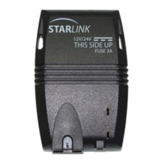
- Page 10 (note the THIS SIDE UP label) with a double-sided adhesive sticker or with the cable ties threaded through the device side slits. (as shown on the next page). Reassemble any vehicle components you may have dismantled. ERM Advanced Telematics page: 10...
-
Page 11: Positioning Starlink Devices In The Vehicle
If necessary, dismantle vehicle components to gain access to the selected concealed location. Place the device in the selected location but do not affix it yet. The StarLink device should be installed horizontally, with its LEDs facing towards the sky. ERM Advanced Telematics page: 11... - Page 12 Never install the StarLink device with the antenna side next to metal objects. • The StarLink device must be installed by qualified service personnel only. • All wires must be isolated after installation. • The following figure shows an example of a good installation position: ERM Advanced Telematics page: 12...
-
Page 13: Starlink Configuration
USB Adaptor module Power and eNet cable Ignition cable eNet spare cable Using the eNet cable, connect the eNet hub to the USB Adapter, then connect the other end to the eNet hub: ERM Advanced Telematics page: 13... - Page 14 Connect the USB cable to the USB Adapter Connect the power supply: Connect one side of the power cable to Use the red and black wires for the power the eNet hub supply (see section 5) ERM Advanced Telematics page: 14...
- Page 15 Turn “on” the power supply and verify that the StarLink red LED begins blinking after a few seconds. You are now ready to configure your StarLink device. Connect the USB cable to your PC and install the USB DRIVER as described in the following paragraph: ERM Advanced Telematics page: 15...
-
Page 16: Usb Driver
StarLink TrackerSF Installation Manual USB Driver Use your ERM username (given by ERM support) and password to enter the ERM Portal at: http://erm.co.il/protocol Go to the Tools link at the lower left. Click the USB Driver link, download the tool to your computer and install For the full installation instructions please refer to the tutorials session on ERM’s YouTube Channel using the following link:... - Page 17 FCC Statement This device complies with part 15 of the FCC rules. Operation is subject to the following two conditions: (1) this device may not cause harmful interference, and (2) this device must accept any interference received, including interference that may cause undesired operation. Changes or modifications not expressly approved by the party responsible for compliance could void the user's authority to operate the equipment.

Need help?
Do you have a question about the 2G-StarLink TrackerSF and is the answer not in the manual?
Questions and answers