
Subscribe to Our Youtube Channel
Related Manuals for Cetetherm AquaEfficiency EFF76 DD

Summary of Contents for Cetetherm AquaEfficiency EFF76 DD
- Page 1 Cetetherm AquaEfficiency Installation, service and operating instruction Installation, service and operating instruction Doc-1388 1810...
- Page 2 This manual is published by Cetetherm. Cetetherm can without further notice make changes and improvements to the content in this manual if it is necessary due to printing mistakes, wrong information or changes in the hardware or software. All these types of changes will be included in future release of the...
-
Page 3: Table Of Contents
Cetetherm AquaEfficiency Installation, service and operating instruction Contents General ..........................4 Product overview AquaEfficiency ......................4 Operating principle ....................... 5 Installation of an AquaEfficiency unit ................. 6 Unpacking/preparation/mounting ......................6 Commissioning ............................6 Flowcharts ..........................7 Installation of an AquaEfficiency Direct unit ....................7 4.1.1... - Page 4 Cetetherm AquaEfficiency Installation, service and operating instruction 11.1 Login ............................... 34 11.2 The technician Main menu ........................34 11.3 Configuration menu ..........................35 11.4 S1 Menu Secondary Outlet ........................36 11.5 Sensor 2 menu, secondary inlet temperature sensor ................36 Delta T (S3-S2) Menu “Efficiency”......................
- Page 5 Exploded views and spare part list ..................77 20.1 EFF52/EFB60 ............................77 20.2 EFF76/EFB112 ............................78 20.3 EFP All models ............................79 Commissioning report ......................80 Declaration of conformity ....................81 Warranty ..........................82 23.1 How to contact Cetetherm ........................82...
-
Page 6: General
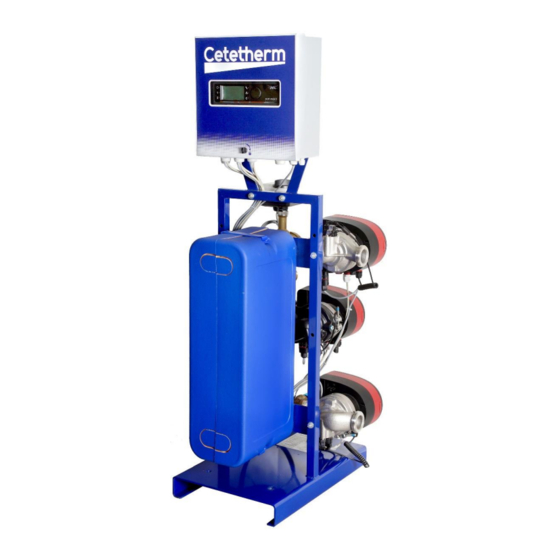
Installation, service and operating instruction General Cetetherm AquaEfficiency is a compact tap water system product including a heat exchanger, motorised control valve and managed primary and secondary pumps, as per versions. It is equipped with a control box including a dedicated PCB and communicant temperature controller. Piping is made of specially designed steel and brass parts. -
Page 7: Operating Principle
Cetetherm AquaEfficiency Installation, service and operating instruction Operating principle AquaEfficiency EFF76 / EFB112 DD AquaEfficiency EFP 5000/7000 DD • 8The primary water enters the control valve with actuator (A) and leaves through the fitting (B). • Cold water enters at bottom part (CW) and leaves at the required temperature at high part (DHW). -
Page 8: Installation Of An Aquaefficiency Unit
Cetetherm AquaEfficiency Installation, service and operating instruction Installation of an AquaEfficiency unit The installation work must be carried out by an authorized installation contractor. The temperature and the pressure of the water are very high. Only qualified technicians are allowed to work with the AquaEfficiency. -
Page 9: Flowcharts
25% to 100% of the nominal secondary pump signal, to stick to the actual demand. Cetetherm do not recommend the use of a mixing bottle on primary side of an AquaEfficiency installation, because the mixing effect destroys the low return temperature. But the need for the differential pressure breaker functionality of this mixing bottle is still mandatory. -
Page 10: Example Of Flowchart With Eventual Optimised Use Of Primary Vessel
Cetetherm AquaEfficiency Installation, service and operating instruction 4.1.2 Example of Flowchart with eventual optimised use of primary vessel 4.1.3 Other possible drawing Not recommended for low return temperature applications. Installation of an AquaEfficiency Indirect unit (Semi Instantaneous) NAME NAME Primary inlet... -
Page 11: Standard Flowchart For Indirect Version
Cetetherm AquaEfficiency Installation, service and operating instruction 4.2.1 Standard flowchart for Indirect version 4.2.2 Other possible drawing Not recommended for low return temperature applications. -
Page 12: Installation Of An Alfapilot Unit
Cetetherm AquaEfficiency Installation, service and operating instruction Installation of an AlfaPilot unit Operating principle AlfaPilot AlfaPilot is a simple and reliable system based on comparative measure of primary return, S3, and primary storage vessel temperature, Pt1. AlfaPilot acts as a “piston” effect on the primary storage vessel allowing fulfilling peak demands of Domestic Hot Water. -
Page 13: Alfapilot With Low Return Temperature Heat Transfer Unit
Cetetherm AquaEfficiency Installation, service and operating instruction 5.2.1 AlfaPilot with low return temperature heat transfer unit... -
Page 14: Alfapilot With Double Pass Heat Exchanger Tap Water System
Cetetherm AquaEfficiency Installation, service and operating instruction 5.2.2 AlfaPilot with double pass heat exchanger tap water system... -
Page 15: Alfapilot With Low Return Temperature Tap Water Unit
Cetetherm AquaEfficiency Installation, service and operating instruction 5.2.3 AlfaPilot with low return temperature tap water unit Not recommended on solar installations when recycling flow rates is too high on DHW side (hospitals for example). -
Page 16: Installation Of A Solarflow Unit
Cetetherm AquaEfficiency Installation, service and operating instruction Installation of a Solarflow unit Operating principle Solarflow In the flowchart RS means a renewable source, eg solar, heat pump, condensate or else recover unit. The 3-port mixing valve is activated only if temperature in STP or RS is hot enough, to limit DHW over heating on S1. -
Page 17: Measure Sketches
Cetetherm AquaEfficiency Installation, service and operating instruction Measure sketches AquaEfficiency EFB60/EFF52 ID, Direct Version (Instantaneous) -
Page 18: Aquaefficiency Efb112/Eff76 Id, Direct Version (Instantaneous)
Cetetherm AquaEfficiency Installation, service and operating instruction AquaEfficiency EFB112/EFF76 ID, Direct Version (Instantaneous) -
Page 19: Aquaefficiency Efp3000 Id, Direct Version (Instantaneous)
Cetetherm AquaEfficiency Installation, service and operating instruction AquaEfficiency EFP3000 ID, Direct Version (Instantaneous) -
Page 20: Aquaefficiency Efp5000/7000 Id, Direct Version (Instantaneous)
Cetetherm AquaEfficiency Installation, service and operating instruction AquaEfficiency EFP5000/7000 ID, Direct Version (Instantaneous) -
Page 21: Aquaefficiency Efp9000 Id, Direct Version (Instantaneous)
Cetetherm AquaEfficiency Installation, service and operating instruction AquaEfficiency EFP9000 ID, Direct Version (Instantaneous) -
Page 22: Aquaefficiency Efb60/Eff52 Dd, Indirect Version (Semi-Instantaneous)
Cetetherm AquaEfficiency Installation, service and operating instruction AquaEfficiency EFB60/EFF52 DD, Indirect Version (Semi-Instantaneous) -
Page 23: Aquaefficiency Efb112/Eff76 Dd, Indirect Version (Semi-Instantaneous)
Cetetherm AquaEfficiency Installation, service and operating instruction AquaEfficiency EFB112/EFF76 DD, Indirect Version (Semi-Instantaneous) -
Page 24: Aquaefficiency Efp3000 Dd, Indirect Version (Semi-Instantaneous)
Cetetherm AquaEfficiency Installation, service and operating instruction AquaEfficiency EFP3000 DD, Indirect Version (Semi-Instantaneous) -
Page 25: Aquaefficiency Efp5000/7000 Dd, Indirect Version (Semi-Instantaneous)
Cetetherm AquaEfficiency Installation, service and operating instruction AquaEfficiency EFP5000/7000 DD, Indirect Version (Semi-Instantaneous) -
Page 26: Aquaefficiency Efp9000 Dd, Indirect Version (Semi-Instantaneous)
Cetetherm AquaEfficiency Installation, service and operating instruction 7.10 AquaEfficiency EFP9000 DD, Indirect Version (Semi-Instantaneous) -
Page 27: Electrical Installation
Cetetherm AquaEfficiency Installation, service and operating instruction Electrical installation Power supply the control box with 230VAC 50 Hz. The control box with the controller Micro 3000 is called the secondary control box. Human differential protection and protection against short circuits and protection over intensity must be installed in the main electric box. -
Page 28: Electrical Wiring Diagram
Cetetherm AquaEfficiency Installation, service and operating instruction Electrical wiring diagram ModBus terminal Power terminal I/O terminal 8.2.1 ModBus terminal ModBus *) cable shield 8.2.2 Power terminal 230V output to pumps and valves ╧ ╧ ╧ ╧ ╧ Main power Pump1... -
Page 29: I/O Terminal
Cetetherm AquaEfficiency Installation, service and operating instruction 8.2.3 I/O terminal IPSO 1 On/Off 0/10V IPSO 1 On/Off 0/10V Pump 1/Pompe 1 Pump 3/Pompe 3 24Vac Sensor Pt1 Relay 1 Actuator Sensor 1 Sensor 2 Sensor 3 Sensor 4 IPSO 1... -
Page 30: User Instruction Operator Control Panel Micro 3000
Cetetherm AquaEfficiency Installation, service and operating instruction User instruction operator control panel Micro 3000 Wheel/Button Status LED Button Function Rotary button, wheel, for scrolling through the menus. Access sub-menus and change settings by pressing it. To activate the line or change a highlighted value, simply press the wheel. -
Page 31: Home Screen
Cetetherm AquaEfficiency Installation, service and operating instruction Home screen When starting up the Micro 3000 controller this menu displays on them screen. The menu is called the Home screen. Date / hour Access level: Locked=restricted Key= total (3333) DHW temperature... -
Page 32: Setting The Time And Date
Cetetherm AquaEfficiency Installation, service and operating instruction Setting the time and date 1. Turn the wheel anticlockwise to highlight the line with time and date at the top of the screen. Press the wheel to enter the Date/Time menu. 2. Press the wheel to change the first variable, the year. -
Page 33: End User Mode
(UTD, Standards EN, ISO etc.) All countries have different rules for how hot or cold tap water should be. Cetetherm recommends the hot water temperature is at least 55°C and a hot water circulation not less than 50°C. At a temperature below 50°C there is a risk of bacterial growth on collective installation. -
Page 34: Changing Time And Temperature In A Time Program
Cetetherm AquaEfficiency Installation, service and operating instruction 10.3 Changing time and temperature in a time program By default the DHW set point SP_T_Sec_Outlet, set to 60°C by default, at any time, all the days of the week. Add extra temperature set points at different times of the day. -
Page 35: Making A Quick Temperature Change
It is possible to quickly define a “one time” temperature change, a period of the day with a different setting. When the change period has expired, the temperature set point goes back to standard time schedule program. NOTE: Cetetherm do not recommend this in our application. 1. In the home-screen, use the wheel and mark the hourglass. Press the wheel. -
Page 36: Technician Menu, Total Read And Write Level
Cetetherm AquaEfficiency Installation, service and operating instruction Technician menu, total read and write level In the technician menu you can: • make settings for the secondary outlet temperature • enable/disable functions like Eco, booster, thermal treatment • enable/disable the fouling function (option) •... -
Page 37: Configuration Menu
Cetetherm AquaEfficiency Installation, service and operating instruction 11.3 Configuration menu Remark: After resetting the controller, this sub menu should be accessed to configure pumps’ number. Parameter Factory Optional setting Description Default Setting Type 0=First 1=EFF 0= Aqua First Set to 1... -
Page 38: S1 Menu Secondary Outlet
Cetetherm AquaEfficiency Installation, service and operating instruction 11.4 S1 Menu Secondary Outlet S1 is the master sensor. Parameter Factory Optional setting Description Default Setting SP_T_Sec_Outlet 60°C DHW Setpoint Change setpoint value in clock program Delta T S1 HiAlm 10°C 0-50 High Temperature Alarm if Ts1 >... -
Page 39: Delta T (S3-S2) Menu "Efficiency
Cetetherm AquaEfficiency Installation, service and operating instruction Parameter Factory Optional setting Description Default Setting 3…20 DeltaTS1S2 SpdP3P4 8°C When the value S1-S2 is below 8° the signal sent to charging pump start to reduce. 4…20 P band DT(S1-S2) 5°C Proportional value of the control... -
Page 40: S5 Menu Outdoor Temperature
Now if setting an ambient temperature to 15°C, the set point will be decreased to ≈87°C. If no outdoor temperature sensor (S5) is in use, Cetetherm strongly recommend to manually entering a value of 20°C for the S5 sensor. The S5 value needs to be set for not disturbing the constant temperature set point on Pt2 sensor (see 11.14 Solar... -
Page 41: Thermal Treatment Menu
Cetetherm AquaEfficiency Installation, service and operating instruction Application Heat curve Heatcurve curvature Slope Floor heating Radiators Convectors 1.4 à 1.6 11.9 Thermal Treatment Menu The function Thermal Treatment is disabled by default. Activate it by setting TrTh_Activated to ON. The clock program logically activates it automatically or not. -
Page 42: Safety Function
Cetetherm AquaEfficiency Installation, service and operating instruction 11.10 Safety Function This function activates the pumps' power relays at the same time without considering ipsothermic contacts' inputs. NOTE: This function can be enabled from end user level. Parameter Factory Default Setting... -
Page 43: Fouling Function
Cetetherm AquaEfficiency Installation, service and operating instruction 11.12 Fouling function Accessing the fouling-menu requires login at Technician level. Fouling function can be activated when the sensor S3 is connected. If the temperature in S3 is too high for a long time this function activates an alarm that consider the heat exchanger fouled. -
Page 44: Solar Menu
Cetetherm AquaEfficiency Installation, service and operating instruction 11.14 Solar menu AquaEfficiency can be acting with a SolarFlow or AlfaPilot working mode, allowing taking benefit of a solar energy with primary storage tank installation or alternative energy recovering installation. The Micro 3000 combined with extra sensors can pilot a second 0-10V signal valve actuator, allowing directing the outlet primary flow towards the primary storage vessel or towards the boiler (or heat generator). -
Page 45: 230V Triac Menu
Cetetherm AquaEfficiency Installation, service and operating instruction 11.15 230V Triac menu Accessing the Triac-menu requires login at Technician level. Choose between one of two different operating modes. NOTE: both modes cannot be combined. • Pulse(s) function Clock pulse, using time program. Pulse duration settable. -
Page 46: Autotest Menu
Cetetherm AquaEfficiency Installation, service and operating instruction 11.16 Autotest menu Accessing the Autotest menu requires login at Technician level. This submenu allows testing analog (contacts) and digital (0-10V) outputs that manage pumps start/stop, both programmable relays, 230V Triac output, pumps’ speeds and valves’ signals. It is possible to run an automatic sequence or to test manually each output individually. -
Page 47: Clear Alarm Menu
Cetetherm AquaEfficiency Installation, service and operating instruction The Auto test sequence described in the picture is a general test procedure. It may vary depending on connected components. NOTE: A pump fault may occur after Auto test. In this case, clear the alarm according to 11.17 Clear alarm menu. -
Page 48: Service Menu
Cetetherm AquaEfficiency Installation, service and operating instruction Service Menu Press the key to enter the Service menu. In the service menu you can: • change password for technician level • trending parameters • display the trend buffer • check operating hours. -
Page 49: Menu Continue
Cetetherm AquaEfficiency Installation, service and operating instruction 12.3 Menu Continue Menu Sub-menu Sub-menu Sub-menu Description Continue Operating hours Viewing operating hours of internal parameters Trending Points in trend Select variables to trend for example temperature sensors Display Trend buffer View the records... -
Page 50: Operating Hours
Cetetherm AquaEfficiency Installation, service and operating instruction 12.4 Operating hours Operating hours for the following parameters can be checked: • • Cmd_Distant Triac_Output • • Therm_Protec_P1/P2/P3/P4 AFF_leg_active • • Cmd_P1/P2/P3/P4 Multi_P • • SAFETY_FCT • • Booster Tank load •... -
Page 51: Trending Parameters
Cetetherm AquaEfficiency Installation, service and operating instruction 12.5 Trending parameters A lot of different variables can be recorded or trended. It can be temperatures’ measurement, valves or pumps’ signals, ipsothermic contacts, alarms, thermal treatments etc. 1. Press key to access to Service Menu, then click on “Continue. -
Page 52: Display The Trend Buffer
Cetetherm AquaEfficiency Installation, service and operating instruction 12.5.1 Display the trend buffer key to access to Service Menu, then click on “Continue”. 1. Press 2. Select “Trending” in the menu. 3. Select “Display Trend Buffer”. 4. Select the variable to display, S1 in this case, and press the wheel. -
Page 53: Alarm Menu
Cetetherm AquaEfficiency Installation, service and operating instruction Alarm menu Contact Relays 1 and 2 are volt Free Contacts (VFCs), 2 Amps maxi, each under 230 V. Press key to access to Alarm menu. The menu contains four different lists: •... -
Page 54: Parameter List
Cetetherm AquaEfficiency Installation, service and operating instruction Parameter list There are more than 100 different parameters used in the controller. Most of them are used for internal programs and calculations. Here we describe the main points. Name Description Unit Modbus... -
Page 55: Factory Reset
Cetetherm AquaEfficiency Installation, service and operating instruction Factory RESET After a reset must the controller be re-configured, see 11.3 Configuration menu. Especially the number of pumps must be configured. 1. Press both for 5 seconds. 2. Rotate the wheel; select the last line, program name with a star at the end. -
Page 56: Modbus
Cetetherm AquaEfficiency Installation, service and operating instruction Modbus 16.1 Modbus communication The controller includes a Modbus slave communication protocol, type ModBus RTU RS485. Connection between BMS (building management system) and Micro 3000 requires two polarized wires on C+ and C-, respectively labelled 25 and 26 on controller C Bus terminal. -
Page 57: Change Modbus Parameters
Cetetherm AquaEfficiency Installation, service and operating instruction 16.3 Change Modbus parameters key to access to Service Menu, go to “Login Installer”, 1. Press press the wheel. 2. Enter the current password, press the wheel to validate. 3. Mark “Next" then press the wheel. -
Page 58: Modbus Slave Communication Parameters
Cetetherm AquaEfficiency Installation, service and operating instruction 16.4 Modbus slave communication parameters MODBUS Speed / Vitesse : 9600 In case of multiple controllers, change ModBus controler slave number Bit number / Nbre de bits :* Parameter="DEVICE ID" Stop bit / Bit de stop : Parity / Parité... -
Page 59: Trouble Shooting
Cetetherm AquaEfficiency Installation, service and operating instruction Trouble shooting FINDINGS PROBABLE CAUSES REMEDIES Pump not operating Locked rotor or damaged Force to rotate. Replace if required Corresponding led is not lit Replace Power Board Pump relay damaged Replace Power Board... -
Page 60: Maintenance And Repairs
CIP option (F/B series only). Only replace any defective parts with the original spare parts. Please contact your Cetetherm distributor for spare parts, note serial number and model designation. Maintenance work must be carried out by a qualified and authorized technician. -
Page 61: Clean The Plate Heat Exchangers (P-Series)
9. Tighten up the exchanger, using the tightening length as initially. 10. Make sure the thermometer pocket of the control sensor is also cleaned properly. Ask the local Cetetherm Company for more information on maintenance procedures, disassembly, cleaning, remounting. Plates’ package thickness PHE in between frames... -
Page 62: Open The Control Box
Cetetherm recommends the use of a pre-fitted Cetetherm CIP 20-type cleaning unit together with a specific cleaning agent, such as AlfaPhos that is environmentally friendly. There are several product solutions available depending on the cleaning job to be tackled. Use a neutralizing solution, such as AlfaNeutra, before rinsing. -
Page 63: Change Fuses
Cetetherm AquaEfficiency Installation, service and operating instruction 18.4 Change fuses The control box is fitted with a set of fuses to protect the different components against overload. Extra fuses are included in the control box. The service work must be carried out by an authorized service technician. -
Page 64: Change Or Add A Pump
Cetetherm AquaEfficiency Installation, service and operating instruction 18.7 Change or add a pump Control that the fuse has the correct size compare to the pump consumption. AquaEfficiency can be equipped with four pumps, fixed or variable. Fix recycling pumps can be connected to a direct AquaEfficiency respecting 230V electrical consumption. -
Page 65: Relays 1 And 2 Wiring
Cetetherm AquaEfficiency Installation, service and operating instruction 5. ON/OFF contact and 0-10V signal wiring ON/OFF Contact Note: No polarity. Must be a potential-free contact. Connection on I/O terminal Connection on Magna 3 pump ╧ Pump 1 Pump 2 Pump 3 Pump 4 Connect to ╧... -
Page 66: Change Or Add An Extra Sensor
Cetetherm AquaEfficiency Installation, service and operating instruction 18.9 Change or add an extra sensor Please see 8.2 Electrical wiring diagram. Temperature sensors are real or simulated thanks to micro switches. The affected sensors are S1-S5, Pt1 & Pt2. If a sensor is not present, corresponding micro switch must be ON. -
Page 67: Add Alfapilot Functionality
Cetetherm AquaEfficiency Installation, service and operating instruction 18.12 Add AlfaPilot functionality NOTE: AlfaPilot was formerly named AlfaStoreB. The AquaEfficiency can work as an AlfaPilot by adding: • Valve #2: control valve • Pt1: temperature sensor • Pt2: surface temperature sensor •... -
Page 68: Alfapilot
Cetetherm AquaEfficiency Installation, service and operating instruction 18.12.2 AlfaPilot This function require: • Valve #2:control valve • Pt1: temperature sensor • Pt2: surface temperature sensor When Pt1>(S3+DT Recov Min) the function is activated and opens the second control valve wired on AO4 output, extra actuator. -
Page 69: Technical Data
Cetetherm AquaEfficiency Installation, service and operating instruction 18.13 Technical data All models are power supplied 230V 50Hz. SECONDARY SIDE PRIMARY SIDE (SS/DS/DD models only) 3 port Valve Imax Pmax Imax Pmax Valve Pump type Pump type Model Magna 3(D) Magna 3... -
Page 70: Pump Settings
Cetetherm AquaEfficiency Installation, service and operating instruction Pump settings Pumps of delivered units have all been factory programmed. This guide is more applicable in case of adding a pump or pump replacement for which it is not set. Button Function Goes to the "Home"... -
Page 71: Set Date And Time
Cetetherm AquaEfficiency Installation, service and operating instruction 19.2 Set date and time 1. Navigate from “Home” to “Settings”. 2. Select the line “General settings”. 3. Press [OK]. 4. Select the line “Set date and time”. 5. Press [OK]. 6. Select the line “Select date format”. -
Page 72: Setting The Pump Control Mode
Cetetherm AquaEfficiency Installation, service and operating instruction 19.3 Setting the pump control mode Note: Cetetherm recommend to use, Constant Curve and with setpoint 100%. 1. Navigate from “Home” to “Assist”. Select the line “Assisted pump setup”. 3. Go to the submenu “Select control mode”. -
Page 73: Settings With Double Pumps
Cetetherm AquaEfficiency Installation, service and operating instruction 19.4 Settings with double pumps 1. Navigate from “Home” to “Assist”. 2. Select the line “Multi-pump setup”. 3. Press [OK]. 4. Go to submenu “Select multi-pump function”. 5. Select the line “No multi-pump function”. -
Page 74: Relay Outputs
Cetetherm AquaEfficiency Installation, service and operating instruction 6. Go to the submenu “Electrical signal”. 7. Select the line “0-10V”. 8. Press [OK] to save the setting. 9. Press to see settings summary. 10. Press [OK] to confirm and enable. 19.6 Relay outputs 1. -
Page 75: Pump Settings
Cetetherm AquaEfficiency Installation, service and operating instruction 19.7 Pump settings 1. Navigate from “Home” to “Settings”. 2. Select the line “Operating mode”. 3. Press [OK]. 4. Select “Normal”. 5. Press [OK] to save the setting. 6. Return to the main menu “Settings”. -
Page 76: Enable/Disable Settings
Cetetherm AquaEfficiency Installation, service and operating instruction Note: The operating mode must be set to "Normal" before a control mode can be enabled. 13. Return the main menu “Settings”. 14. Select the line “Control mode”. 15. Press [OK]. 16. Select ”Constant curve”. -
Page 77: Grundfos Eye Operating Indications
Cetetherm AquaEfficiency Installation, service and operating instruction 19.9 Grundfos Eye operating indications Grundfos Eye Indication Cause Ni lights on Power off Pump not running Two opposite green indicator lights running in Power on. the direction of rotation of the pump. - Page 78 Cetetherm AquaEfficiency Installation, service and operating instruction Warning and alarm Fault Automatic Corrective actions codes reset and restart? Pump communication Communication fault Replace the pump or call GRUNDFOS fault (10) between different parts SERVICE for assistance. Check if the Alarm of the electronics.
-
Page 79: Exploded Views And Spare Part List
Cetetherm AquaEfficiency Installation, service and operating instruction Exploded views and spare part list 20.1 EFF52/EFB60 ARTICLE No. DESCRIPTION KITREG01 Power board for ARMAQ3200 CY9-319+connectors+supply wire REG30910 Controller MICRO 3000 Set FR-GB-DE KITARMAQ3200 KIT ARMAQ3200 control box with bracket + Micro3000 controller... -
Page 80: Eff76/Efb112
Cetetherm AquaEfficiency Installation, service and operating instruction 20.2 EFF76/EFB112 ARTICLE No. DESCRIPTION KITREG01 Power board for ARMAQ3200 CY9-319+connectors+supply wire REG30910 Controller MICRO 3000 Set FR-GB-DE KITARMAQ3200 KIT ARMAQ3200 control box with bracket + Micro3000 controller COF32411 Door for Armafirst cabinet... -
Page 81: Efp All Models
Cetetherm AquaEfficiency Installation, service and operating instruction 20.3 EFP All models ARTICLE No. DESCRIPTION KITREG01 Power board for ARMAQ3200 CY9-319+connectors+supply wire REG30910 Controller MICRO 3000 Set FR-GB-DE KITARMAQ3200 KIT ARMAQ3200 control box with bracket + Micro3000 controller COF32411 Door for Armafirst cabinet... -
Page 82: Commissioning Report
Cetetherm AquaEfficiency Installation, service and operating instruction Commissioning report... -
Page 83: Declaration Of Conformity
Cetetherm AquaEfficiency Installation, service and operating instruction Declaration of conformity... -
Page 84: Warranty
Fitting costs, refitting costs, packaging, transport, and any accessories or equipment not manufactured by Cetetherm, which will only be covered by any warranties issued by said third-party manufacturers. Any damage caused by connection errors, insufficient protection, misapplication or faulty or careless operations.
Need help?
Do you have a question about the AquaEfficiency EFF76 DD and is the answer not in the manual?
Questions and answers