Advertisement
Quick Links
Advertisement

Related Manuals for ETS 9903

Summary of Contents for ETS 9903
- Page 1 CHARGE DEVICE MODEL TEST FIXTURE Model 9903 Operating Manual 10/12...
- Page 2 1.0 INTRODUCTION The rapid advancement in the electronics industry during the past decade has placed an increasing importance on the understanding of electrostatics and its effect on electronic devices and systems. Electrostatic discharge (ESD) is a common cause of microelectronic circuit failure.
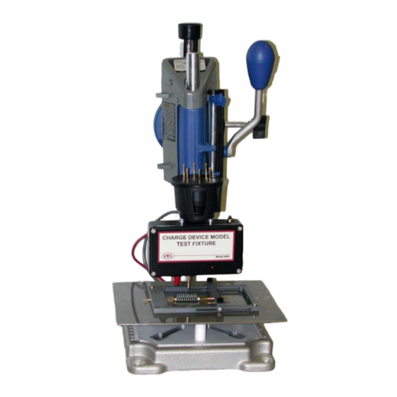
- Page 3 The Model 9903 Charge Device Test Fixture shown in Figure 1.0-1 is a completely integrated unit that provides the means of performing both direct charge and field induced CDM tests. IMPRORTANT NOTE The Model 9903 only provides the means to perform CDM testing. It does not produce verification waveforms that meet all the requirements specified in the test standards referenced above.
- Page 4 400 MegOhm series resistor in the charging circuit. The Model 9903 in conjunction with either the ETS Model 910 with CDM modification or the Model 9910 enables the user to perform both Field Induced and Direct Charge tests.
- Page 5 Figure 2.0-2: DUT Holding Fixture The spring-loaded pins (Interconnect Devices Series S, Size 3) shown in Figure 2.0-3 are interchangeable. Three types are provided. They are round tip (J) for pad terminals, cup tip (G) for DIP style legs, and point tip (B) for very small contact points. Figure 2.0-3: Spring-loaded pin configurations To change pins raise the test head to the top by loosening the lever on the rear.
- Page 6 3.0 SET UP The Model 9903 is designed to work with a minimum 1 GHz/4Gsample oscilloscope with 50 Ohm input. It is connected to the oscilloscope via a 2’ (61cm), 50 Ohm, low loss, semi-rigid cable. System Set Up 3.1.1 Set-Up (Model 910 modified for CDM) Connect the CDM Test Fixture to the Model 910 as shown in Figure 3.0-1.
- Page 7 Figure 3.0-2: Model 9903 with Model 9910 1. Plug the red 0.080” pin plug from the CDM Test fixture into the CDM 0.080 pin jack on the Simulator OUTPUT panel. This provides the voltage to the induction plate or to the device depending on the type of test.
- Page 8 Figure 3.0-4: Direct Charge connections 6.4 Waveform Verification The Model 9903 only provides the means to perform CDM testing. It does not produce verification waveforms that meet all the requirements specified in the test standards referenced above. These deviations are small, but may be outside the limits specified.
- Page 9 ESD STM 5.3, 4pf Disc @ 500V JEDEC JDCS 22-C101E, 6.8pF Disc @ 500V ESD STM 5.3, 30pF Disc @ 500V JEDEC JDCS 22-C101E, 55pF Disc @ 500V Figure 3.0.5a: Typical Field Induce Model verification waveforms...
- Page 10 Figure 3.0-6 lists the waveform requirements for both the ESDA and JEDEC standards. ESD STM 5.3, 4pf Disc @ 500V (Touch disc to charge, remove probe, discharge) JEDEC JDCS 22-C101E, 6.8pF Disc @ 500V (Touch disc to charge, remove probe, discharge) ESD STM 5.3, 4pf Disc @ 500V (Hold disc to charge then discharge) JEDEC JDCS 22-C101E, 6.8pF Disc @ 500V (Hold disc to charge then discharge) Figure 3.0.5a: Typical Direct Charging Method verification waveforms...
- Page 11 a. ANSI/ESD-STM 5.3 b. JEDS22-C101E Figure 3.0-6: ANSI/ESD-STM 5.3 and JEDS22-C101E Waveform requirements...
- Page 12 Adapter limits the voltage to just the low range of 2000V. For the Model 9910, select the CDM function. This limits the voltage to 1000V. Under no circumstances should the Model 9903 be operated above 2000V. This will destroy the timing relays.) Depress and release the Charge button on the Fixture module.
- Page 13 a. 4.0pF Disc 6.8pF Disc Figure 3.0-8: Typical Induced Charge waveforms for small discs 6.4.2 Direct Charge Measurement 1. Configure the Test Fixture for Direct Charge Measurements per Section 3.2.2. 2. Adjust the height of the Press test head so that the ground plane is approximately 0.5”...
-
Page 14: Device Testing
Repeat the measurement at least 2 more times. The waveforms for the 4.0 and 6.8pF discs will look similar those shown in Figure 3.0-9. Record and save the data. 4. Repeat the above procedure for measurements at –500V. 5. Other voltage levels can be used. a. - Page 15 5. For Field Induce charging, depress the Discharge button momentarily, then quickly lower the test head enabling the spring-loaded pin to discharge the DUT. The discharge waveform will be displayed on the scope. Continue to hold the lever down until the red LED indicator goes out.
-
Page 16: Warranty
The buyer is expected to expressly waive rights to any warranty other than that stated herein. ETS must be notified before any equipment is returned for repair. ETS will issue an RMA (Return Material Authorization) number for return of equipment.
Need help?
Do you have a question about the 9903 and is the answer not in the manual?
Questions and answers