Table of Contents
Advertisement
Quick Links
A Member of SHIBUYA Group Companies
Refer all servicing to
qualified personnel.
This manual is written for
qualified mechanics and
electricians who must install or
service the FR-20 or the FR-30
Centrifugal Feeders.
Do not use this manual
with feeders that have
serial numbers lower than
19448, except where noted.
Please copy the feeder's
serial plate information:
Model FR-20 &
FR-30 Centrifugal
Feeders
ANSI/Metric Installation &
Maintenance Manual
Model Number:
Inventory Number (Check One):
FR20XXXDSA
FR20XXXASA
FR20XXXASM
Second Edition, Revision 3. All Rights Reserved.
Copyright © 2005,1996, 1994, 1992 by Shibuya Hoppmann
www.hoppmann.com • email: publications@hoppmann.com
Serial Number/Date:
FR30XXXDSA
FR30XXXASA
FR30XXXASM
13129 Airpark Drive, Suite 120
Elkwood, Virginia 22718
Phone: (540) 829-2564
Toll Free: (800) 368-3582
Fax: (540) 829-1724
Advertisement
Table of Contents

Summary of Contents for Shibuya Hoppmann FR-20
- Page 1 FR30XXXDSA FR20XXXASA FR30XXXASA FR20XXXASM FR30XXXASM Second Edition, Revision 3. All Rights Reserved. Copyright © 2005,1996, 1994, 1992 by Shibuya Hoppmann 13129 Airpark Drive, Suite 120 Elkwood, Virginia 22718 Phone: (540) 829-2564 Toll Free: (800) 368-3582 Fax: (540) 829-1724 www.hoppmann.com • email: publications@hoppmann.com...
- Page 2 About this Manual Assumptions This manual is written for a qualified mechanic or electrician who must install or service the FR-20 or FR-30 feeder. All procedures in this manual should be performed by you or under your direction. This manual covers eight models. If you are unsure which model...
- Page 3 System Operations Manual. Tools You Will Need The model FR-20 and FR-30 feeders are offered in both ANSI and metric versions. For maximum compatibility, ANSI units are classified as “soft ANSI” construction, meaning that metric threads and hardware are used throughout.
-
Page 4: Table Of Contents
Before You Start Feeder Description & Overview of the FR-20 & FR-30 Specifications Figures: Figure 1-1. FR-20 & FR-30 Feeder Exploded View Figure 1-2. FR-20 Feeder Specifications Figure 1-3. FR-30 Feeder Specifications Safety Precautions Safety Precautions Operating & Maintenance: Do's & Don'ts Installation &... - Page 5 Figure 5-4. Older Style Backup Ring Figure 5-5. Current Style Backup Ring Figure 5-6. Machinable Bowl Surfaces Figure 5-7. FR-20 & FR-30 Feeder Troubleshooting Figure 5-8. FR-20 & FR-30 Feeder Troubleshooting, Cont. Notice to Hoppmann Customers Spare Parts Notice to Dealer & OEM Customers...
-
Page 6: Figure 1-1. Fr-20 & Fr-30 Feeder Exploded View
Metric Motor** (Disk Shaft Mount & Spindle, Torque Limiter Lower) FR-30 Side View ANSI Gearmotor & Clutch Assy.** **Motor/Clutch Assembly may be Replaceable Spare. different. Drawing is for location only. See Pages 37-40. Figure 1-1. FR-20 & FR-30 Feeder Exploded View... -
Page 7: Feeder Description & Specifications
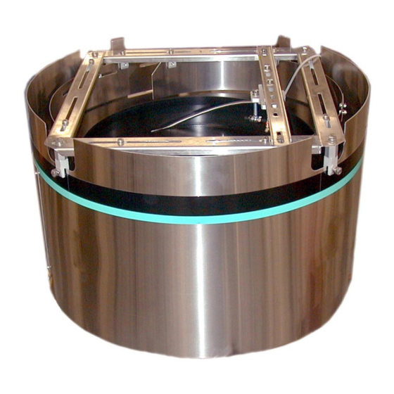
The FR-20 & FR-30 Centrifugal Feeders unscramble, feed and orient product. Simply put, it delivers aligned product. Except for obtainable rates and the size of product, the FR-20 and FR-30 function identically. Generally, the FR-30 is used to handle larger product or achieve higher output rates. -
Page 8: Figure 1-2. Fr-20 Feeder Specifications
FR-20 & FR-30 Feeder Installation/Maintenance FR-20 Feeder Specifications Product Specifications: ANSI Metric A. Outer Wall Diameter 27.25" 693mm 24.25" ± 1" 615mm ±25mm B. Overall Height C. Discharge Height 17.5" 445mm D. Bowl Outside Diameter 24.81" 631mm E. Rim Width 2.32"... - Page 9 Chapter 1 Feeder Description & Specifications FR-30 Feeder Specifications Product Specifications: ANSI Metric A. Outer Wall Diameter 40.50" 1029mm 26.25" ± 1" 667mm ±25mm B. Overall Height C. Discharge Height 18.5" 470mm D. Bowl Outside Diameter 36.13" 918mm E. Rim Width 3.63"...
-
Page 10: Safety Precautions
Install Safety Covers! Make sure the feeder remains safe to operate. Be sure all safety covers have all been installed before returning the feeder to normal operation. Safety covers on the FR-20 and FR-30 feeders include any covers installed by your direct supplier, as well as the exit area cover (which protects the operator from moving sprockets and belts.) - Page 11 FR-20 & FR-30 Feeder Installation/Maintenance DonÕ t Adjust Air Jet Flow Controls. It’s okay to adjust the main air regulator to its correct setting for your installation. However, air jets and their individual flow controls have all been carefully preset to work with your product;...
-
Page 12: Installation & Startup
Installation & Startup Unpacking & Inspection Step 1Ñ I nspect & Unpack the Crate. Remove packing materials from sensors, tooling and moving parts. Make a visual check to be sure parts have not come loose during shipping. If you find any concealed damage, call the shipping carrier and your direct sup- plier immediately. - Page 13 FR-20 & FR-30 Feeder Installation/Maintenance If you are supplying your own prefeeder, you are responsible for: Providing and installing the feeder's bowl level switch so it can control the product flow of your prefeeder. Setting the timing delay for the feeder's bowl level switch.
-
Page 14: Figure 3-1. Measuring & Changing Bowl Speed
Chapter 3 Installation & Startup How to Set Proper Bowl Speed Ask your direct supplier for the actual linear feet per minute at which the bowl should rotate. For reliability, set the bowl to match that speed. To set bowl speed, you will need a hand-held tachometer (analog or digital) with a surface speed wheel indicator (see Figure 5-1). - Page 15 FR-20 & FR-30 Feeder Installation/Maintenance Running Product For The First Time Step 1Ñ V erify Changeover Setup. If your feeder is tooled to run multiple product, ensure the feeder is set up for the product you want to run. Inspect the exit of the feeder. If Step 2Ñ...
-
Page 16: Figure 3-2. Dc Ansi Wiring Diagram
Chapter 3 Installation & Startup FR-20/30 DC ANSI-Suggested Wiring Diagram * Replaceable Spare: π See Pages 37-40. Plug-In Horsepower Resistor (R21) Rotation: Brown White Field ∏ Armature Black Line Input Green ∂ Shunt Wound INH2 DC Motor INH1 ∑ DC Motor... - Page 17 FR-20 & FR-30 Feeder Installation/Maintenance FR-20/30 AC Metric - Suggested Wiring Diagram FRAME LOW VOLTAGE HIGH VOLTAGE 220V - 50 HZ 380V - 50 HZ SCHALT. SCHALT. SINGLE SPEED Specifications Model Inventory Number: FR20XXXASM FR30XXXASM Drive Motor: Drive Motor: Motors .18 hp Motor, 220/380...
- Page 18 Chapter 3 Installation & Startup FR-20/30 AC ANSI - Suggested Wiring Diagram Note: Reverse rotation by interchanging any two line leads: " " " " " " & & & & & & & Specifications Model Inventory Number: FR20XXXASA FR30XXXASA...
-
Page 19: Preventive Maintenance
Lubrication Bearings On all FR-20 and FR-30 models, grease nipples for lubrication are located on the outside of the upper and lower spindle bearings. Use any lithium grease conforming to NLGI Grade 2 consistency; the grease should be free of dust, particles and abrasives. -
Page 20: Repair & Troubleshooting
Repair & Troubleshooting Adjusting Bowl Runout Bowl runout needs to be set if the bowl is removed. Adjust runout with power off and drive chain disengaged. For runout specifica- tions, see Chapter 1. Disconnect power and air. Remove the Step 1Ñ G ain Access. cover from the exit area of the feeder. -
Page 21: Torque Limiter: Replacement/Adjustment
For best results, use identical replacement parts. Replacement parts by serial number are listed for the metric FR-20 in Chapter 6, Spare Parts. Retrofitting a torque limiter onto a unit that has none is not required. - Page 22 Chapter 5 Repair & Troubleshooting Torque Limiter, Adjusting Nut Assembled Lockwasher To lock the adjusting nut in place, one lockwasher tab up is bent up (not shown) Disk Spring against the adjusting nut. Avoid completely flattening the disk Pressure Plate spring, or the friction facings may tear away if there is a parts jam.
- Page 23 Bowl Drive Spindle Sprocket ............20 Teeth Bowl Drive Torque Limiter Sprocket ........... 28 Teeth Chain Lengths FR-20 - Bowl Drive Chain (51 Links) ......#40 x 25.5" Long FR-30 - Bowl Drive Chain (57 Links) ......#40 x 28.5" Long...
-
Page 24: Adjusting Chain Tension
Adjusting Backup Ring Clearance A number of design improvements were made to all models (cold rolled and stainless steel, ANSI and metric) of the FR-20 and FR-30 that affect the backup ring clearance adjustment of the units listed below. - Page 25 OLDER STYLE If it becomes necessary to adjust the backup ring clearance of an Backup Ring Clearance FR-20 or FR-30 feeder that contains an older style tooling frame, Adjustment Procedure you must change the backup ring clearance by raising or lowering the entire bowl and spindle shaft assembly.
- Page 26 To change the clearance between the backup ring and top rim of the bowl on Figure 5-4. older style FR-20 and FR-30 feeders, loosen the threaded clamp collar on the OLDER STYLE lower spindle bearing. Next, turn the threaded spindle shaft while holding the lower spindle bearing's threaded clamp collar stationary.
- Page 27 If it becomes necessary to adjust the backup ring clearance of an Backup Ring Clearance FR-20 or FR-30 feeder which contains a current style tooling frame you can change the backup ring clearance by raising the square tooling frame at the four adjustment points around the top of the feeder.
-
Page 28: Removing Bowl For Machining
Mounting hardware is provided with the replacement bowl. Note machining Outer allowed) that unlike the FR-30, all versions of the FR-20 are supplied with a Edge solid case urethane bowl that can be machined if needed. Do not machine the FR-30 standard injection foam urethane bowl,... - Page 29 FR-20 & FR-30 Feeder Installation/Maintenance Is the feeder’s bowl speed set incorrectly? Is there a changeover procedure you have overlooked? Is the feeder’s main air regulator set incorrectly? Step 2Ñ I nspect Your Product. After checking the feeder, check to...
- Page 30 . r e . t c o l f , f f . r o . t r . t r . t r . r e . c s i t r Figure 5-7. FR-20 & FR-30 Feeder Troubleshooting...
- Page 31 ' . i t c . t l . t l t Õ l l o b i l l l o s ' . i t c Figure 5-8. FR-20 & FR-30 Feeder Troubleshooting, Continued...
-
Page 32: Spare Parts
Spare Parts Notice to Shibuya Hoppmann Customers: To ensure receiving the right spare part, consult your system operations manual. Refer to the feeder's model and serial number, which was recorded, on the front of this manual when ordering replacement or service parts for your prefeeder. This information is necessary when ordering replacement parts or service. - Page 33 FR-20 & FR-30 Feeder Installation/Maintenance FR-20 Critical Replacement Parts - ANSI (DC & AC Motors) t i r e l l FR-20 Recommended Replacement Parts - ANSI (DC & AC Motors) n i l " 5 o l l —...
- Page 34 Chapter 6 Spare Parts FR-30 Critical Replacement Parts - ANSI (DC & AC Motors) t i r e l l FR-30 Recommended Replacement Parts - ANSI (DC & AC Motors) n i l " 5 o l l — a l i —...
- Page 35 FR-20 & FR-30 Feeder Installation/Maintenance FR-20 & 30 Critical Replacement Parts - Metric (AC Motors) t i r FR-20 & 30 Recommended Replacement Parts - Metric (AC Motors) n i l " 5 o l l — a l i —...
Need help?
Do you have a question about the FR-20 and is the answer not in the manual?
Questions and answers