Advertisement
Quick Links
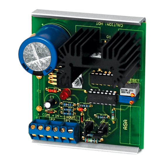
ANALOG SIGNAL AMPLIFIER
SERIES
Installation & Operation Instructions
GENERAL INFORMATION
The ASA is an analog signal ampli er which
accepts an analog (voltage or current) signal and
outputs a voltage signal. Several preset input
ranges are jumper selectable. It is designed to give
a Building Automation System signal output the
power (wattage) to control Maxitrol™ Gas Valves
normally installed in rooftop units. The top-adjust
trimmer potentiometers can be used to make ne
adjustments of gain and o set. The output gain
can be adjusted anywhere from 1 to 20 times the
input on the ASA (gain will vary depending on
type of input). By using voltage divider
applications, the ASA can also accept a resistance
input. The o set of the output can be +/- 0 to 20
VDC. If above 30 watts, derate load current and
calculate again (P out = [(V out/Load) (V out)]
and/or (P out = (Load Current)(V out)). The ASA is
eld calibratable, however, factory calibration is
available upon request for an additional charge.
This will speed up installation time for the end
user.
MOUNTING INSTRUCTIONS
Circuit board may be mounted in any position. If
circuit board slides out of snap track, a
non-conductive "stop" may be required. Use only ngers to remove board from snap track. Slide out of
snap track or push against side of snap track and lift that side of the circuit board to remove. Do not ex
board or use tools.
WIRING INSTRUCTIONS
PRECAUTIONS
• Remove power before wiring. Never connect or disconnect wiring with power applied.
•
When using a shielded cable, ground the shield only at the controller end. Grounding both
ends can cause a ground loop.
• It is recommended you use an isolated UL-listed class 2 transformer when powering the unit
with 24 VAC. Failure to wire the devices with the correct polarity when sharing transformers may
result in damage to any device powered by the shared transformer.
• If the 24 VDC or 24VAC power is shared with devices that have coils such as relays, solenoids, or
other inductors, each coil must have an MOV, DC/AC Transorb, Transient Voltage Suppressor (ACI
Part: 142583), or diode placed across the coil or inductor. The cathode, or banded side of the DC
Transorb or diode, connects to the positive side of the power supply. Without these snubbers,
coils produce very large voltage spikes when de-energizing that can cause malfunction or
destruction of electronic circuits.
• All wiring must comply with all local and National Electric Codes.
Automation Components, Inc.
2305 Pleasant View Road | Middleton, WI 53562
Phone: 1-888-967-5224 | Website: workaci.com
FIGURE 1: DIMENSIONS
2.90" (73.78mm)
3.25"
(82.55mm)
3.25"
(82.55mm)
2.70" (68.58mm)
Page 1
Phone: 1-888-967-5224
Website: workaci.com
0.70"
(17.78mm)
Version: 6.0
I0000602
Advertisement

Related Manuals for aci ASA Series

Summary of Contents for aci ASA Series
- Page 1 • If the 24 VDC or 24VAC power is shared with devices that have coils such as relays, solenoids, or other inductors, each coil must have an MOV, DC/AC Transorb, Transient Voltage Suppressor (ACI Part: 142583), or diode placed across the coil or inductor. The cathode, or banded side of the DC Transorb or diode, connects to the positive side of the power supply.
- Page 2 FIGURE 2: WIRING Voltage Current Signal Signal Input Input Negative No O set Positive O set O set 24 VAC/VDC Power Supply Analog Input Signal Analog Output Signal (up to 2 Amps, or 30 watts power) FACTORY CALIBRATION The ASA is set as follows: Voltage Input Signal No O set to the Output Signal Input to Output Signal Gain (1:1)
- Page 3 J2 - OFFSET: Set in the ‘O’ position for no o set to the output. If you will require a (+) or (-) o set, you will set this shunt in the appropriate position in Step 6 Step 3) Wiring Connections Make the following connections with the power OFF : Connect a 24 to 30 VDC or VAC power supply (see power supply information on speci cations or detail at bottom of page 3 instructions ) to the ASA terminals (+) and COM.
- Page 4 -40 to 150°F (-28.9 to 65.5°C) WARRANTY The ASA Series is covered by ACI’s Two (2) Year Limited Warranty, which is located in the front of ACI’S SENSORS & TRANSMITTERS CATALOG or can be found on ACI’s website: www.workaci.com. W.E.E.E. DIRECTIVE At the end of their useful life the packaging and product should be disposed of via a suitable recycling centre.