
Summary of Contents for ACD CAL 2000
- Page 1 Advanced Calibration Designs, Inc. CAL 2000 Calibration Gas Generator Instruction Manual...
-
Page 2: Table Of Contents
Instruction Manual Cal 2000 Calibration Gas Instrument TABLE OF CONTENTS General Description Page 2 Normal Operation: Diffusion Mode Page 7 III. Normal Operation: Sample Draw Mode Page 12 Menu Options Page 14 Maintenance Page 16 Troubleshooting Page 17 VII. Standard Warranty Page 19 VIII. - Page 3 WARNING: This instrument generates calibration gas for toxic gas detectors. The instruction manual should be read and understood prior to operation of the instrument. Failure to operate the instrument correctly can lead to improper calibrations. This instrument conforms to the protection requirements of the EC DIRECTIVE 89/336/EEC on Electromagnetic Compatibility (EMC), in accordance with the provisions of Statutory Instrument 2372.
-
Page 4: General Description
Each cell has a built-in memory chip that tells the Cal 2000 instrument what type and range of gas can be generated and how much cell life is remaining. - Page 5 Cell Installation and Removal There are no tools required by the end user for service of the instrument. The electrochemical cells are shipped seperate of the unit and should be installed on receipt. To install the cell, remove the bottom cover of the instrument.
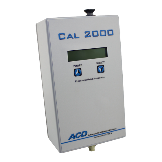
- Page 6 Digital Display The Cal 2000 has a liquid crystal display (LCD) located on the front of the instrument. This display is protected by a thin, clear plastic cover that is part of the front label and may be replaced if it becomes scratched or unclear.
- Page 7 Mass Flow Sensor The Cal 2000 has a built-in mass flow sensor that measures the flow rate of the instrument. This information is used in two ways. With the pump engaged, it is used to control the pump to the desired flow rate over a range of 0.2 to 1.0 LPM. With the pump disabled, it is used to measure the air flow rate drawn through the Cal 2000 by an external pump. This information is used to adjust the cell current to the desired ppm. The flow meter should be calibrated against a primary mass flow standard every 12 to 24 months. Internal Charcoal Filter An internal charcoal filter is provided to scrub contaminated air and provide a clean baseline for “zeroing” sensors. This filter should be replaced on a yearly basis and is removed by pulling out the grey plunger at the top of the unit. Spare filter elements can be purchased through...
- Page 8 Optional items available for the Cal 2000 include: AC Adapter The Cal 2000 may also be operated from an AC adapter. The AC adapter converts the AC voltage supplied from the main power lines to 6 VDC which is used in lieu of the batteries. The adapter plugs into the instrument from the underside of the case directly into the power board and is independent of polarity. If needed, contact the factory for exact specifications of the...
-
Page 9: Normal Operation: Diffusion Mode
NORMAL OPERATION: DIFFUSION MODE To start the generator, press and hold the POWER switch, located in the middle left front of the instrument, until the display reads A. C. D., approximately three (3) seconds. Release the switch immediately thereafter. The instrument will sequence through several screens as follows: A. - Page 10 The Calibration Date refers to when the instrument itself was last calibrated at the Factory. It does not refer to the calibration date of the generating cells, which are field replaceable. The following status screens indicate the remaining cell life and battery status. Cell Life 049 Hrs 59 Mns Battery Status 100% remaining...
- Page 11 000 ppm, the instrument will not generate any gas, although it will continue to pump. The minimum and maximum ppm settings are dependent upon the flow rate and the type of generating cell installed in the instrument. The Cal 2000 will read the memory chip inside the generating cell and automatically display the minimum and maximum ppm available for the flow rate that the instrument is set to.
- Page 12 1.0 to 10.0 PPM and 10 to 50 PPM. When the end of a given range is reached, pressing the appropriate up or down arrow will automatically toggle the display to the next appropriate range. Note that to obtain higher concentrations of gas simply reduce the flow rate of the instrument.
- Page 13 At any time you may reset either the flow rate or the ppm rate by pressing the SELECT button and entering the status screens as described above. When you are finished generating gas and wish to turn off the instrument, press and hold the POWER switch until the purge screen is displayed. Purging ... Standby: 300 sec The instrument will purge itself of gas for 300 seconds and then automatically shut off. At any time during this period, you may turn the instrument back on by pressing the SELECT switch and entering the status screens as described above. You must change either the flow rate or the ppm setting and then the instrument will immediately go to the stabilization screen and...
-
Page 14: Normal Operation: Sample Draw Mode
III. NORMAL OPERATION: SAMPLE DRAW MODE The instrument may also be operated in a sample draw mode where the internal pump is disabled and the air is drawn through the instrument by an external pump. This mode is used for calibrating sample draw instruments. To enter the sample draw mode, press the SELECT switch when the flow status screen is displayed. - Page 15 WARNING: Do not adjust the flow rate to more than 0.0 LPM while the Cal 2000 is attached to a sample draw unit or damage may occur to the instrument. Also, do not attach the Cal 2000 to pumps drawing more than 5 LPM.
-
Page 16: Menu Options
Foreign Language Option The menu options can be adjusted to read in German, French, or Spanish. To change the language, start the unit as you normally would. When the ACD screen appears, A. C. D. VI Copyright 2000 press the SELECT button. This will bring up the following screen:... - Page 17 It is important to note that when you enter the Quick Select mode for the H2S cell, you cannot change the flow rate of the instrument. The Cal 2000 instrument will automatically vary the flow rate to achieve the different ppm concentrations of H2S.
-
Page 18: Maintenance
It is recommended that the electrolyte solution be replaced on an annual basis for most gases generated by the CAL 2000. The exception to this is the ClO2 electrolyte. Please refer to the instructions enclosed with every chlorine dioxide cell or replacement electrolyte pack. -
Page 19: Troubleshooting
VI. TROUBLESHOOTING No Power To Instrument There are two common causes for the unit to not power up when the POWER switch is pressed for three seconds. The most common is that the batteries are dead. Try replacing the batteries with new alkaline batteries or try powering the unit from the AC power adapter. - Page 20 “Cell Failure!” accompanied by an audible beep. There are two possible causes for a cell failure. One cause is that the instrument has not detected a cell. The other is that a high voltage has been detected across the cell. If the cell is not initially detected by the processor, the unit will display cell failure and immediately shut down (without entering ‘purge mode’).
-
Page 21: Standard Warranty
The following is a listing of the available electrochemical Cal 2000 cells and their standard prorated warranty when installed in equipment manufactured and supplied by Advanced Calibration Designs, Inc. - Page 22 50 Hour Generating Cells 1. Chlorine - One year or 50 hours of use. 2. Hydrogen Sulfide - One year or 50 hours of use. 3. Hydrogen Cyanide - One year or 50 hours of use . 4. Hydrogen - One year or 50 hours of use . 5. Chlorine Dioxide - One year, 50 hours of use . 100 Hour Generating Cells 1.
-
Page 23: Accessory Items / Parts List
VIII. ACCESSORY ITEMS / PARTS LIST The following items are available as accessories for the Cal 2000: Description 113-0402-00 Male Hose Barb Quick Connector, 1/8” OD hose 150-0121-00 Charcoal Filter Element, one each 150-0131-00 Charcoal Filter Element, package of 12 180-0100-00 Empty Plastic Bottle with Pipette for Electrolyte 193-0100-00 Electrolyte, Chlorine (50 ml bottle) 193-0101-01 Electrolyte, Chlorine Dioxide (1 Qty. Refill) 193-0101-05 Electrolyte, Chlorine Dioxide (5 Qty. Refill) - Page 24 510-2060-00 Chlorine Dioxide Cell, 50 hrs 510-2060-20 Chlorine Dioxide Cell, 100 hrs 510-2070-00 Hydrogen Cyanide Cell, 50 hrs 510-2090-00 Hydrogen Cell, 50 hrs 510-2090-20 Hydrogen Cell, 100 hrs 715-0403-0X 3 Foot Hose w/connector, low flow, 1/4” OD 715-0405-0X 5 Foot Hose w/connector, low flow, 1/4” OD 730-0615-00 Hard-body, Water Resistant, Padded Carrying Case 910-0603-00 Instruction Manual Page 22...
-
Page 25: Instrument Specifications
European Standards approval for Zone 0 Manufactured by: dvanced alibration esigns, Inc. 2024 W. McMillan Street Tucson, Arizona 85705 USA Phone: 520 290 2855 - Fax: 520 290 2860 Int’l Phone: 001 520 290 2855 - Fax: 001 520 290 2860 email: ACD@goacd.com website: www.GoACD.com Page 23... - Page 26 Advanced Calibration Designs, Inc. 2024 W. McMillan St. Tucson, Arizona 85705 USA Telephone: (520) 290-2855 Fax: (520) 290-2860 Toll Free: (800) 737-0223 Email: acd@goACD.com Web: www.goACD.com P/N 910-0603-00...
Need help?
Do you have a question about the CAL 2000 and is the answer not in the manual?
Questions and answers