Advertisement
Quick Links
Advertisement

Related Manuals for WarmlyYours Riviera


Summary of Contents for WarmlyYours Riviera
- Page 1 Installation & Operation Manual for WarmlyYours Towel Warmers...
-
Page 2: Safety Information
Thank you for choosing your fi nely crafted WarmlyYours Towel Warmer. Now you can add luxury and comfort to your bathroom with the soothing embrace of a warm towel or bathrobe upon stepping from the shower. The radiant heat from the Towel Warmer warms your towel. - Page 3 Affi xing the Towel Warmer to the Wall Step 1 Draw a diagram of the preferred location of the brackets and the electrical connection on the Towel Warmer box to create a template (see Step 2 for template instructions). At least two of the four brackets must be attached directly to a stud.
- Page 4 This example shows 16” on center construction. Your situation may vary depending on your stud spacing. WARNING: Locations of electrical box and anchor points may vary. Measure all dimensions prior to rough-in and installation. Riviera stud stud 16” (406mm) ” (550mm)
- Page 5 Affi xing the Towel Warmer to the Wall - cont’ d Note: Dimensions shown are distances between the center of anchor points. This example shows 1 6 ” on center construction. Your situation may vary depending on your stud spacing. WARNING: Locations of electrical box and anchor points may vary.
- Page 6 Affi xing the Towel Warmer to the Wall - cont’ d Note: Dimensions shown are distances between the center of anchor points. This example shows 1 6 ” on center construction. Your situation may vary depending on your stud spacing. WARNING: Locations of electrical box and anchor points may vary.
- Page 7 Affi xing the Towel Warmer to the Wall - cont’ d S t ep 4 Attach all four brackets to their desired positions on the Towel Warmer. See pgs. 7-1 0 for bracket assembly instructions specifi c to the model you selected. S t ep 5 Lay the template on a fl...
- Page 8 Bracket Assembly D i agrams - Portofi no d e f...
- Page 9 Bracket Assembly Instructions - Portofi no Step 1 Measure for position of brackets using the template if desired. At least two brackets must attach to a stud. Step 2 Affi x part C to the wall using screw e and drywall anchor d* where necessary.* * Slot in C should face downwards.
- Page 10 Bracket Assembly Diagrams - Riviera & Catalina...
- Page 11 Bracket Assembly I n s tru c tio n s - Riviera & Catalina S t ep 1 Measure for position of brackets using the template if desired. At least two brackets must attach to a stud. S t ep 2 Affi...
- Page 12 Diagram A. Diagram B. Label O-ring Diagram Step 9 With the brackets now in place, slide electrical wires through rubber O-ring on electrical plate. Refer to Diagram A. Do not remove rubber o-ring from electrical plate under any circumstances. Step 10 Adjust the Towel Warmer to desired position from wall and screw the screws into place, but do not tighten at this time.
- Page 13 Final Installation Instructions (for all models) - cont’ d Step 11 Have a certifi ed professional wire the Towel Warmer to the electrical line according to code, referring to the detailed wiring diagram provided in Appendix B. Step 12 Push the wires into the electrical box and screw the cover plate to the outside of the box.
-
Page 14: Operation
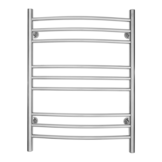
Timer can be set to operate in manual mode to function as a simple ON-OFF switch. Your WarmlyYours Towel Warmer is designed to gradually warm towels over the course of a day and works best when towels are left to hang for at least 3 hours. - Page 15 Product Construction - Towel Warmer The Towel Warmer is constructed from High Carbon Steel, using tubing with a wall thickness of between 0.8 mm and 1 . 2 mm. The steel tubing is brazed together with full, continuous joints. The fi nished assembly is either electroplated or powder coated, depending on the model and style.
- Page 16 WarmlyYours.com Inc. for this product, the National Electric Code (NEC), and all applicable local building and electrical codes. Controls sold under the WarmlyYours.com Inc. name are warranted for one year from the date of sale. Any suspected defect must be reported by registered letter immediately upon discovery.
- Page 17 Appendix A1: Rough-In Diagram - Riviera Note: Dimensions shown are distances between the center of anchor points. This example shows 16” on center construction. Your situation may vary depending on your stud spacing. WARNING: Locations of electrical box and anchor points may vary.
- Page 18 Appendix A2: Rough-In Diagram - Catalina Note: Dimensions shown are distances between the center of anchor points. This example shows 16” on center construction. Your situation may vary depending on your stud spacing. WARNING: Locations of electrical box and anchor points may vary. Measure all dimensions prior to rough-in and installation.
- Page 19 Appendix B: Wiring Diagram (All models) 2” x 4” ELECTRICAL 120 Volt TIMER BOX FOR TIMER LINE (black) 120 a.c. HOT NEUTRAL NEUTRAL (white) LOAD GROUND (blue) BLACK GREEN GROUND TOWEL WARMER WHITE LOAD (black or red) NEUTRAL LOAD (white) GROUND (green/yellow) 2”...
Need help?
Do you have a question about the Riviera and is the answer not in the manual?
Questions and answers